IDEX wrong extruder motor turning
-
Hi guys.
So I rebuilt a BCN3D Sigma R16 from scratch. I got it for free because it was stripped for replacement parts. Basically just the linear rails and the Z-axis assembly were left.
I mostly got it working with the U-axis and all, however there is one problem I can't understand yet.
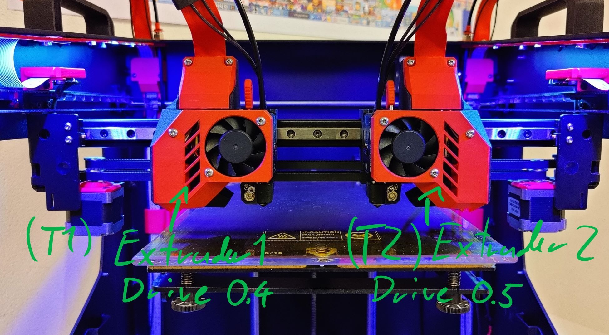
If I switch to T1 (left extruder) everything works fine if i give an extrude command (G1 E10 F300). However if I switch to T2 (right extruder) and give the same command, the left extruder motor from T1 turns and not the right one from T2.
T1 is mapped to drive 4 and T2 to 5.
Its not that the drive is faulty.
If i plug and map the X-axis on drive5, I can move it without problems.
It's not an extruder motor problem because it works fine if I plug it in drive 4.
Next I tried the mixing stuff aka M567 with E0:1. Doesn't work.
Also just (G1 E0:10 F300) gives the array too long error.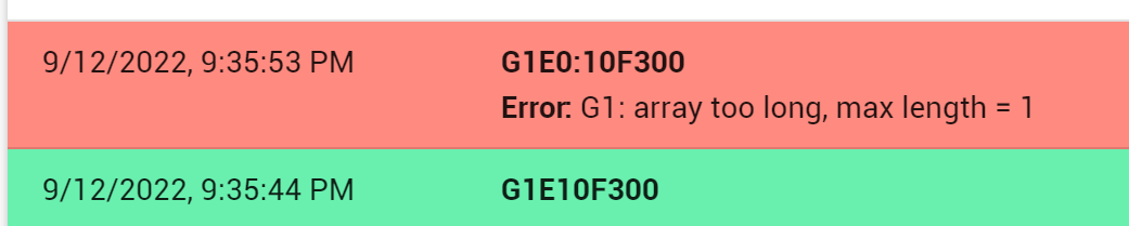
So I don't know if I messed up in the config or misunderstood the IDEX guide .
If someone has an idea on how to get extruder 2 turning please let me know")
Thanks in advance.Here are the relevant parts of the config file. Heater, Fans and tempsensors on T2 work just fine.
; Configuration file for Duet 3 MB 6HC (firmware version 3.3) ; executed by the firmware on start-up ; ... ; Drives M569 P0.0 S1 ; physical drive 0.1 goes forwards M569 P0.1 S0 ; physical drive 0.2 goes backwards M569 P0.2 S0 ; physical drive 0.3 goes backwards M569 P0.3 S0 ; physical drive 0.4 goes backwards M569 P0.4 S0 ; physical drive 0.5 goes backwards M569 P0.5 S0 ; physical drive 0.6 goes backwards M584 X0.2 Y0.1 Z0.0 U0.3 E0.4:0.5 ; set drive mapping M350 X16 Y16 Z16 U16 E16:16 I1 ; configure microstepping with interpolation M92 X80 Y80 Z1600 U80 E400:400 ; set steps per mm M203 X10000 Y10000 Z1000 U10000 E5000:5000 ; set maximum speeds (mm/min) M566 X750 Y750 Z60 U750 E900:900 ; set maximum instantaneous speed changes (mm/min) M201 X1000 Y1000 Z200 U500 E1200:1200 ; set accelerations (mm/s^2) M906 X750 Y1400 Z1100 U750 E650:650 I30 ; set motor currents (mA) and motor idle factor in per cent M84 S60 ; Set idle timeout ; Axis Limits M208 X-20 Y0 Z0 U0 S1 ; set axis minima M208 X205 Y295 Z200 U225 S0 ; set axis maxima ... ; Heaters M308 S0 P"temp0" Y"thermistor" T100000 B4138 ; configure sensor 0 as thermistor on pin temp0 M950 H0 C"out0" T0 ; create bed heater output on out0 and map it to sensor 0 M307 H0 B0 R0.364 C334.5 D2.24 S1.00 ; disable bang-bang mode for the bed heater and set PWM limit M140 H0 ; map heated bed to heater 0 M143 H0 S120 ; set temperature limit for heater 0 to 120C M308 S1 P"temp1" Y"pt1000" ; configure sensor 1 as PT1000 on pin temp1 M950 H1 C"out1" T1 ; create nozzle heater output on out1 and map it to sensor 1 M307 H1 B0 R2.683 C270.1 D6.12 S1.00 ; disable bang-bang mode for heater and set PWM limit M143 H1 S450 ; set temperature limit for heater 1 to 450C M308 S2 P"temp2" Y"pt1000" ; configure sensor 2 as PT1000 on pin temp2 M950 H2 C"out2" T2 ; create nozzle heater output on out2 and map it to sensor 2 M307 H2 B0 R2.799 C266.8 D5.32 S1.00 ; disable bang-bang mode for heater and set PWM limit M143 H2 S450 ; set temperature limit for heater 2 to 450C ; Fans M950 F0 C"out3" Q65535 ; create fan 0 on pin out3 and set its frequency M106 P0 C"Extruder Fan 1" S0 H1 T50 ; set fan 0 name and value. Thermostatic control is turned on M950 F1 C"out5" Q65535 ; create fan 1 on pin out5 and set its frequency M106 P1 C"Part Fan 1" S0 H-1 ; set fan 1 name and value. Thermostatic control is turned off M950 F2 C"out4" Q65535 ; create fan 2 on pin out4 and set its frequency M106 P2 C"Extruder Fan 2" S0 H2 T50 ; set fan 2 name and value. Thermostatic control is turned on M950 F3 C"out6" Q65535 ; create fan 3 on pin out6 and set its frequency M106 P3 C"Part Fan 2" S0 H-1 ; set fan 3 name and value. Thermostatic control is turned off ; Tool 1 M563 P1 S"Exruder 1" D0.4 H1 F0:1 ; define tool 1 G10 P1 X0 Y0 Z0 ; set tool 1 axis offsets G10 P1 R0 S0 ; set initial tool 1 active and standby temperatures to 0C ; Tool 2 M563 P2 S"Extruder 2" D0.5 X3 H2 F0:3 ; define tool 2 on U-axis G10 P2 U0 Y0 Z0 ; set tool 2 axis offsets G10 P2 R0 S0 ; set initial tool 2 active and standby temperatures to 0C ; Custom settings are not defined -
@pxp11 it's your M563 tool mapping causing the issue.
M563 P1 S"Exruder 1" D0.4 H1 F0:1The D parameter is the extruder number so should be D0 or D1, not D0.4 and D0.5
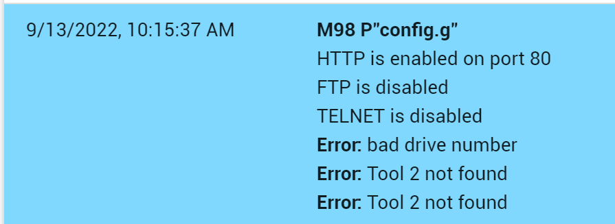
If you send M98 P"config.g" through console it may show you that error in config.
Also, when extruding with multiple tools you only send one E number and that gets applied to the active tool. If you want to extrude both (e.g. for copy mode), create a third tool mapped to both extruders
-
@pxp11 To elaborate on what @engikeneer has said, when you use M584, the first "E" drive becomes D0, the second D1, the third D2 etc. These are the drive numbers you should use in your tool definitions, not the actual driver designation. You are not the first to fall foul of that "gotcha", nor will you be the last.
-
Thanks a lot. @deckingman @engikeneer
So it's a little embarrassing but I actually tried that before but it didn't work. Because for me T1 H1 and D1 belong together as do T2 H2 D2... see where I'm going with this. If you aren't accustomed to start index counting from 0 things like this happen
 ...
...
But yes with T1 D0 and T2 D1 everything works just fine.
-
@pxp11 Welcome to my world! I don't have an IDEX but I've been using multi-input hot ends for years (my current one has 6 inputs) and still make mistakes when assigning extruders to tools or when changing mixing ratios.
-
 undefined PXP11 marked this topic as a question
-
undefined PXP11 has marked this topic as solved