5 bar scara on duet3!
-
Hello!
After a bit of a hiatus, I've got something to show off again! I tried my belt-box idea, and that was terrible. There was a ton of backlash as the belts wound up with tension. Instead I decided to make a new gear box with a finer toothed gear (module 1 rather than 2) and a 30:1 ratio to get a ton of precision and torque. I also switched to nema 17 motors which is working great! So now I can move the nema 23's to the Z axis.
I need to get some pillow blocks in for the 20mm rod, but this worked really well just spinning in the static rod mounts I had. I was having a hard time connecting to the tube clamps, so instead I found some 20mm shaft collars that were 32mm for their OD's. This created a static point to mount to the 20mm solid rod which is much easier to mount a gear to.
One thing I could use help with is some sort of rotational dampener. I've got my acceleration and jerk settings down pretty low for 100-150mm/s print moves which is ok (accelerations to 250mm/s^2 and jerk to 2mm/s^3). I'm hoping the pillow blocks I'm getting will just be a bit sticky to introduce some friction to reduce wobble around corners. Ultimately this will be running 1mm nozzles and up, so I don't expect super fast print speeds anyway, but the stiffer I can make the system the better print quality I'll get out of it.
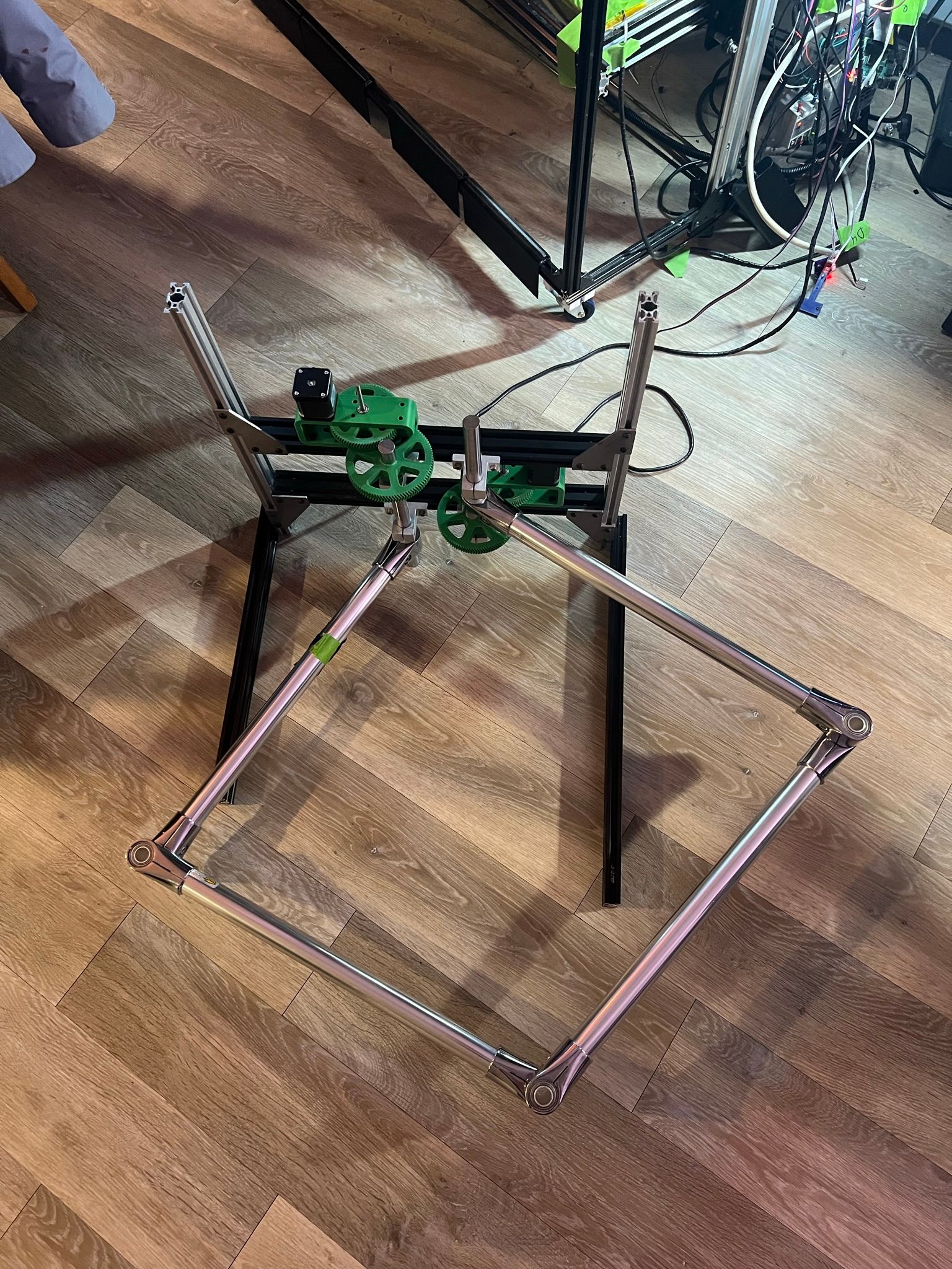
Possible upgrades are to come up with a stiffer design for the gear box housing as I can see it flexes a bit as the gears load up. I'll probably move the idler compound gear to an 8mm shaft rather than a 5mm shaft at some point too.
From here, I think I'm ready to start getting the 80/20 framing sorted so it can be mounted to the Z axis which I need to start putting together and sorting out as well!
-
@michaelr123 said in 5 bar scara on duet3!:
come up with a stiffer design for the gear box housing
nice to hear that you make progress.
For stiffness, bending depends on e-module of materials, which is about 1 to 3 GPa for plastics, 70 for aluminium and steel 210. So connecting two points of the axes with an aluminium construction would be better than plastic housing.
You could use your two horizontal aluminium extrusions and assemble the two steppers upside and the other one downside, so the two big wheels are not in eachs way and use the aluminium extrusion to hold the axes in place.
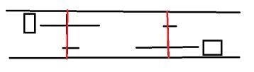
The red lines are the axes connected to the extrusions. M569's direction must be reversed than by changing the S parameter.
To connect aluminiun - holder - ball bearing - shaft I used a SHF16 or other depending on the shaft diameter. SHF is similar like your SH holders, but other orientation (or fixed shaft and wheel on ball bearing, the wheels connected). Anyway, the shaft should be fixed in place at two points. Tilting the shafts or hindering it will be critical for all XYZ positions, because the arms leverage small tiltings. The longer the arms, the more. (I use flanged ball bearings like F688 to hinder it so slip through).
When the axes are stable and the hinges don't have play, I think you'll not need a dampered rotating axis anymore. You could additionally lower acceleration values to have lower vibrations, if acceleration is the cause.
-
@michaelr123 if you ask me for another recommendation (
") ) , e.g. optimal gear ratio for the wheels, I would say calculate the extrusion rate you can get with the 1mm nozzle and calculate back how the maximum speed of the arms can be. Then choose as much high ratio as possible, maybe 1:50 or even 1:100, because you'll get higher precision.
) , e.g. optimal gear ratio for the wheels, I would say calculate the extrusion rate you can get with the 1mm nozzle and calculate back how the maximum speed of the arms can be. Then choose as much high ratio as possible, maybe 1:50 or even 1:100, because you'll get higher precision. -
@michaelr123 another idea if you 3d print your wheels anyway. A construction like this one:
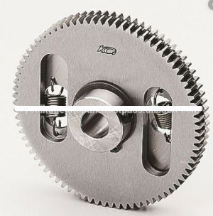
two wheels, the springs make sure the one is pressing against the teeth at one flank/(edge) and the other wheel against the other, so no backlash. (but the newest RRF has backlash correction, this may be no problem anymore)
-
I agree on mounting the bearings to the aluminum extrusion rather than into a printed part. I'll move to that style of construction on the next redesign.
I'll use an 8mm SHF bearings for the idle compound gear and then figure out how to mount the motor directly to the extrusion. Ideally I could even put a bearing on the other end of the shaft to eliminate the cantilever for the drive gear.
We'll see what I can do with the gear ratio. I'm not sure I want to go much smaller than 16t on the small gears, though 12t gears would get me to a 53.333 ratio and 14t gears would take me to 39.18... I'll think more on that, but I need to be careful how much larger the gears get as I need room behind the assembly to run the Z-axis equipment which is what I'm working on today! more pictures to come!
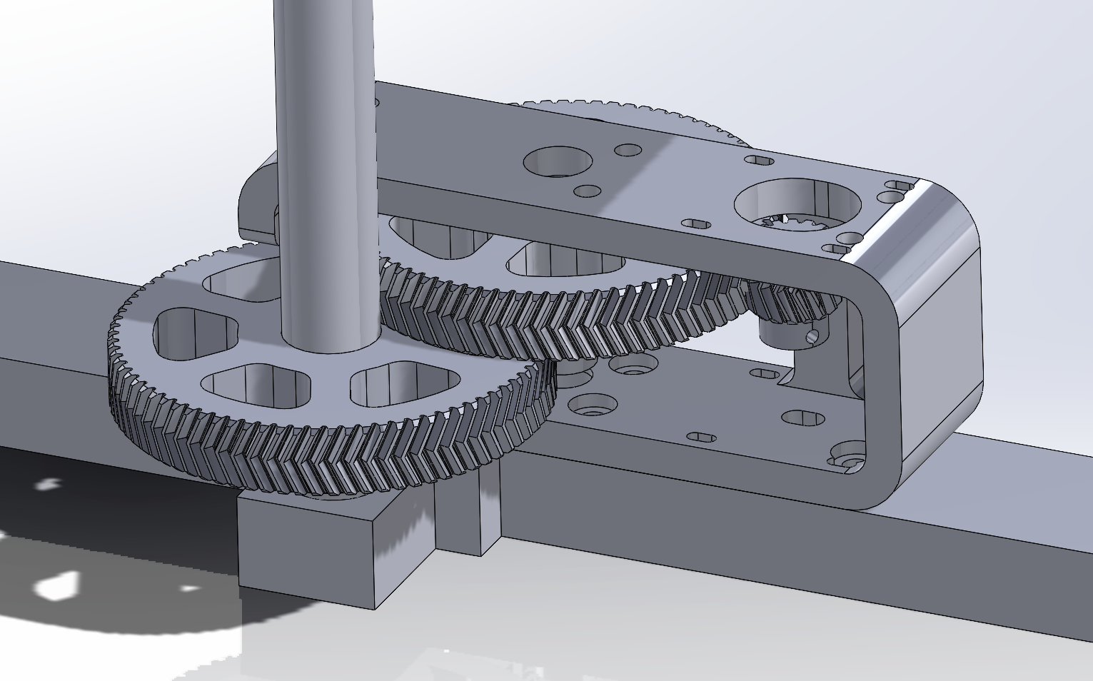
So far the double helical gears are getting me what I perceive as zero backlash, we'll see how those wear in. I know I want to stick with one idler shaft as having 2 in the last setup was flimsy and difficult to manage belt tensions across.
-
@michaelr123 said in 5 bar scara on duet3!:
So far the double helical gears are getting me what I perceive as zero backlash, we'll see how those wear in
Didn't know these "herringbone gears" were special regarding backlash? They are known to have low torque ripple and don't put sideload on the gear...
If you have finalized gear design, try to get them in PA-like resin. I guarantee, it's a hole new level of accuracy, like FDM printing with a 0.04mm nozzle and 0.05mm layer height.
And this PA-like stuff has nylon-equivalent characteristics.

-
I guess technically any gear can become "zero backlash" if you drive them together a bit by shortening the center-center distance between the gears. I thought helical gears had some benefits for backlash due to the constant contact, but engineering school was a long time ago and I'm not certain on that.
Ideally I would buy machined plastic gears or get a strain wave / cycloidal gear box up and running:
https://www.youtube.com/watch?v=-wFO_AbnbZQ&ab_channel=ZeroBacklashUltimately it comes down to the artifacts in the prints, but so far the 30:1 compound gears seem pretty good just from jogging the system around. These gears are all printed from polymaker ABS, but the final rendition will be PA6-CF if I decide to stick with a compound gear box.
As for resin printing, I haven't gotten into it so I can't comment on that, though the resolution from those machines is super impressive. What brand of resin do you recommend?
Thanks for the input!
-
Anybody know if Koal design is on this forum at all?
https://www.youtube.com/@koaldesigns
His machine was a big inspiration for me and it looks like he got some good results with his strain-wave reducer design before moving on to a different project. I've got a bunch of 5mm bearings laying around now that I could repurpose for something like this!
-Michael
-
@michaelr123 there was some discussion around July 2022 and 2020 here https://forum.duet3d.com/topic/17421/robotic-kinematics
harmonic drive vs cycloidal drive. -
@michaelr123 this is my current list about harmonic drive on thingiverse, my comments are in german, sorry. I've developed one my own, but didn't publish it. I want to do it when I'm satisfied with the result. I've marked myself the good ones (in my opinion) green, they are the ones from bartdring, Andy, Trollox, ReDesign, Dexter/Baxter, m2rechtin, Cameron.
vermutlich gute sind grün markiert
sortiert nach Jahr (und thingiverse Nummer)jdow, 2012, innen 2 Kugellager
- https://www.thingiverse.com/thing:20177
- YT 3D printed Harmonic Drive
emmett, 2014, innen 2-er planetary, nur Minimalteile
- https://www.thingiverse.com/thing:219779
- YT Preassembled Harmonic Drive
Alphie, 2014, innen 2, mit großem Kugellager (ähnlich cross roller)
- https://www.thingiverse.com/thing:391538
- YT 3D printed Harmonic Drive
mtourne, 2016
- https://www.thingiverse.com/thing:1622691
- stl, Solidworks
- letzte Version auf https://github.com/mtourne/mecha/tree/master/Harmonic drive
bartdring, 2016, innen 10 Kugellager
- https://www.thingiverse.com/thing:1966551
- stl things
- 1:39
- YT 3D Printed Harmonic Drive
Andy, 2016, innen 2 Kugellager
- https://hackaday.io/project/18388-mammoth-arm
○ If the payload too heavy , slipping is happening. This is the first version, next version I will trying to move the heavy motor back. But that will introduce new transmission system, like timing belt.
Simon Merrett, 2017, innen 2 Kugellager, FlexSp mit belt
- https://www.thingiverse.com/thing:2013137
- https://hackaday.io/project/19405-strain-wave-gear-with-timing-belts
- https://hackaday.com/2017/01/17/3d-printed-strain-wave-gear-needs-your-help/
- Updated model, 2018, YT Strain Wave and Hypocycloidal 3D Printed Gears Update
DevonHsin, 2017, innen 2, FlexSpline HTD-3 belt
- https://www.thingiverse.com/thing:2086118
- stl thingstodo auswerten:
https://www.thingiverse.com/thing:2107873
https://www.thingiverse.com/thing:2129630
https://www.thingiverse.com/thing:2255991
https://www.thingiverse.com/thing:2626728
https://www.thingiverse.com/thing:2282268Trollox, 2017, für Nema 23, innen viele Kugeln
- https://www.thingiverse.com/thing:2735297
- stl, step, easm, pdf Dateien
ReDesign, 2018, innen 12 Kugellager
- YT 3D printed harmonic drive with servo motor
- YT 3D Printed - Harmonic Drive
- bisher keine anderen Quellen zu finden (Doku, src)
Brian Benchoff, 2018
- https://hackaday.com/2018/06/19/printing-strain-wave-gears/
Johannes Hassler, 2018, innen 2
- Version 4: https://hackaday.io/project/120377-3d-printed-strain-wave-gear
- https://github.com/HasslerEngineering/3D-Printed-Strain-Wave-Gear/
Dexter, Baxter, Haddington Dynamics, 2018
- https://hackaday.com/2018/11/15/an-in-depth-look-at-dexter-the-robotic-arm/
- Encoder: https://github.com/HaddingtonDynamics/Dexter/wiki/Encoders
Levi Janssen, 2019, innen 2
- YT Making a 3D Printed Harmonic Drive Using a Timing Belt
ymtlab (YT: YMT Lab), 2019/2020, innen 6 Kugellager
- https://www.thingiverse.com/thing:4505585
- YT 3D Printed Strain Wave Gear
- YT 3D printed harmonic drive (Ring type test)
- 1:39
m2rechtin, 2020, innen 2, 2 Versionen rund und eckig
- https://www.thingiverse.com/thing:4686542
- stl
- YT DIY 3D Printed Harmonic Drive (Strain Wave Gearing)
Cameron, 2020
- https://hackaday.io/project/174195-embedded-strain-wave-actuator
- hohe Payload 3 kg für 6 DOF robot
Arcannys, 2021, FlexSpline mit belt
- https://www.thingiverse.com/thing:4915441
- kein Video
3DprintedLife (YT Name), 2021, innen 2 Kugellager
- https://hackaday.com/2021/05/24/a-high-torque-3d-printed-harmonic-drive/ (Autor Danie Conradie)
- hp/source: https://github.com/DDeGonge/OS-ARM/tree/main/cad/HarmonicDrive75mm
- https://discord.com/channels/747166166459351121/747180569984761937
- YT My 3D Printed Harmonic Drive Performs Surprisingly Well! -
@michaelr123 said in 5 bar scara on duet3!:
What brand of resin do you recommend?
I just started exploring resin printers in december 22, so not much to recommend. I chose 'Sunlu' ABS-like because I'm happy with their filament.
-
Thanks for the resource!
I finally figured out how to find 3mm-GT2 closed loop belts on Amazon, lol. Have you seen any difference between HTD and GT2 belt profile for this application? This could be getting too nit-picky... but more importantly you can get 12-15mm wide belt in 3mm pitch! My issue was that I couldn't find wider 2mm GT2 to make one of these belted harmonic drives. I live the idea of a gear or a belt reduction into the harmonic drive as well. This quickly gets you to a gear ratio over 100:1.
My ultimate plan now is to wrap the harmonic driver around the 20mm rod I'm using, and then have a belted connection to a motor off to the side. Super clean and compact, but more CAD and prototyping... lol
-
@michaelr123 the HTD, GT2, T2.5 etc belts have different tooth and valley (is this the correct name??) profiles, so this will be important. GT2 has less play than the other profiles, because they are half-circle, and the others trapezoidal.
When the belts are used curved, the counterpart must be changed to match the teeth, this is to be considered. I tried to use a GT2-belt-to-GT2-belt assembly on a wheel, but this didn't work, because after a few mm the teeth didn't match anymore. But if you 3D print the counterpart, you can design it matching.
-
@JoergS5 I've followed design of the 3D printed harmonic drives for a while, but the crucial part was always the flex belt.
Now I've started studying silicone moulding with resin-printed moulds. Could it be interesting for harmonic drives, too?
The belts could be "mass-produced" from rubber-like silicone. Also silicone moulds can be used for production of 2k-epoxy resin parts, like pulleys or involute gears.
It's all made possible because of the superfine resolution of resin prints. -
@o_lampe said in 5 bar scara on duet3!:
studying silicone moulding with resin-printed moulds
BG, we are true brothers in mind
That's the reason why I had a short thread in the forum asking how many times it's possible to recycle ABS (or 3D printing material in general): I plan 3D printing molds and make injection molding of such things like the flex spline.
The first mold 3D printed, then inject something easy to fill in (PLA eg), then make a silicone mold of this, then injection mold something strong like aluminium or flexible like PP, maybe mixing with polycarbonate.
There are aluminium sorts which can be similar flexible as string steel.But I plan to make a postprocess CNC routing, because I expect that the teeth will not be perfect.
-
haha I was driving home from work contemplating if you could mass produce a plastic, lower cost harmonic drive for all the mechatronics nerds out there
I feel like there's a need out there for a lowish cost, zero backlash reducer for robotics projects.Interesting to hear about the belt flex. Does that present as backlash or just lack of holding torque? Can you just increase the squish rate a bit to make up for that flexibility?
I keep going back to this guy as he's got a simple design and has demonstrated a large format scara arm printing really well. https://www.youtube.com/watch?v=2WuPUq7ELWI&ab_channel=KoalDesigns
I'm thinking about modifying this design a bit to use an HTD belt rather than an SLS printed belt and to also wrap this design around a 20mm rod which is what I'm using in my design. The integration with the belt reducer to the input of the harmonic drive is slick too. Once you realize that the stationary spline is just a modified pitch circle with a few teeth less than than the drive side it's pretty simple to design. The HTD tooth profile is simpler than GT2 as well.
I'm planning for a 9mm belt and some 3mm bearings that are 4mm wide stacked two tall mounted on 3mm shaft rather than screws. The height of this assembly should drive holding torque, which I don't want or need as I'd rather have the arms snap out of the way if they bump into anyone or anything
I'm hoping I can cut out the 90mm outside bearings and just have everything ride on the 20mm rod down the center as I have plenty of 20mm bearings and that's going to be way more rigid than bearings mounted into plastic. more to come on this design!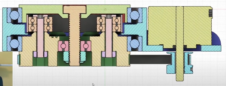
-
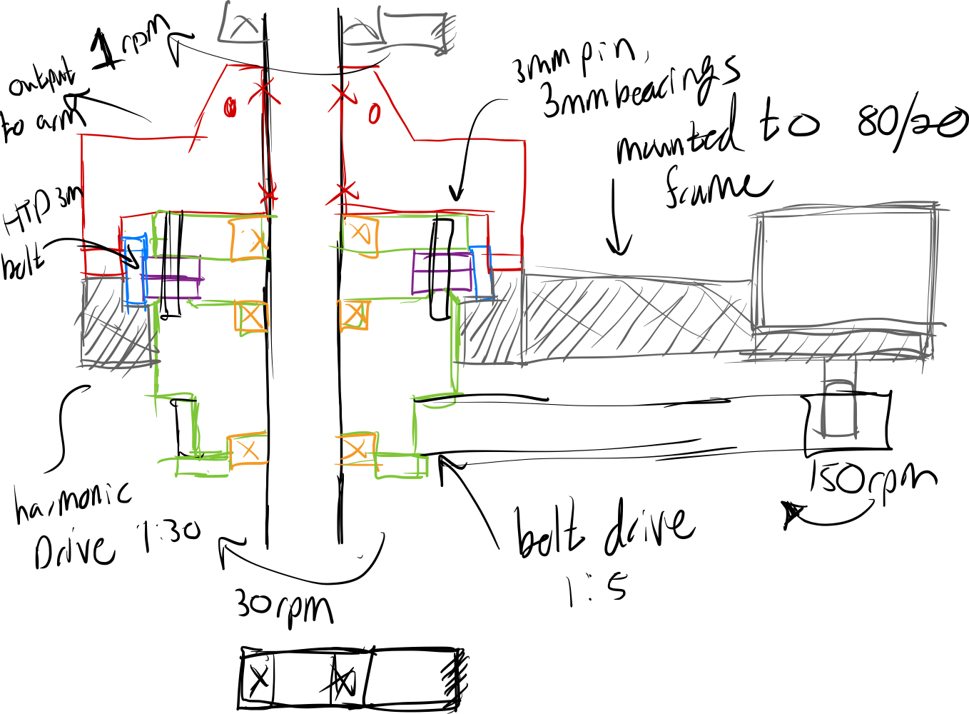
Here's a quick sketch I came up with for a design to try. I think I can use pairs of bearings to accomplish the same thing as as one big bearing on the outside. The 20mm rod in black down the center is the out put, and the red part from the harmonic drive is fixed to it. The green part is the input to the reducer and sits on bearings on the 20mm rod. The gray part is the fixed part of the reducer and is mounted to the 80/20 frame. I'll have to see how well I can float this part around the reducer. I suppose that's the potential hold up, but it's worth a go.
-
@michaelr123 a topic which you should imho add to the list to develop is an encoder for the actuators to detect skipped steps or alike. If you don't want to add it now, you should add space to your planning to have space to add it later.
-
I would love to add encoders to this and my duet powered voron at some point! I'm just waiting for the software and hardware to develop to the point where it's more or less a drop in upgrade with a bit of tuning. So far it seems like the project is in development stage and has just started to get dedicated hardware built for the duet 3 ecosystem like from LDO. Unfortunately I don’t have the time to dig into code and helping develop the project otherwise I would! I will probably gear the encoder directly to the 20mm shaft to make sure I’m getting right to the actual output rather than going through the harmonic drive. You’re getting the control theory side of my brain going again haha
To start off I’m going to get the dedicated drive unit for the extruder to cutdown the number of cables to just a power and signal cable. Managing a giant bundle of cables on my old machine was always a pain.
I’ll report back on the harmonic drive idea, but it’ll come down to how well it actually works on on the printer. The more I look the more I see a war going on between cycloidal drives and harmonic drives. I think it’s pretty well understood that fully printed flex spline cups don’t hold up well over time so you have to use some sort of flexible timing belt to perform this task.
Cycloidal boxes just use a pile of hardware, especially if you want multiple stages to smooth out the motion. I’ve seen what look to be robust solutions using both styles of gear boxes, so hopefully I can just pick one and make it work.
-
@michaelr123 said in 5 bar scara on duet3!:
fully printed flex spline cups don’t hold up well over time
I've bought used harmonic drives and even those flexsplines made out of steel have very damaged teeth, so I don't use them as templates.
Edit Feb 19: I thought about it: the teeth are very damaged, but I don't know how the harmonic drive was used. It depends on torque usage etc., so I don't have information about how long it can be used without replace. 3D printers will probably have low torque and robots with low payload also.