Duet3D Logo Duet3D
    • Tags
    • Documentation
    • Order
    • Register
    • Login

    Milling motor control - Duet3/PWM Converter

    Scheduled Pinned Locked Moved Solved
    CNC
    3
    25
    1.2k
    Loading More Posts
    • Oldest to Newest
    • Newest to Oldest
    • Most Votes
    Reply
    • Reply as topic
    Log in to reply
    This topic has been deleted. Only users with topic management privileges can see it.
    • dc42undefined
      dc42 administrators @Nightowl
      last edited by dc42

      @Nightowl yes that's the correct one.

      You appear to be using the 5V_PWM (aka Laser/VFD) output from the Duet to drive the PWM to voltage converter. In that case you should connect the PWM+ input of the converter to the out9 pin of that connector, and the PWM- input of the converter to the GND pin. This is because the out9 output on that connector is active high. The +5V pin is intended for powering small servos when they are attached to that connector.

      Duet WiFi hardware designer and firmware engineer
      Please do not ask me for Duet support via PM or email, use the forum
      http://www.escher3d.com, https://miscsolutions.wordpress.com

      1 Reply Last reply Reply Quote 0
      • Nightowlundefined
        Nightowl
        last edited by

        This is a bit surprising. It seems the minimum speed of the milling motor is 4,000rpm and it will run at that speed when powered up, irrespective of whether the digital interface is used or not.

        This might present me with a problem, but I think there's a way around it - but I might need help.

        Presently, for the Makita palm router, I use the following code to configure it in the config.g file:

        ; Makita and relay configuration
        M950 R0 C"out1+out7" L0:18000	; enable router relay on out7
        M563 P0 S"Makita" R0		; assign spindle 0 to tool 0 and name it Makita
        T0				; select tool 0
        

        ...which works well. It essentially turns the Makita on via this Keene relay.

        I had planned to use the following code for the Sorotec:

        ; Spindle configuration
        M950 R0 C"vfd" L0:25000 Q1000	; create spindle with index 0
        M563 P0 S"Sorotec" R0		; create tool 0 with spindle 0 and name it "Sorotec"
        T0				; select tool 0
        

        ...but I think I will have to do one of two things.

        Firstly, keep the code as it is and assign different tool numbers, but I'm not sure if/how I could activate (essentially) two tools at the same time.

        Secondly, combine the code into one configuration 'group', but I'm not sure there is any benefit in this, over the first option.

        Has anyone got any ideas, please?

        Thanks

        Few things are more dangerous than taking the advice of someone who thinks he knows what he's doing.
        I'm still on my learning curve, so take everything I say with caution!

        RatRig 1075, Duet3 MB6HC, Sorotec SFM 1000 PV-ER milling motor, Hobbyist

        jay_s_ukundefined 2 Replies Last reply Reply Quote 0
        • jay_s_ukundefined
          jay_s_uk @Nightowl
          last edited by

          @Nightowl could you not add an extra relay to control the power and then add another output on the M950? like you have your mikita

          Owns various duet boards and is the main wiki maintainer for the Teamgloomy LPC/STM32 port of RRF. Assume I'm running whatever the latest beta/stable build is

          Nightowlundefined 1 Reply Last reply Reply Quote 0
          • Nightowlundefined
            Nightowl @jay_s_uk
            last edited by

            @jay_s_uk

            That's what I was thinking. As I see it, any M3 command would need to 'operate' the relay (as it currently does for the Makita) and the Snnnn part to control the speed.

            I'm just not sure how to incorporate the code to make that happen.

            Few things are more dangerous than taking the advice of someone who thinks he knows what he's doing.
            I'm still on my learning curve, so take everything I say with caution!

            RatRig 1075, Duet3 MB6HC, Sorotec SFM 1000 PV-ER milling motor, Hobbyist

            dc42undefined 1 Reply Last reply Reply Quote 0
            • jay_s_ukundefined
              jay_s_uk @Nightowl
              last edited by

              @Nightowl said in Milling motor control - Duet3/PWM Converter:

              ; Spindle configuration
              M950 R0 C"vfd" L0:25000 Q1000 ; create spindle with index 0
              M563 P0 S"Sorotec" R0 ; create tool 0 with spindle 0 and name it "Sorotec"
              T0

              add another output to the M950, i.e.
              M950 R0 C"vfd+out1" L0:25000 Q1000 ; create spindle with index 0
              and wire the relay to out1 (you can adjust that as well).
              M3 should activate that relay and M5 should turn it off.

              Owns various duet boards and is the main wiki maintainer for the Teamgloomy LPC/STM32 port of RRF. Assume I'm running whatever the latest beta/stable build is

              Nightowlundefined 1 Reply Last reply Reply Quote 0
              • dc42undefined
                dc42 administrators @Nightowl
                last edited by

                @Nightowl see the section on configuring spindles at https://docs.duet3d.com/en/User_manual/Reference/Gcodes#m950-create-heater-fan-spindle-or-gpioservo-pin for an explanation of the suggestion by @jay_s_uk.

                Duet WiFi hardware designer and firmware engineer
                Please do not ask me for Duet support via PM or email, use the forum
                http://www.escher3d.com, https://miscsolutions.wordpress.com

                Nightowlundefined 1 Reply Last reply Reply Quote 0
                • Nightowlundefined
                  Nightowl @jay_s_uk
                  last edited by Nightowl

                  I see! Thank you, @jay_s_uk
                  Of course, that makes sense. It's the same idea as for the Makita (apart from the pins) so if I used this, to configure the motor:

                  ; Spindle configuration
                  M950 R0 C"vfd+out7" L0:25000 Q1000	; create spindle with index 0
                  M563 P0 S"Sorotec" R0			; create tool 0 with spindle 0 and name it "Sorotec"
                  T0					; select tool 0
                  

                  ...that would get me to where I want to be, whilst keeping the relay on the existing pins.

                  That's brilliant, thank you so much!

                  Few things are more dangerous than taking the advice of someone who thinks he knows what he's doing.
                  I'm still on my learning curve, so take everything I say with caution!

                  RatRig 1075, Duet3 MB6HC, Sorotec SFM 1000 PV-ER milling motor, Hobbyist

                  1 Reply Last reply Reply Quote 0
                  • Nightowlundefined
                    Nightowl @dc42
                    last edited by

                    Thanks, @dc42, I'll check it out 👍

                    Few things are more dangerous than taking the advice of someone who thinks he knows what he's doing.
                    I'm still on my learning curve, so take everything I say with caution!

                    RatRig 1075, Duet3 MB6HC, Sorotec SFM 1000 PV-ER milling motor, Hobbyist

                    1 Reply Last reply Reply Quote 0
                    • Nightowlundefined
                      Nightowl
                      last edited by

                      Just out of curiosity, how do I find out what the Q setting should be?

                      Is this information relative to the PWM controller, which is advertised as being 1kHz to 3kHz?

                      Thanks

                      Few things are more dangerous than taking the advice of someone who thinks he knows what he's doing.
                      I'm still on my learning curve, so take everything I say with caution!

                      RatRig 1075, Duet3 MB6HC, Sorotec SFM 1000 PV-ER milling motor, Hobbyist

                      jay_s_ukundefined dc42undefined 2 Replies Last reply Reply Quote 0
                      • jay_s_ukundefined
                        jay_s_uk @Nightowl
                        last edited by

                        @Nightowl its more relative to VFD

                        Owns various duet boards and is the main wiki maintainer for the Teamgloomy LPC/STM32 port of RRF. Assume I'm running whatever the latest beta/stable build is

                        1 Reply Last reply Reply Quote 0
                        • dc42undefined
                          dc42 administrators @Nightowl
                          last edited by

                          @Nightowl said in Milling motor control - Duet3/PWM Converter:

                          Just out of curiosity, how do I find out what the Q setting should be?
                          Is this information relative to the PWM controller, which is advertised as being 1kHz to 3kHz?

                          Yes, use between 1000 and 3000.

                          Duet WiFi hardware designer and firmware engineer
                          Please do not ask me for Duet support via PM or email, use the forum
                          http://www.escher3d.com, https://miscsolutions.wordpress.com

                          1 Reply Last reply Reply Quote 1
                          • Nightowlundefined
                            Nightowl
                            last edited by

                            Some progress!

                            Using the code below, I can now start/stop the motor with M3 Sn and M5 respectively, but I can't change the speed: it is constant at 4,000RPM, which suggests to me that the voltage required to change the speed isn't there. Possibly a fault with the PWM converter?

                            Here's the code:

                            ; Milling motor and relay configuration
                            M950 R0 C"vfd+out7" L0:25000 Q1000	; enable router relay on out7
                            M563 P0 S"Sorotec" R0 			; assign spindle 0 to tool 0 and name it Sorotec
                            T0					; select tool 0
                            M5					; ensure motor is turned off
                            

                            Few things are more dangerous than taking the advice of someone who thinks he knows what he's doing.
                            I'm still on my learning curve, so take everything I say with caution!

                            RatRig 1075, Duet3 MB6HC, Sorotec SFM 1000 PV-ER milling motor, Hobbyist

                            jay_s_ukundefined 1 Reply Last reply Reply Quote 0
                            • jay_s_ukundefined
                              jay_s_uk @Nightowl
                              last edited by

                              @Nightowl have you adjusted the variable resistor on the top? have you set the VFD up for PWM control? I had to change some of the registers on my VFD to use PWM rather than RS485

                              Owns various duet boards and is the main wiki maintainer for the Teamgloomy LPC/STM32 port of RRF. Assume I'm running whatever the latest beta/stable build is

                              Nightowlundefined 1 Reply Last reply Reply Quote 0
                              • Nightowlundefined
                                Nightowl @jay_s_uk
                                last edited by

                                @jay_s_uk

                                If you mean this one (arrowed), no I haven't:

                                Screenshot 2022-12-02 at 10.22.48.png

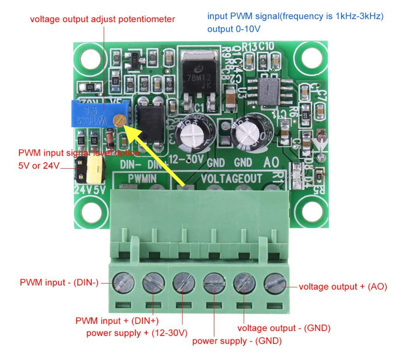
                                I'm not using a VFD, though. Just following the instructions from the Ooznest website, the M950 guide and this document.

                                I've just noticed point 2 indicates the "5V/24V PWM input signal level option" should be set to 5V, so I'll need to check that...

                                Few things are more dangerous than taking the advice of someone who thinks he knows what he's doing.
                                I'm still on my learning curve, so take everything I say with caution!

                                RatRig 1075, Duet3 MB6HC, Sorotec SFM 1000 PV-ER milling motor, Hobbyist

                                1 Reply Last reply Reply Quote 1
                                • Nightowlundefined
                                  Nightowl
                                  last edited by Nightowl

                                  One thing I've checked - very carefully, is the voltage across the 12V and GND connectors, adjacent to the 5V PWM connectors, on the Duet control board, and they're only providing 6V.

                                  Also, the voltage across terminals GND and AO on the PWM board doesn't change when I adjust the motor speed (without the cable connected to the motor, so there's no load) from M3 S1000 to M3 S25000

                                  That can't be right, surely?

                                  Also, the jumper on the PWM board is set to 5V.

                                  Few things are more dangerous than taking the advice of someone who thinks he knows what he's doing.
                                  I'm still on my learning curve, so take everything I say with caution!

                                  RatRig 1075, Duet3 MB6HC, Sorotec SFM 1000 PV-ER milling motor, Hobbyist

                                  jay_s_ukundefined 1 Reply Last reply Reply Quote 0
                                  • jay_s_ukundefined
                                    jay_s_uk @Nightowl
                                    last edited by

                                    @Nightowl can you just confirm where the PWM is wired to on the duet board?

                                    Owns various duet boards and is the main wiki maintainer for the Teamgloomy LPC/STM32 port of RRF. Assume I'm running whatever the latest beta/stable build is

                                    Nightowlundefined 1 Reply Last reply Reply Quote 0
                                    • Nightowlundefined
                                      Nightowl @jay_s_uk
                                      last edited by Nightowl

                                      @jay_s_uk

                                      Certainly. The pins on the PWM board are connected to the Out9 VFD\Laser\Servo Drive header:

                                      Port 1 (PWM in -ve) to 5V_Ext
                                      Port 2 (PWM in +ve) to Out9
                                      Port 3 (Power Supply 12-30V) to 12V
                                      Port 4 (Power Supply GND) to GND
                                      Port 5 (Voltage Out GND) to GND
                                      Port 6 (Voltage Out +ve AO) to the motor plug

                                      There is a loop between Ports 4 and 5, and this is also connected to the GND wire on the motor plug.

                                      The third wire from the motor plug is connected to the PSU 24V +ve of the PSU.

                                      Few things are more dangerous than taking the advice of someone who thinks he knows what he's doing.
                                      I'm still on my learning curve, so take everything I say with caution!

                                      RatRig 1075, Duet3 MB6HC, Sorotec SFM 1000 PV-ER milling motor, Hobbyist

                                      jay_s_ukundefined 1 Reply Last reply Reply Quote 0
                                      • jay_s_ukundefined
                                        jay_s_uk @Nightowl
                                        last edited by

                                        @Nightowl thats where you'll be going wrong then as the header you're using is always on (i think). change numbers 3 and 4. it'll also probably explain why its always on at power up without that relay. i would just wire them to an out connector and switch your M950 accordingly.

                                        Owns various duet boards and is the main wiki maintainer for the Teamgloomy LPC/STM32 port of RRF. Assume I'm running whatever the latest beta/stable build is

                                        Nightowlundefined 1 Reply Last reply Reply Quote 0
                                        • Nightowlundefined
                                          Nightowl @jay_s_uk
                                          last edited by

                                          @jay_s_uk
                                          Forgive me, but aren't they 'just' the power supply to the converter? The switch operating the relay (to stop it the motor spinning) is on out7.

                                          Also @dc42 posted earlier (I missed it, sorry) that I should connect PWM in -ve to GND (not 5V-Ext)

                                          Few things are more dangerous than taking the advice of someone who thinks he knows what he's doing.
                                          I'm still on my learning curve, so take everything I say with caution!

                                          RatRig 1075, Duet3 MB6HC, Sorotec SFM 1000 PV-ER milling motor, Hobbyist

                                          jay_s_ukundefined 1 Reply Last reply Reply Quote 1
                                          • jay_s_ukundefined
                                            jay_s_uk @Nightowl
                                            last edited by

                                            @Nightowl ah bugger, you're right. i looked at the diagram wrong

                                            Owns various duet boards and is the main wiki maintainer for the Teamgloomy LPC/STM32 port of RRF. Assume I'm running whatever the latest beta/stable build is

                                            1 Reply Last reply Reply Quote 0
                                            • First post
                                              Last post
                                            Unless otherwise noted, all forum content is licensed under CC-BY-SA