Z Offset calculation and Height Map inconsistent
-
Good morning, I make another post about the height map because I'm starting to think that maybe could be a problem with the latest RRF releases....Now I've installed the 3.4.5 and other than the height map problems I've started to have a "z offset" problem...Here's the problems:
-
I follow this procedure https://docs.duet3d.com/en/User_manual/Connecting_hardware/Z_probe_testing to calibrate my Z offset (the probe I use is a VINDA) particullary what described in the chapter "Calibrate the Z probe trigger height", As written I repeat the steps from 5 to 8 three or four times ALWAYS getting a result of 1.12 - 1.114 mm. When I start a print the Z offset is ALWAYS 0.2mm LOWER than the needed and the first layer is so squashed that the filament doesn't extrude until I raise by 0.2-0.25mm the nozzle using the babystepping. If I set the G31 in the config.g file with Z0.99 the print start about at the correct height but the following problem will occur:
-
As I wrote in my previous post I know my bed plate is awful but for now I don't have the money to buy a new one. I've corrected the settings for my probing points as told me and I've made a compensation map. During the print I see the Z axis moving to compensate but the result is awful, I've always the front side of the bed ALMOST correctly compensated but the back side is squashed from left to right
The mesh compensation is a problem I've been facing since a month or two (honestly I don't know since what RRF version) but the Z offset problem has appered with the 3.4.5.
Any suggestion? At now I think that the problems could be the VINDA or the RRF for the first problem but the second remains a mistery....The VINDA is mounted in front of the Nozzle and for that reason even if I have a Y max dimension of 310mm I reduce it at 280mm to be sure to print in a "probed/compensated" area.
I attach my config.g, my start gcode and my height map:
cacl310; Configuration file for Duet WiFi (firmware version 3)
; executed by the firmware on start-up
;
; generated by RepRapFirmware Configuration Tool v3.1.4 on Sun Nov 01 2020 08:34:36 GMT+0100 (Ora standard dell’Europa centrale)

; General preferences
G90                                                    ; send absolute coordinates...
M83                                                    ; ...but relative extruder moves
M550 P"DragonCore"                                     ; set printer name
M669 K1                                                ; select CoreXY mode

; Network
M552 S1                                                ; enable network
M586 P0 S1                                             ; enable HTTP
M586 P1 S1                                             ; enable FTP
M586 P2 S1                                             ; enable Telnet

; Drives
M569 P0 S1                                             ; physical drive 0 goes backwards
M569 P1 S1                                             ; physical drive 1 goes backwards
M569 P2 S0                                             ; physical drive 2 goes backwards
M569 P3 S0                                             ; physical drive 3 goes backwards
M569 P4 S0                                             ; physical drive 4 goes backwards
M584 X0 Y1 Z2 E3                                       ; set drive mapping
M350 E16 I0                                        ; configure microstepping without interpolation
M350 X16 Y16 Z16 I1                                    ; configure microstepping with interpolation
M92 X79.8 Y79.8 Z2376.48 E415                    ; set steps per mm
M566 X1200.00 Y1200.00 Z12.00 E6000                 ; set maximum instantaneous speed changes (mm/min) ####################################
M203 X18000.00 Y18000.00 Z360.00 E5000.00      ; set maximum speeds (mm/min) ############################
M201 X9000.00 Y9000.00 Z100.00 E5000.00           ; set accelerations (mm/s^2) ###############################
M906 X1200 Y1200 Z900 E500 I30                       ; set motor currents (mA) and motor idle factor in per cent ###################################e
M84 S30                                                ; Set idle timeout

; Axis Limits
M208 X0 Y-25 Z0 S1                                       ; set axis minima ################################
M208 X313 Y320 Z350 S0                                 ; set axis maxima #########################################

; Endstops
M574 X1 S1 P"xstop"                                    ; configure active-high endstop for low end on X via pin xstop
M574 Y1 S1 P"ystop"                                    ; configure active-high endstop for low end on Y via pin ystop
M574 Z1 S2                                             ; configure Z-probe endstop for low end on Z

; Z-Probe
M558 P9 C"^zprobe.in" H5 F300 T6000                    ; set Z probe type to bltouch and the dive height + speeds
G31 P500 X-26.116 Y-29.279 Z0.99                           ; set Z probe trigger value, offset and trigger height  ###############################################
;M557 X5:285 Y0:290 S15                                ; define mesh grid #####################################################
M557 X10:285 Y10:290 S15                                ; define mesh grid #####################################################

; Heaters
M308 S0 P"bedtemp" Y"thermistor" T100000 B4092         					; configure sensor 0 as thermistor on pin bedtemp
M950 H0 C"bedheat" T0                                  					; create bed heater output on bedheat and map it to sensor 0
M307 H0 B0 S1.00                                       					; disable bang-bang mode for the bed heater and set PWM limit
M140 H0                                                					; map heated bed to heater 0
M143 H0 S120                                           					; set temperature limit for heater 0 to 120C
M308 S1 P"e0temp" Y"thermistor" T100000 B4725 C7.060000e-8
M950 H1 C"e0heat" T1                                   					; create nozzle heater output on e0heat and map it to sensor 1
M307 H1 B0 S1.00                                       					; disable bang-bang mode for heater  and set PWM limit
M143 H1 S285                                           					; set temperature limit for heater 1 to 280C

; Fans
M950 F0 C"fan0" Q2000                                   ; create fan 0 on pin fan0 and set its frequency
M106 P0 S0 H-1                                         ; set fan 0 value. Thermostatic control is turned off
M950 F1 C"fan1" Q500                                   ; create fan 1 on pin fan1 and set its frequency
M106 P1 S1 H1 T50                                      ; set fan 1 value. Thermostatic control is turned on
M308 S4 Y"mcu-temp" A"MCU"                             ; configure sensor 3 as thermistor on pin e1temp for left stepper
M308 S3 Y"drivers" A"Drivers"  						   ; configure sensor 4 as temperature warning and overheat flags on the TMC2660 on Duet

; =============================================
; = LED FAN                                   =
; =============================================
M950 F11 C"exp.heater4"
M106 P11 S0

; Tools
M563 P0 S"Master" D0 H1 F0                             ; define tool 0
G10 P0 X0 Y0 Z0                                        ; set tool 0 axis offsets
G10 P0 R0 S0                                           ;  set initial tool 0 active and standby temperatures to 0C

; Miscellaneous
M575 P1 S1 B57600                                      ; enable support for PanelDue
M912 P0 S-2.45                                         ; calibrates CPU temp
M501                                                   ; load saved parameters from non-volatile memory

; =========================================================
; =               D R A G O N    C O R E                  =
; =========================================================

; ==================
; = VARIABLES      =
; ==================
global primingExtruderAmount=12

; ==================
; = NOZZLES WIPING =
; ==================
global XWipeEnterCoord=0
global YWipeEnterCoord=0
global XWipeStartCoord=38
;global XWipeEndCoord=77
global XWipeEndCoord=45
global XWipeFinalCoord=147
global YWipeFinalCoord=-25

; ==================
; = FOR PA SETTINGS=
; ==================
;global g_pa_setting       = 0.12        	 ; the current pressure advance setting
;global g_pa_increment      = 0.02        ; the amount to increment the pressure advance setting
;global g_pa_layer_count    = 20         ; For 0.2mm layer height the number of layers to count to cause the incrementing of the pressure advance setting
;global g_pa_layer_count    = 10         ; For 0.6mm layer height the number of layers to count to cause the incrementing of the pressure advance setting
;global g_pa_layer_count    = 30         ; For 0.1mm layer height the number of layers to count to cause the incrementing of the pressure advance setting
;global g_pa_layer_counter  = 0          ; the current layer count
;M572 D0 S{global.g_pa_setting}

; ==================
; = SCREWS POINTS  =
; ==================
M671 X5:310:100:5 Y310:310:5:5 P0.5 ; point1 (5,320), point2 (320,320), point3 (320,5), point4 (5,5)

; ====================
; = FILAMENT SENSOR  =
; ====================
M591 D0 P3 C"e0stop" R10:190 L25.11 E3.0 S1

; =================
; = ACCELEROMETER =
; =================
M955 P0 C"spi.cs4+spi.cs3" I50

; ==================
; = INPUT SHAPING  =
; ==================
M593 P"zvddd" F49

; ======================
; = POWER FAILURE      =
;=======================
M911 S21 R23 P"M913 X0 Y0 G91 M83 G1 Z3 E-5 F1000" ; power failure
print_start_gode.g
M106 P11 S100 H-1 ; Turns on LED Stripe
G28 XY ;Home XY
M561 ; Clear any bed transform that might be in place
G1 X165 Y165 ; Move Probe to middle of bed
G30 ; Do a single probe
G29 S1 ; load height map
M83

G1 Z1.0 F3000 ; move z up little to prevent scratching of surface

M98 P"Print_gcodes/go_to_wipe_zone.g" ; go to wipe zone
M98 P"Print_gcodes/purge_nozzle.g" ; purge nozzle
M98 P"Print_gcodes/wipe_nozzle.g" ; wipe nozzle
M98 P"Print_gcodes/go_to_bed_center.g" ; go to bed center
go_to_wipe_zone.g
if !move.axes[0].homed
	G28 X
if !move.axes[1].homed
	G28 Y
if move.axes[2].homed
	G91
	G1 Z10
	G90
G1 X{global.XWipeEnterCoord} Y{global.YWipeEnterCoord} F8000 ; go to pre-wipe position
G1 Y{global.YWipeFinalCoord} F4000 ; go to wipe position
purge_nozzle.g
T0
G1 E{global.primingExtruderAmount*2} F300
G4 S10
G92 E0
wipe_nozzle.g
G1 Y{global.YWipeFinalCoord+5} F6000 ;
G1 X{global.XWipeEndCoord} F40000 ;
G1 X{global.XWipeStartCoord} F40000 ;
G1 X{global.XWipeEndCoord} F40000 ;
G1 X{global.XWipeStartCoord} F40000 ;
G1 X{global.XWipeFinalCoord} F15000 ;
go_to_bed_center.g
G1 X155 Y155 F10000Here's how I set the start gcode in Prusa Silcer:
Here's the height map:
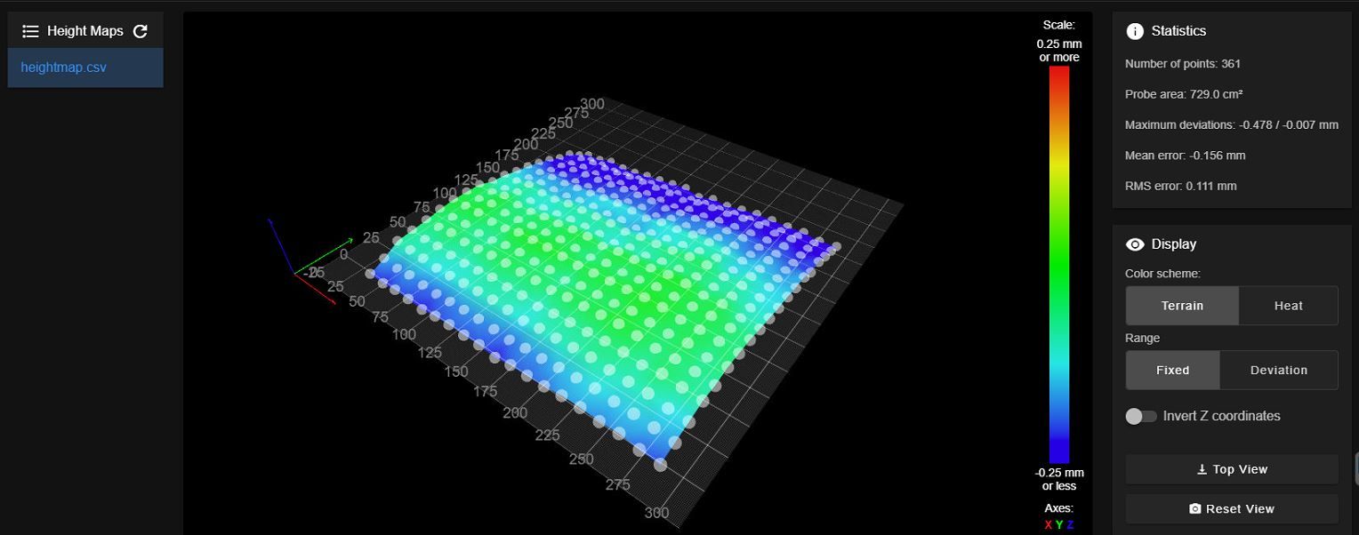
heightmap.csvAs you can see the back side o the bed is lower than the front side so, theoretically, the print should be "detached" from the bed not viceversa, so it looks like the print is "over compensated".
I really can't get a decent print anymore...I've also changed the Z stepper using a 0.9° to see if it provides more accuracy but, as I expected, nothing has changed. I use the original X5S threaded rods for the Z so they can give enough accuracy to compensate correctly....
I repeat I don't know where the problem could be....I'm starting to think to change the VINDA with a BLTOUCH but the problem is that the probing pin would be farther from the nozzle....
Thanks for any suggestion.....
-
-
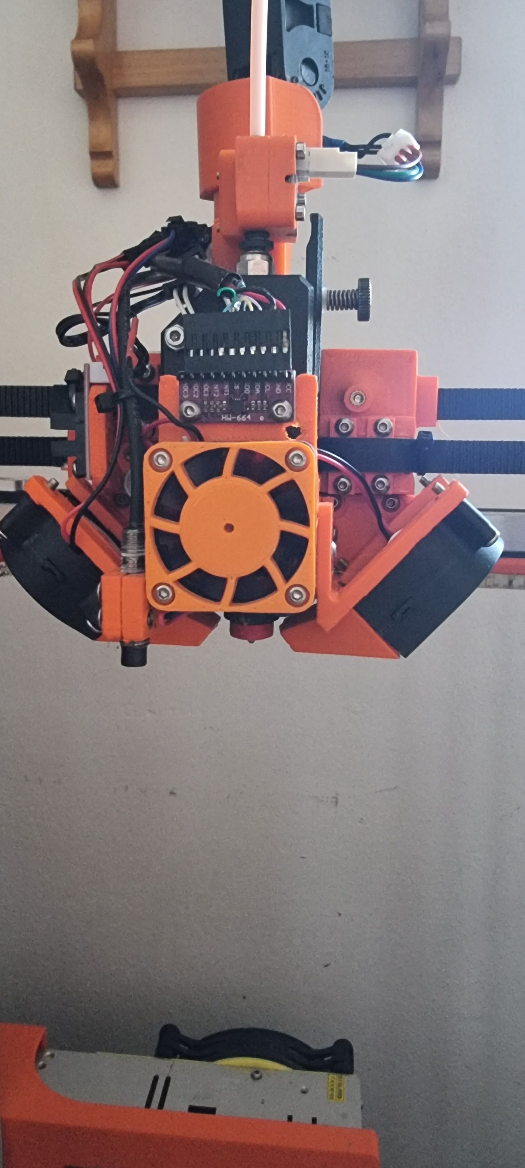
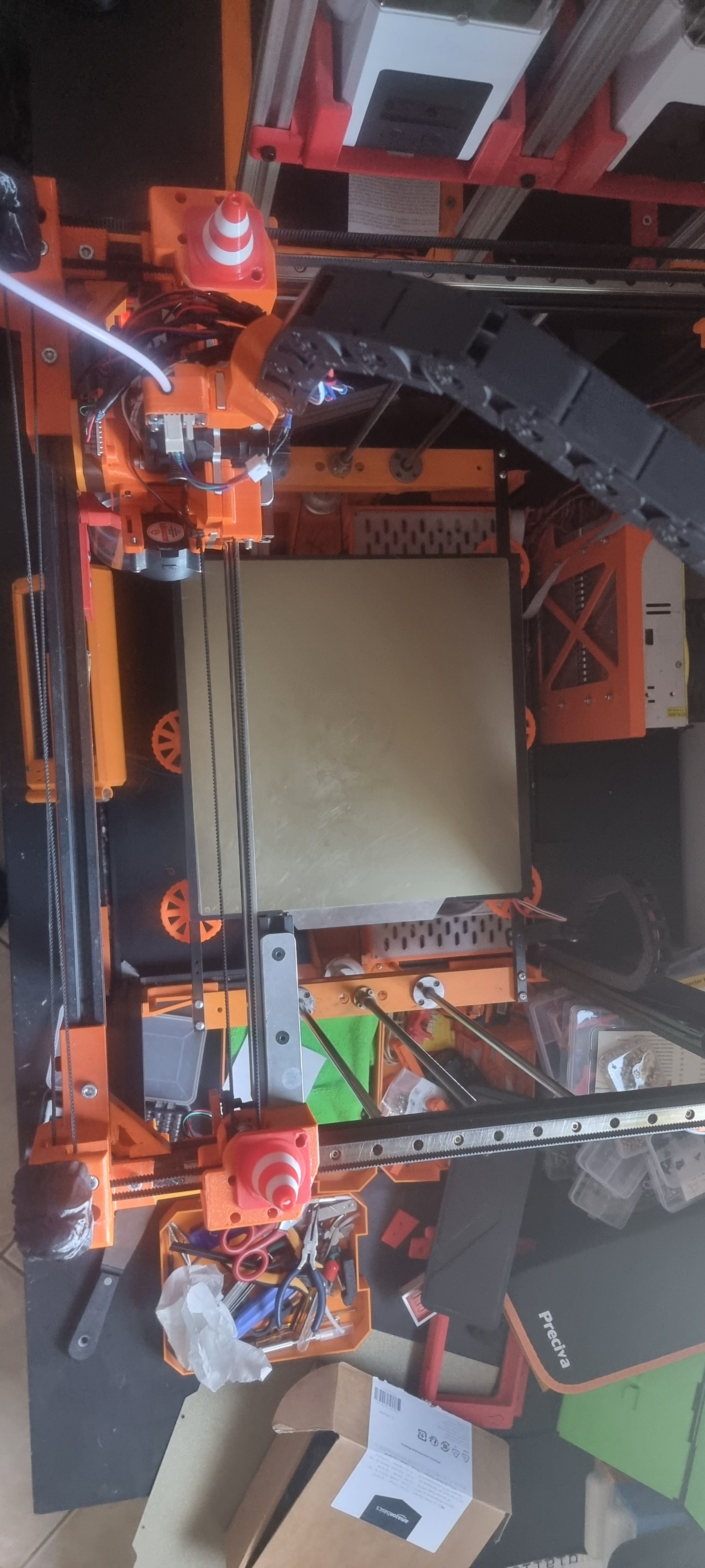
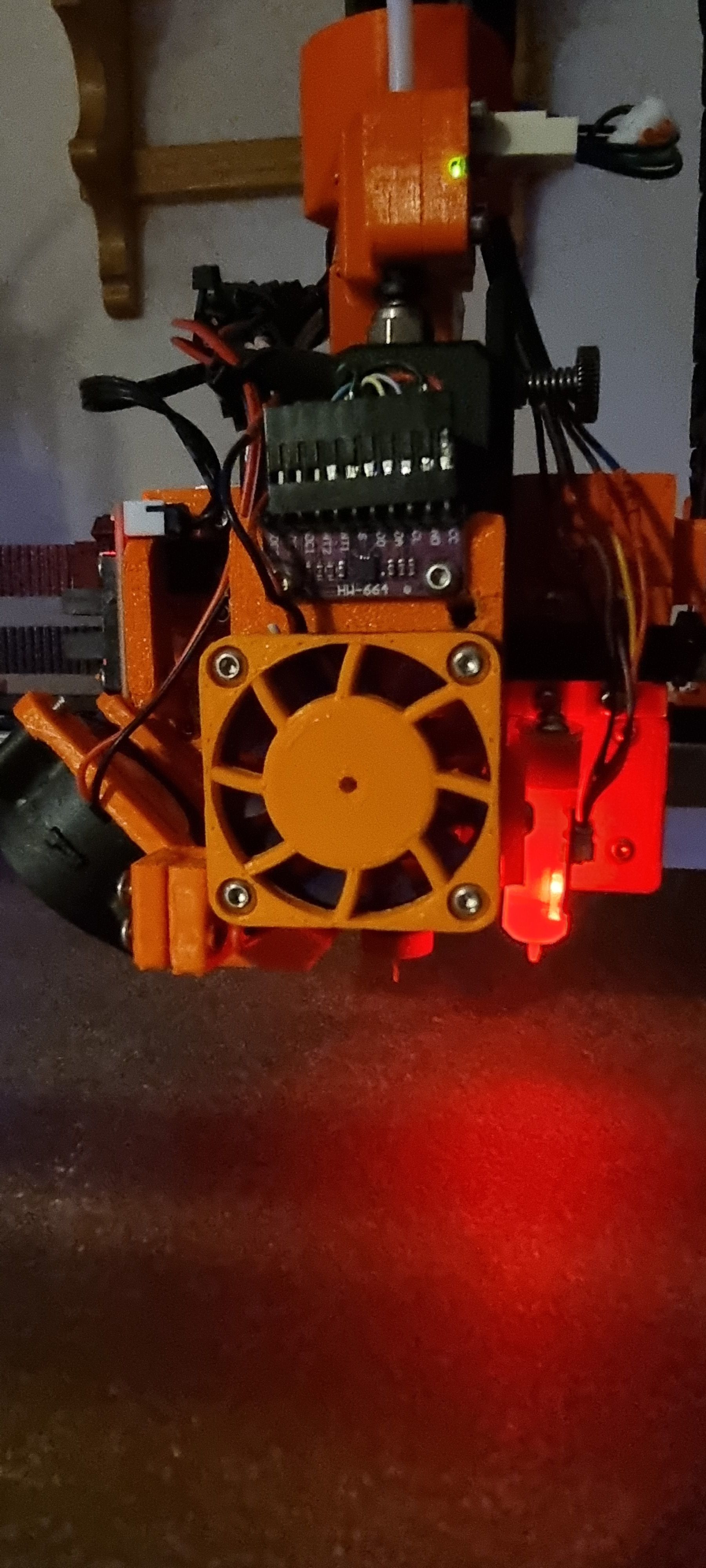
@TheDragonLord Can you post a picture of your print head (so we can see the location of your probe). Can you also post a picture of your printer from above taken with the printhead touching your two homing limit switches so we can see the location of the printhead and the bed.
When you are setting your nozzle offset are you heating the bed and nozzle, if not I would suggest that you do so. I would also suggest that because you have a large X/Y probe offset that after touching the bed with the nozzle and setting Z=0 you should jog your print head so that your probe is now over the same X/Y point you used to set Z=0 before running the G30 S-1 command.
-
@gloomyandy said in Z Offset calculation and Height Map inconsistent:
@TheDragonLord Can you post a picture of your print head (so we can see the location of your probe). Can you also post a picture of your printer from above taken with the printhead touching your two homing limit switches so we can see the location of the printhead and the bed.
When you are setting your nozzle offset are you heating the bed and nozzle, if not I would suggest that you do so. I would also suggest that because you have a large X/Y probe offset that after touching the bed with the nozzle and setting Z=0 you should jog your print head so that your probe is now over the same X/Y point you used to set Z=0 before running the G30 S-1 command.
Here are the photos:
Of couse I have bed and nozzle heated when I set the Z offset and every time I re-do the G30 S-1 the nozzle is always in the same X ad Y position...
-
@TheDragonLord Just to be clear, when you measure the Z offset are you moving the print head so that the probe is over the same location that you touched the bed to set Z=0? That step is not included in the Duet process, I think it should be.
Looking at your printer I would be worried that the drag chain might be causing a slight tilting of the printhead which because of the large probe offset can cause the readings to be off in different parts of the bed. You can probably check for this by repeating the Z offset measurement process at different parts of the bed. So for instance measure the probe z offset close to the corners of the bed and in the centre. It should be the same in all of those locations.
Also if you think that there has been a problem introduced in 3.4.5 then I would suggest switching back to whatever version of the firmware you used before to confirm that the problem goes away.
-
@gloomyandy said in Z Offset calculation and Height Map inconsistent:
@TheDragonLord Just to be clear, when you measure the Z offset are you moving the print head so that the probe is over the same location that you touched the bed to set Z=0? That step is not included in the Duet process, I think it should be.
Looking at your printer I would be worried that the drag chain might be causing a slight tilting of the printhead which because of the large probe offset can cause the readings to be off in different parts of the bed. You can probably check for this by repeating the Z offset measurement process at different parts of the bed. So for instance measure the probe z offset close to the corners of the bed and in the centre. It should be the same in all of those locations.
Also if you think that there has been a problem introduced in 3.4.5 then I would suggest switching back to whatever version of the firmware you used before to confirm that the problem goes away.
I've replaced the VINDA wih a BLTouch, correctly mounted and setted....
now the things go even worst because REGARDLESS what I do the print starts ALWAYS with the nozzle higher than 1mm from the plate and I can't solve this issue even using the baby stepping....I've tried to return to 3.4.4. but same issue....maybe I've destoyed some settings but really I don't know what's happening....could be some PrusaSlicer setting? (I haven't changed anything).I've tried to change slicer, disable the G29 S1 in the start gcode but nothing seems to work....I've tried to set a ridicolous Z offset of 2.5mm in the G31 in config.g but nothing works, with BLTouch the nozzle is ALWAYS very very high from the plate...Also tried differnt gcodes and all of them suffers the same issue....My printer is not working anymore and I really don't understand why....there isn't a logic behind this issue, I haven't changed nothing but the BLTouch to solve the VINDA problems....
I really need help..... here's the config.g with the changes for the BLTouch:
; Configuration file for Duet WiFi (firmware version 3)
; executed by the firmware on start-up
;
; generated by RepRapFirmware Configuration Tool v3.1.4 on Sun Nov 01 2020 08:34:36 GMT+0100 (Ora standard dell’Europa centrale)

; General preferences
G90                                                    ; send absolute coordinates...
M83                                                    ; ...but relative extruder moves
M550 P"DragonCore"                                     ; set printer name
M669 K1                                                ; select CoreXY mode

; Network
M552 S1                                                ; enable network
M586 P0 S1                                             ; enable HTTP
M586 P1 S1                                             ; enable FTP
M586 P2 S1                                             ; enable Telnet

; Drives
M569 P0 S1                                             ; physical drive 0 goes backwards
M569 P1 S1                                             ; physical drive 1 goes backwards
M569 P2 S0                                             ; physical drive 2 goes backwards
M569 P3 S0                                             ; physical drive 3 goes backwards
M569 P4 S0                                             ; physical drive 4 goes backwards
M584 X0 Y1 Z2 E3                                       ; set drive mapping
M350 E16 I0                                        ; configure microstepping without interpolation
M350 X16 Y16 Z16 I1                                    ; configure microstepping with interpolation
M92 X79.8 Y79.8 Z2376.48 E415                    ; set steps per mm
M566 X1200.00 Y1200.00 Z12.00 E6000                 ; set maximum instantaneous speed changes (mm/min) ####################################
M203 X18000.00 Y18000.00 Z360.00 E5000.00      ; set maximum speeds (mm/min) ############################
M201 X9000.00 Y9000.00 Z100.00 E5000.00           ; set accelerations (mm/s^2) ###############################
M906 X1200 Y1200 Z900 E500 I30                       ; set motor currents (mA) and motor idle factor in per cent ###################################e
M84 S30                                                ; Set idle timeout

; Axis Limits
M208 X0 Y-25 Z0 S1                                       ; set axis minima ################################
M208 X313 Y320 Z350 S0                                 ; set axis maxima #########################################

; Endstops
M574 X1 S1 P"xstop"                                    ; configure active-high endstop for low end on X via pin xstop
M574 Y1 S1 P"ystop"                                    ; configure active-high endstop for low end on Y via pin ystop
M574 Z1 S2                                             ; configure Z-probe endstop for low end on Z

; Z-Probe
M950 S0 C"exp.heater3"
;M558 P9 C"^zprobe.in" H5 F120 T6000                    ; set Z probe type to bltouch and the dive height + speeds
M558 P9 C"^zprobe.in" F120 H5 R0.2 T6000 A5 B1
G31 P25 X27 Y-4 Z1.177                                ; set Z probe trigger value, offset and trigger height  ###############################################
;M557 X27:310 Y00:310 S20                                ; define mesh grid #####################################################
M557 X27:310 Y00:310 P4                                ; define mesh grid #####################################################

; Heaters
M308 S0 P"bedtemp" Y"thermistor" T100000 B4092         					; configure sensor 0 as thermistor on pin bedtemp
M950 H0 C"bedheat" T0                                  					; create bed heater output on bedheat and map it to sensor 0
M307 H0 B0 S1.00                                       					; disable bang-bang mode for the bed heater and set PWM limit
M140 H0                                                					; map heated bed to heater 0
M143 H0 S120                                           					; set temperature limit for heater 0 to 120C
M308 S1 P"e0temp" Y"thermistor" T100000 B4725 C7.060000e-8
M950 H1 C"e0heat" T1                                   					; create nozzle heater output on e0heat and map it to sensor 1
M307 H1 B0 S1.00                                       					; disable bang-bang mode for heater  and set PWM limit
M143 H1 S285                                           					; set temperature limit for heater 1 to 280C

; Fans
M950 F0 C"fan0" Q2000                                   ; create fan 0 on pin fan0 and set its frequency
M106 P0 S0 H-1                                         ; set fan 0 value. Thermostatic control is turned off
M950 F1 C"fan1" Q500                                   ; create fan 1 on pin fan1 and set its frequency
M106 P1 S1 H1 T50                                      ; set fan 1 value. Thermostatic control is turned on
M308 S4 Y"mcu-temp" A"MCU"                             ; configure sensor 3 as thermistor on pin e1temp for left stepper
M308 S3 Y"drivers" A"Drivers"  						   ; configure sensor 4 as temperature warning and overheat flags on the TMC2660 on Duet

; =============================================
; = LED FAN                                   =
; =============================================
M950 F11 C"exp.heater4"
M106 P11 S0

; Tools
M563 P0 S"Master" D0 H1 F0                             ; define tool 0
G10 P0 X0 Y0 Z0                                        ; set tool 0 axis offsets
G10 P0 R0 S0                                           ;  set initial tool 0 active and standby temperatures to 0C

; Miscellaneous
M575 P1 S1 B57600                                      ; enable support for PanelDue
M912 P0 S-2.45                                         ; calibrates CPU temp
M501                                                   ; load saved parameters from non-volatile memory

; =========================================================
; =               D R A G O N    C O R E                  =
; =========================================================

; ==================
; = VARIABLES      =
; ==================
global primingExtruderAmount=12

; ==================
; = NOZZLES WIPING =
; ==================
global XWipeEnterCoord=0
global YWipeEnterCoord=0
global XWipeStartCoord=38
;global XWipeEndCoord=77
global XWipeEndCoord=45
global XWipeFinalCoord=147
global YWipeFinalCoord=-25

; ==================
; = FOR PA SETTINGS=
; ==================
;global g_pa_setting       = 0.12        	 ; the current pressure advance setting
;global g_pa_increment      = 0.02        ; the amount to increment the pressure advance setting
;global g_pa_layer_count    = 20         ; For 0.2mm layer height the number of layers to count to cause the incrementing of the pressure advance setting
;global g_pa_layer_count    = 10         ; For 0.6mm layer height the number of layers to count to cause the incrementing of the pressure advance setting
;global g_pa_layer_count    = 30         ; For 0.1mm layer height the number of layers to count to cause the incrementing of the pressure advance setting
;global g_pa_layer_counter  = 0          ; the current layer count
;M572 D0 S{global.g_pa_setting}

; ==================
; = SCREWS POINTS  =
; ==================
M671 X5:310:100:5 Y310:310:5:5 P0.5 ; point1 (5,320), point2 (320,320), point3 (320,5), point4 (5,5)

; ====================
; = FILAMENT SENSOR  =
; ====================
M591 D0 P3 C"e0stop" R10:190 L25.11 E3.0 S1

; =================
; = ACCELEROMETER =
; =================
M955 P0 C"spi.cs4+spi.cs3" I50

; ==================
; = INPUT SHAPING  =
; ==================
M593 P"zvddd" F49

; ======================
; = POWER FAILURE      =
;=======================
M911 S21 R23 P"M913 X0 Y0 G91 M83 G1 Z3 E-5 F1000" ; power failure
This is one of my gcodes just if someone could find an "error" in it:
X5S BMG Direct 4020 Blower BLTouch 0.2.gcode -
Is your drag chain causing the print head to tilt or deform the gantry a small amount when in those areas at the rear?
Are you sure you have the coordinate system correct? -x to the left, +x to the right, -y to the front, +y to the back?
-
@Phaedrux said in Z Offset calculation and Height Map inconsistent:
Is your drag chain causing the print head to tilt or deform the gantry a small amount when in those areas at the rear?
Are you sure you have the coordinate system correct? -x to the left, +x to the right, -y to the front, +y to the back?
the drag chain is very light and has no impact on the gantry...the coordinates are correct, positive X and negative Y...unfortunately theese are not the causes...I really don't understand, it really seems the Z offset hasn't taken in account at all and even the babystepping seems not to work....
-
Baby stepping won't let you go below your configured M208 Z minima. You can make that value slightly negative, but that shouldn't be necesary.
Can you post the results of sending M122 and M98 P"config.g"?
Also post your homing files and bed.g mesh.g if used.You can also try using the manual probe type as a sanity check. This uses the nozzle tip itself and you manually jog it down to touch the bed.
M558 P0
G31 X0 Y0 Z0Then homing and run a mesh as usual and it will prompt you to jog Z when a probe is requested. You may want to reduce your M557 spacing to speed things up.
-
@Phaedrux said in Z Offset calculation and Height Map inconsistent:
Baby stepping won't let you go below your configured M208 Z minima. You can make that value slightly negative, but that shouldn't be necesary.
Can you post the results of sending M122 and M98 P"config.g"?
Also post your homing files and bed.g mesh.g if used.You can also try using the manual probe type as a sanity check. This uses the nozzle tip itself and you manually jog it down to touch the bed.
M558 P0
G31 X0 Y0 Z0Then homing and run a mesh as usual and it will prompt you to jog Z when a probe is requested. You may want to reduce your M557 spacing to speed things up.
M122:
13/12/2022, 09:10:59	M122
=== Diagnostics ===
RepRapFirmware for Duet 2 WiFi/Ethernet version 3.4.5 (2022-11-30 19:36:12) running on Duet WiFi 1.02 or later
Board ID: 08DLM-996RU-N85T0-6JKFJ-3SD6R-9SSHN
Used output buffers: 2 of 26 (20 max)
=== RTOS ===
Static ram: 23836
Dynamic ram: 77976 of which 12 recycled
Never used RAM 7400, free system stack 184 words
Tasks: NETWORK(notifyWait,14.7%,211) ACCEL(notifyWait,0.0%,348) HEAT(notifyWait,0.0%,333) Move(notifyWait,0.0%,363) MAIN(running,83.3%,440) IDLE(ready,1.9%,30), total 100.0%
Owned mutexes: WiFi(NETWORK)
=== Platform ===
Last reset 00:00:50 ago, cause: software
Last software reset at 2022-12-13 09:10, reason: User, GCodes spinning, available RAM 6848, slot 2
Software reset code 0x0003 HFSR 0x00000000 CFSR 0x00000000 ICSR 0x0041f000 BFAR 0xe000ed38 SP 0x00000000 Task MAIN Freestk 0 n/a
Error status: 0x00
Aux0 errors 0,0,0
Step timer max interval 0
MCU temperature: min 27.7, current 28.5, max 28.7
Supply voltage: min 23.9, current 24.0, max 24.2, under voltage events: 0, over voltage events: 0, power good: yes
Heap OK, handles allocated/used 99/7, heap memory allocated/used/recyclable 2048/130/0, gc cycles 0
Events: 0 queued, 0 completed
Driver 0: standstill, SG min n/a
Driver 1: standstill, SG min n/a
Driver 2: standstill, SG min n/a
Driver 3: standstill, SG min n/a
Driver 4: standstill, SG min n/a
Driver 5:
Driver 6:
Driver 7:
Driver 8:
Driver 9:
Driver 10:
Driver 11:
Date/time: 2022-12-13 09:10:58
Cache data hit count 1808673717
Slowest loop: 10.00ms; fastest: 0.19ms
I2C nak errors 0, send timeouts 0, receive timeouts 0, finishTimeouts 0, resets 0
=== Storage ===
Free file entries: 10
SD card 0 detected, interface speed: 20.0MBytes/sec
SD card longest read time 0.6ms, write time 0.0ms, max retries 0
=== Move ===
DMs created 83, segments created 0, maxWait 0ms, bed compensation in use: none, comp offset 0.000
=== MainDDARing ===
Scheduled moves 0, completed 0, hiccups 0, stepErrors 0, LaErrors 0, Underruns [0, 0, 0], CDDA state -1
=== AuxDDARing ===
Scheduled moves 0, completed 0, hiccups 0, stepErrors 0, LaErrors 0, Underruns [0, 0, 0], CDDA state -1
=== Heat ===
Bed heaters 0 -1 -1 -1, chamber heaters -1 -1 -1 -1, ordering errs 0
=== GCodes ===
Segments left: 0
Movement lock held by null
HTTP is idle in state(s) 0
Telnet is idle in state(s) 0
File is idle in state(s) 0
USB is idle in state(s) 0
Aux is idle in state(s) 0
Trigger is idle in state(s) 0
Queue is idle in state(s) 0
LCD is idle in state(s) 0
Daemon is idle in state(s) 0
Autopause is idle in state(s) 0
Code queue is empty
=== Filament sensors ===
Extruder 0: pos 8.44, errs: frame 0 parity 0 ovrun 0 pol 0 ovdue 0
=== Network ===
Slowest loop: 127.54ms; fastest: 0.00ms
Responder states: HTTP(0) HTTP(0) HTTP(0) HTTP(0) FTP(0) Telnet(1)
HTTP sessions: 2 of 8
= WiFi =
Network state is active
WiFi module is connected to access point
Failed messages: pending 0, notready 0, noresp 0
WiFi firmware version 1.27
WiFi MAC address 84:0d:8e:b3:bc:96
WiFi Vcc 3.45, reset reason Turned on by main processor
WiFi flash size 4194304, free heap 24408
WiFi IP address 192.168.1.7
WiFi signal strength -36dBm, mode 802.11n, reconnections 0, sleep mode modem
Clock register 00002002
Socket states: 2 0 0 0 0 0 0 0
M98 P"config.g":
M98 P"config.g"
HTTP is enabled on port 80
FTP is enabled on port 21
TELNET is enabled on port 23
Error: in file macro line 93 column 30: meta command: variable 'primingExtruderAmount' already exists
The error is a nonsense because that variable is declared only once. BUT it's the first declared variable ando so I'm afraid that could be an error in the config.g "above" this declaration. I've commented all the global variables declarations and the error doesn't show up but it does even with only one declaration left
Here's the config.g; Configuration file for Duet WiFi (firmware version 3) ; executed by the firmware on start-up ; ; generated by RepRapFirmware Configuration Tool v3.1.4 on Sun Nov 01 2020 08:34:36 GMT+0100 (Ora standard dell’Europa centrale) ; General preferences G90 ; send absolute coordinates... M83 ; ...but relative extruder moves M550 P"DragonCore" ; set printer name M669 K1 ; select CoreXY mode ; Network M552 S1 ; enable network M586 P0 S1 ; enable HTTP M586 P1 S1 ; enable FTP M586 P2 S1 ; enable Telnet ; Drives M569 P0 S1 ; physical drive 0 goes backwards M569 P1 S1 ; physical drive 1 goes backwards M569 P2 S0 ; physical drive 2 goes backwards M569 P3 S0 ; physical drive 3 goes backwards M569 P4 S0 ; physical drive 4 goes backwards M584 X0 Y1 Z2 E3 ; set drive mapping M350 E16 I0 ; configure microstepping without interpolation M350 X16 Y16 Z16 I1 ; configure microstepping with interpolation M92 X79.8 Y79.8 Z2376.48 E415 ; set steps per mm M566 X1200.00 Y1200.00 Z12.00 E6000 ; set maximum instantaneous speed changes (mm/min) #################################### M203 X18000.00 Y18000.00 Z360.00 E5000.00 ; set maximum speeds (mm/min) ############################ M201 X9000.00 Y9000.00 Z100.00 E5000.00 ; set accelerations (mm/s^2) ############################### M906 X1200 Y1200 Z900 E500 I30 ; set motor currents (mA) and motor idle factor in per cent ###################################e M84 S30 ; Set idle timeout ; Axis Limits M208 X0 Y-25 Z0 S1 ; set axis minima ################################ M208 X313 Y320 Z350 S0 ; set axis maxima ######################################### ; Endstops M574 X1 S1 P"xstop" ; configure active-high endstop for low end on X via pin xstop M574 Y1 S1 P"ystop" ; configure active-high endstop for low end on Y via pin ystop M574 Z1 S2 ; configure Z-probe endstop for low end on Z ; Z-Probe M950 S0 C"exp.heater3" ;M558 P9 C"^zprobe.in" H5 F120 T6000 ; set Z probe type to bltouch and the dive height + speeds M558 P9 C"^zprobe.in" F120 H5 R0.2 T6000 A5 B1 G31 P25 X27 Y-4 Z1.207 ; set Z probe trigger value, offset and trigger height ############################################### ;M557 X27:310 Y00:310 S20 ; define mesh grid ##################################################### M557 X27:310 Y00:310 P4 ; define mesh grid ##################################################### ; Heaters M308 S0 P"bedtemp" Y"thermistor" T100000 B4092 ; configure sensor 0 as thermistor on pin bedtemp M950 H0 C"bedheat" T0 ; create bed heater output on bedheat and map it to sensor 0 M307 H0 B0 S1.00 ; disable bang-bang mode for the bed heater and set PWM limit M140 H0 ; map heated bed to heater 0 M143 H0 S120 ; set temperature limit for heater 0 to 120C M308 S1 P"e0temp" Y"thermistor" T100000 B4725 C7.060000e-8 M950 H1 C"e0heat" T1 ; create nozzle heater output on e0heat and map it to sensor 1 M307 H1 B0 S1.00 ; disable bang-bang mode for heater and set PWM limit M143 H1 S285 ; set temperature limit for heater 1 to 280C ; Fans M950 F0 C"fan0" Q2000 ; create fan 0 on pin fan0 and set its frequency M106 P0 S0 H-1 ; set fan 0 value. Thermostatic control is turned off M950 F1 C"fan1" Q500 ; create fan 1 on pin fan1 and set its frequency M106 P1 S1 H1 T50 ; set fan 1 value. Thermostatic control is turned on M308 S4 Y"mcu-temp" A"MCU" ; configure sensor 3 as thermistor on pin e1temp for left stepper M308 S3 Y"drivers" A"Drivers" ; configure sensor 4 as temperature warning and overheat flags on the TMC2660 on Duet ; ============================================= ; = LED FAN = ; ============================================= M950 F11 C"exp.heater4" M106 P11 S0 ; Tools M563 P0 S"Master" D0 H1 F0 ; define tool 0 G10 P0 X0 Y0 Z0 ; set tool 0 axis offsets G10 P0 R0 S0 ; set initial tool 0 active and standby temperatures to 0C ; Miscellaneous M575 P1 S1 B57600 ; enable support for PanelDue M912 P0 S-2.45 ; calibrates CPU temp M501 ; load saved parameters from non-volatile memory ; ========================================================= ; = D R A G O N C O R E = ; ========================================================= ; ================== ; = VARIABLES = ; ================== global primingExtruderAmount=12 ; ================== ; = NOZZLES WIPING = ; ================== global XWipeEnterCoord=0 global YWipeEnterCoord=0 global XWipeStartCoord=38 ;global XWipeEndCoord=77 global XWipeEndCoord=45 global XWipeFinalCoord=147 global YWipeFinalCoord=-25 ; ================== ; = FOR PA SETTINGS= ; ================== ;global g_pa_setting = 0.12 ; the current pressure advance setting ;global g_pa_increment = 0.02 ; the amount to increment the pressure advance setting ;global g_pa_layer_count = 20 ; For 0.2mm layer height the number of layers to count to cause the incrementing of the pressure advance setting ;global g_pa_layer_count = 10 ; For 0.6mm layer height the number of layers to count to cause the incrementing of the pressure advance setting ;global g_pa_layer_count = 30 ; For 0.1mm layer height the number of layers to count to cause the incrementing of the pressure advance setting ;global g_pa_layer_counter = 0 ; the current layer count ;M572 D0 S{global.g_pa_setting} ; ================== ; = SCREWS POINTS = ; ================== M671 X5:310:100:5 Y310:310:5:5 P0.5 ; point1 (5,320), point2 (320,320), point3 (320,5), point4 (5,5) ; ==================== ; = FILAMENT SENSOR = ; ==================== M591 D0 P3 C"e0stop" R10:190 L25.11 E3.0 S1 ; ================= ; = ACCELEROMETER = ; ================= M955 P0 C"spi.cs4+spi.cs3" I50 ; ================== ; = INPUT SHAPING = ; ================== M593 P"zvddd" F49 ; ====================== ; = POWER FAILURE = ;======================= M911 S21 R23 P"M913 X0 Y0 G91 M83 G1 Z3 E-5 F1000" ; power failureI've made a trial and phisically lowered the BLTouch by about 1mm....well, after that the nozzle raises from the plate about of another 1mm....it looks like the Z offset is "added" rather than "subtracted" from the nozzle height or that the BLTouch gives an "inverted" value....I think I've made some stupid typing error somewhere but I can't realize where
In an case here's my bed.g:
; bed.g

G28 XY; home
G28 Z

M401 ; deploy Z probe

G30 P0 X27 Y310 Z-99999 ; probe near an adjusting screw
G30 P1 X155 Y310 Z-99999 ; probe near an adjusting screw
G30 P2 X310 Y310 Z-99999 ; probe near an adjusting screw
G30 P3 X310 Y0 Z-99999 ; probe near an adjusting screw
G30 P4 X155 Y0 Z-99999 ; probe near an adjusting screw
G30 P5 X27 Y0 Z-99999 S-1; probe near an adjusting screw and report adjustments needed

M402 ; retract probe
I don't have a mesh.g
EDIT:
It's something related to the BLTouch itself because re-replacing it with the VINDA the Z Offset problem doesn't occur again. Of course it remains the problem about the inconsistent bed mesh. Some idea about how I can make the BLtouch working? -
@TheDragonLord said in Z Offset calculation and Height Map inconsistent:
I've made a trial and phisically lowered the BLTouch by about 1mm....well, after that the nozzle raises from the plate about of another 1mm....it looks like the Z offset is "added" rather than "subtracted" from the nozzle height or that the BLTouch gives an "inverted" value....I think I've made some stupid typing error somewhere but I can't realize where
The BLtouch should be mounted such that the base of the probe body is approximately 8mm above the nozzle tip. This should lead to a trigger height of ~2mm. This is the range recommended by Antclabs themselves to ensure accurate probing and clearance of the pin.
Increasing the probe offset moves the nozzle closer to the bed, reducing it moves it farther away.
Did you try the M558 P0 trick?
-
@Phaedrux said in Z Offset calculation and Height Map inconsistent:
@TheDragonLord said in Z Offset calculation and Height Map inconsistent:
I've made a trial and phisically lowered the BLTouch by about 1mm....well, after that the nozzle raises from the plate about of another 1mm....it looks like the Z offset is "added" rather than "subtracted" from the nozzle height or that the BLTouch gives an "inverted" value....I think I've made some stupid typing error somewhere but I can't realize where
The BLtouch should be mounted such that the base of the probe body is approximately 8mm above the nozzle tip. This should lead to a trigger height of ~2mm. This is the range recommended by Antclabs themselves to ensure accurate probing and clearance of the pin.
Increasing the probe offset moves the nozzle closer to the bed, reducing it moves it farther away.
Did you try the M558 P0 trick?
Hi, no I didn't, I had few time today and I've mainly focused on try to understand how to solve the problem with the BLtouch...in the end I had to re-mount the vinda because I couldn't get rid of the error and the vinda works in terms of z offset....I didn't know about the 8mm I've always used it with almost 3-5mm...tomorrow I'll see if I have enough vertical room to mount it at about 8mm from the nozzle...thanks!