G32 causing low 4 corners in G29
-
Hi All,
I've been doing some tweaks on my printer as my 4 lead screws just weren't holding and was causing me to set Z0, probe offset and MBL/ABL before every print. So I removed the springs and put on silicon brackets which keep it nice and tight.
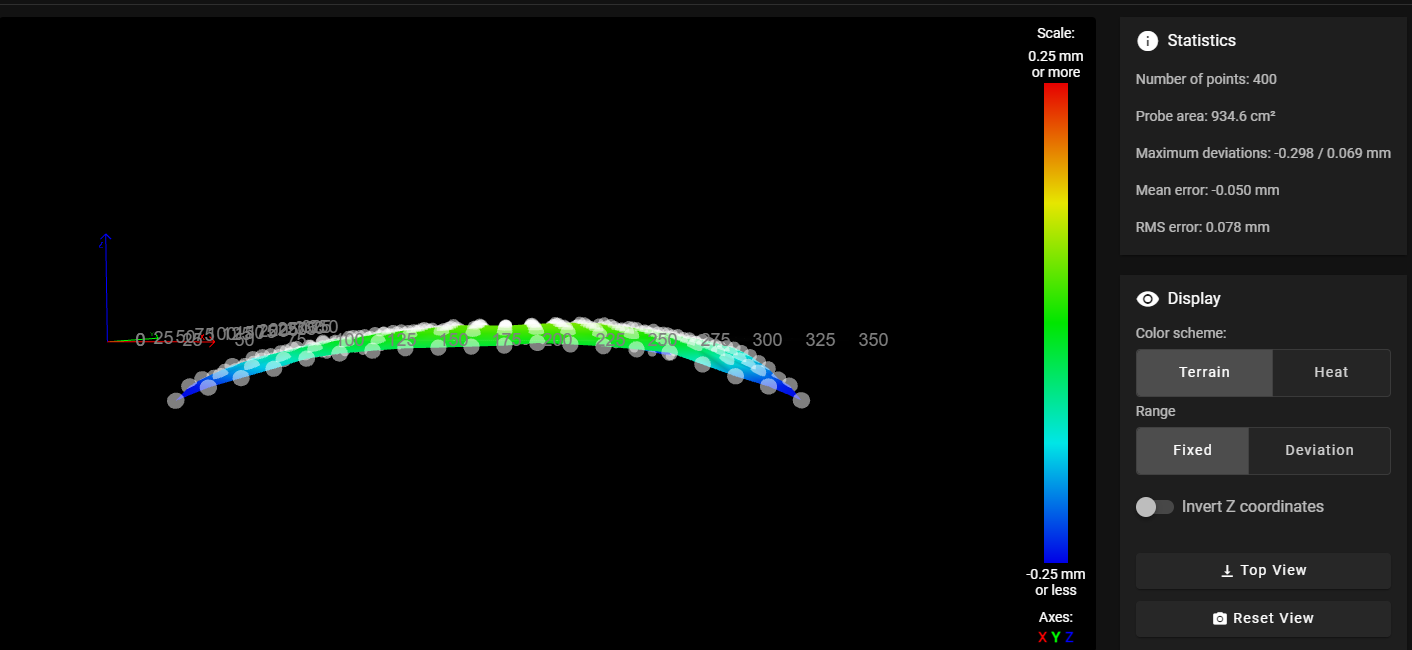
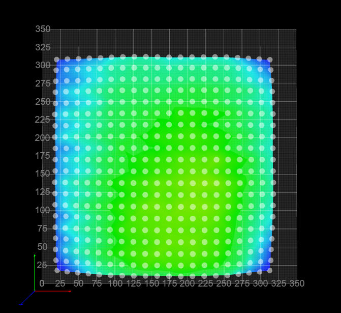
I was able to adjust everything so that when I run G32, I get either 0.00 or 0.001 deviation which is great for the next G29 run. BUT, when I run G29, my 4 corners are all visually lower which I find odd, especially of G32 is telling me these are all level.
So after a few attempts to MBL and ABL and getting the same result in my Heightmap, I wanted to see if I could get some suggestions from here.
I have a Ender 5 Plus with 4 bed screws and 2 Z lead screws on independent motors.
Duet 2 Wifi
RepRap version 3.4.1Here are some screenshots from my Heightmap:


And this my bed.g file
G28 Z; home
G30 P0 X{global.probe_offset_x} + {global.fl_screw_x} Y{global.probe_offset_y} + {global.fl_screw_y} Z-9999 ; Front-Left
G30 P1 X{global.probe_offset_x} + {global.fr_screw_x} Y{global.probe_offset_y} + {global.fr_screw_y} Z-9999 ; Front-Right
G30 P3 X{global.probe_offset_x} + {global.bl_screw_x} Y{global.probe_offset_y} + {global.bl_screw_y} Z-9999 ; Back-Left
G30 P2 X{global.probe_offset_x} + {global.br_screw_x} Y{global.probe_offset_y} + {global.br_screw_y} Z-9999 S4 ; Back-Right
And here's mesh.g
; ######################################################
;mesh g - manually configured
; ######################################################
M98 P"configs/zhome_config.g" ; configure z=0 datum (this still confuses me on how this is set)

; ######################################################
; Probe bed and create Heightmap
; Duet automatically adds the probe offset to x,y, so remember to calculate this into the below
; ######################################################
M561 ; clear any bed transform
G28 Z
M557 X12.5:320 Y10:314 P20
G29 S0 ; probe and save height map
And the associated zhome_config.g
G90 ; absolute moves

; move probe to center of bed
G1 X{((move.axes[0].max + move.axes[0].min) / 2) - sensors.probes[0].offsets[0]}, Y{((move.axes[1].max + move.axes[1].min) / 2) - sensors.probes[0].offsets[1]}, F{global.g_axes_speeds}

M558 F900
G30             ; home Z by probing the bed
G90             ; absolute positioning
G1 Z{global.g_move_forward} F{global.g_axes_speeds}      ; lift Z to set position
And here's homez.g just in case
; ######################################################
; homez.g - called to home the Z axis
; ######################################################

G91              ; relative positioning
G1 H2 Z{global.g_move_forward} F{global.g_axes_speeds}   ; lift Z relative to current position
G90              ; absolute positioning

; ######################################################
; Run z-home as per homeall, bed and mesh configurations
; ######################################################
M98 P"configs/zhome_config.g"
And finally my config.g jsut incase this is needed as well
; Configuration file for Duet WiFi (firmware version 3)
; executed by the firmware on start-up

; ######################################################
; General preferences
; ######################################################
G90                                                ; send absolute coordinates...
M83                                                ; ...but relative extruder moves
M550 P"Stargate SG-1 - Jackson"                    ; set printer name

; ######################################################
; Global Variables
; ######################################################

global g_move_forward        = 10          ; can be used to always move Z to known height
global g_move_back           = -{global.g_move_forward}          ; can be used to always move Z to known height
global g_axes_speeds		 = 8000 ; Speeds to move axes during homing

; Z-Lead Screw Positions
global l_zlead_screw_x		 = 57
global r_zlead_screw_x		 = 353
global zlead_screw_y		 = 217

; 4-P Bed Levelling Positions
global fl_screw_x		 = 52
global fl_screw_y		 = 81
global fr_screw_x		 = 349
global fr_screw_y		 = 81
global bl_screw_x		 = 52
global bl_screw_y		 = 338
global br_screw_x		 = 349
global br_screw_y		 = 338

global g_print_end_mode      = "HEAT OFF" ; determines if heaters are turned off when print is done
global g_map_mode            = "FULL"     ; determines which kind of height map is created/loaded
global g_probe_mode          = "TWO"      ; determines if z proving used consecutive or averaging
global g_level_mode          = "3PT"      ; determines if 3 or 4 points are used for leveling

; BL-Touch Probe Offsets
global probe_offset_x		 = -30		  ; BL Touch X offset
global probe_offset_y		 = -36		  ; BL Touch Y offset
global probe_offset_z		 = 3.085	  ; BL Touch Z offset

; E-Step Settings
global e_steps			= 393.64774

; ######################################################
; Network
; ######################################################
M552 S1                                            ; enable network
M586 P0 S1                                         ; enable HTTP
M586 P1 S0                                         ; disable FTP
M586 P2 S0                                         ; disable Telnet

; ######################################################
; Stepper Drives
; ######################################################
M569 P0 S0                                         ; X drive 0 goes backwards
M569 P1 S1                                         ; Y drive 1 goes backwards
M569 P2 S1                                         ; Z1 drive 2 goes forwards
M569 P3 S0                                         ; E drive 3 goes backwards
M584 X0 Y1 Z2 E3                                   ; set drive mapping

; ######################################################
; Movement
; ######################################################
M350 X16 Y16 Z16 E16 I1                            ; configure microstepping with interpolation
M92 X80.00 Y80.00 Z800.00 E{global.e_steps}        ; set steps per mm
M566 X900.00 Y900.00 Z300.00 E2000.00 P1           ; set maximum instantaneous speed changes (mm/min)
M203 X6000.00 Y6000.00 Z900.00 E6000.00            ; set maximum speeds (mm/min)
M201 X3500.00 Y3500.00 Z3500.00 E3500.00           ; set accelerations (mm/s^2) 200
M906 X800 Y800 Z800 E1200 I30                      ; set motor currents (mA) and motor idle factor in per cent
M84 S30                                            ; Set idle timeout

; ######################################################
; Pressure Advance
; ######################################################
;M572 D0 S0.25

; ######################################################
; Axis Min/Max
; ######################################################
M208 S1 X0 Y0 Z-2                                 ; set axis minima
M208 S0 X350 Y350 Z400                             ; set axis maxima

; ######################################################
; Endstops
; ######################################################
M574 X2 S1 P"xstop"                                ; configure active-high endstop for low end on X via pin xstop
M574 Y2 S1 P"ystop"                                ; configure active-high endstop for low end on Y via pin ystop
M574 Z1 S2                                         ; configure Z-probe endstop for low end on Z

; ######################################################
; Kinematics
; ######################################################
M669 K0

; ######################################################
; Custom Probe config file
; ######################################################
M98 P"configs/probe_config.g"                         ; Config settings for my BL Touch probe

; ######################################################
; Heaters
; ######################################################
M308 S0 P"bedtemp" Y"thermistor" T100000 B4138     ; configure sensor 0 as thermistor on pin bedtemp
M950 H0 C"bedheat" T0                              ; create bed heater output on bedheat and map it to sensor 0
M307 H0 B0 S1.00                                   ; disable bang-bang mode for the bed heater and set PWM limit
M140 H0                                            ; map heated bed to heater 0
M143 H0 S150                                       ; set temperature limit for heater 0 to 120C
M308 S1 P"e0temp" Y"thermistor" T100000 B4725 C7.060000e-8      ; configure sensor 1 as thermistor on pin e0temp
M950 H1 C"e0heat" T1                               ; create nozzle heater output on e0heat and map it to sensor 1
M307 H1 B0 S1.00                                   ; disable bang-bang mode for heater  and set PWM limit
M143 H1 S300                                       ; set temperature limit for heater 1 to 300C

; ######################################################
; Fans
; ######################################################
M950 F0 C"nil"									   ; Free up pin F0
M950 F0 C"fan1" Q500							   ; Assign Fan0 for Prusa Slicer and default for other slicers
M106 P0 S0 H-1
M950 F1 C"nil"									   ; Free up pin F0
M950 F1 C"fan0" Q500                               ; create fan 0 on pin fan3 and set its frequency
M106 P1 S1 H1 T80                                  ; set fan 1 value. Thermostatic control is turned on

; ######################################################
; Tools
; ######################################################
M563 P0 D0 H1 F0                                   ; define tool 0
G10 P0 X0 Y0 Z0                                    ; set tool 0 axis offsets
G10 P0 R0 S0                                       ; set initial tool 0 active and standby temperatures to 0C

; ######################################################
; Probe points for my 2x Z Lead Screws
; ######################################################
;M671 X{global.fl_screw_x}:{global.fr_screw_x}:{global.bl_screw_x}:{global.br_screw_x} Y{global.fl_screw_y}:{global.fr_screw_y}:{global.bl_screw_y}:{global.br_screw_y}
M671 X30:310:30:310 Y76.8:76.8:338:338

; ######################################################
; Custom Configurations
; ######################################################

; Filament Runout Sensor
M591 D0 P1 C"e0stop" S1

; TFT Display Config
M575 P1 S1 B57600

; Miscellaneous
M911 S10 R11 P"M913 X0 Y0 G91 M83 G1 Z3 E-5 F1000" ; set voltage thresholds and actions to run on power loss
M501                                               ; load saved parameters from non-volatile memory
Would love some suggestions if someone has any?
Thanks in advance!
Cheers
Tim -
@TimsWorkshop it's quite possible that's correct. I don't have fancy tools to be able to measure things like this so I improvise.
I'll use a gauge block or 123 block and put it on the bed and move the bed and gantry around to see the clearance between the block and the gantry arm. Even those small distances create noticeable effects. In one spot it will be perfectly flush and you'll hear a gentle whoosh as the two surfaces glide against each other, where a different location they'll crash or not even touch.
If you get creative, you can confirm if it's the bed or not.
-
Thanks @gnydick - Definitely a few things for me to tweak and after further reading of the documentation, the 3 points are levelling off the first point so I believe that is why those 4 probe points are all similar but the bed is more center.
Once this print finishes, going to spend some time getting that first point flush with the rest of the bed by loosening the knobs and running smaller G29 probes to get it more aligned and then once I'm happy, going to run another P20 mesh and see how we go.
-
@TimsWorkshop what is the bed material? How firmly fixed is the bed to the frame? Are you doing the mesh when the bed is hot? To me it looks more like thermal expansion is causing the whole bed to bow.
Ian
-
@TimsWorkshop said in G32 causing low 4 corners in G29:
G30 P0 X{global.probe_offset_x} + {global.fl_screw_x} Y{global.probe_offset_y} + {global.fl_screw_y} Z-9999 ; Front-Left
I'm pretty sure that the X and Y parameters of G30 refer to the probe position and not the nozzle (so the offset is already being taken into account). You should be able to test this easily to check. I doubt if this is causing the problems you are seeing, but probably best to avoid the confusion.