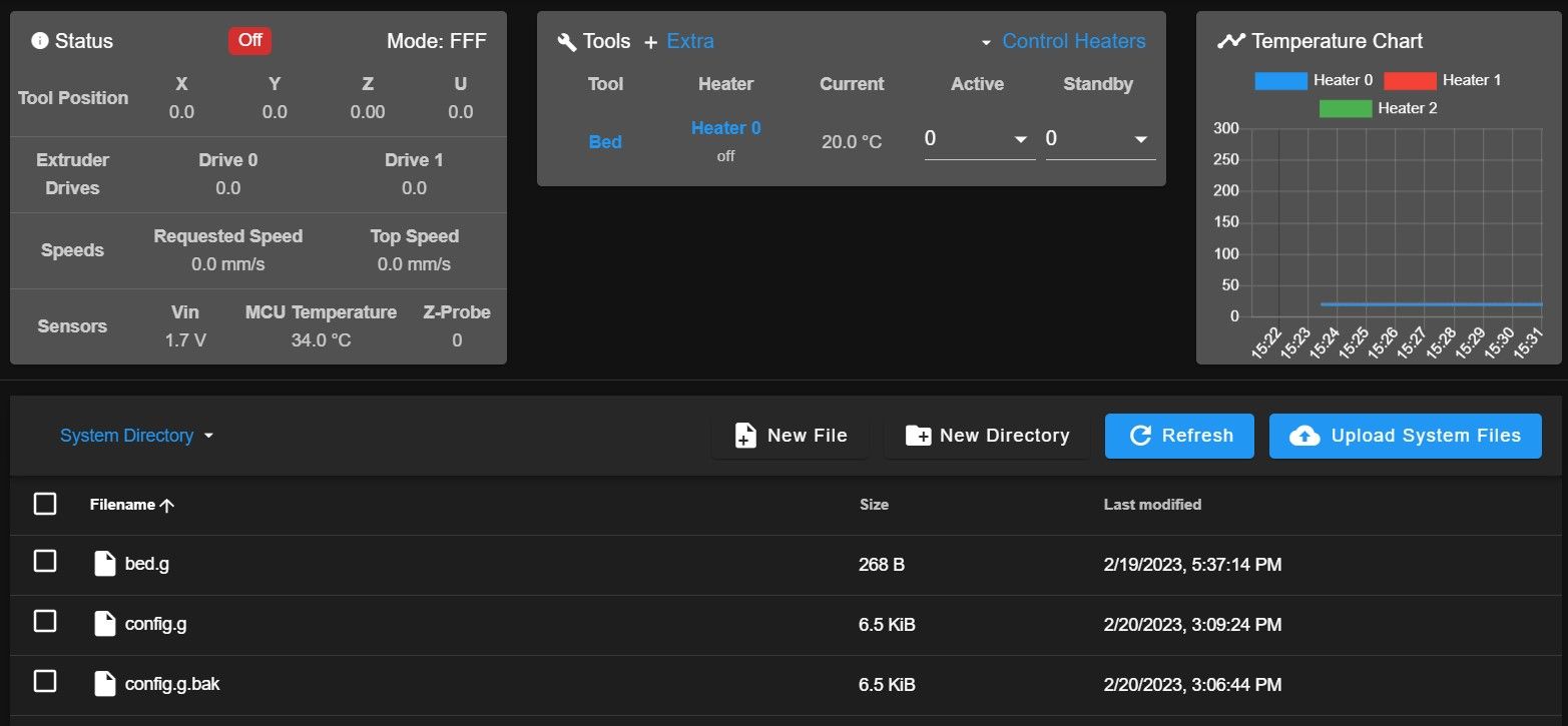
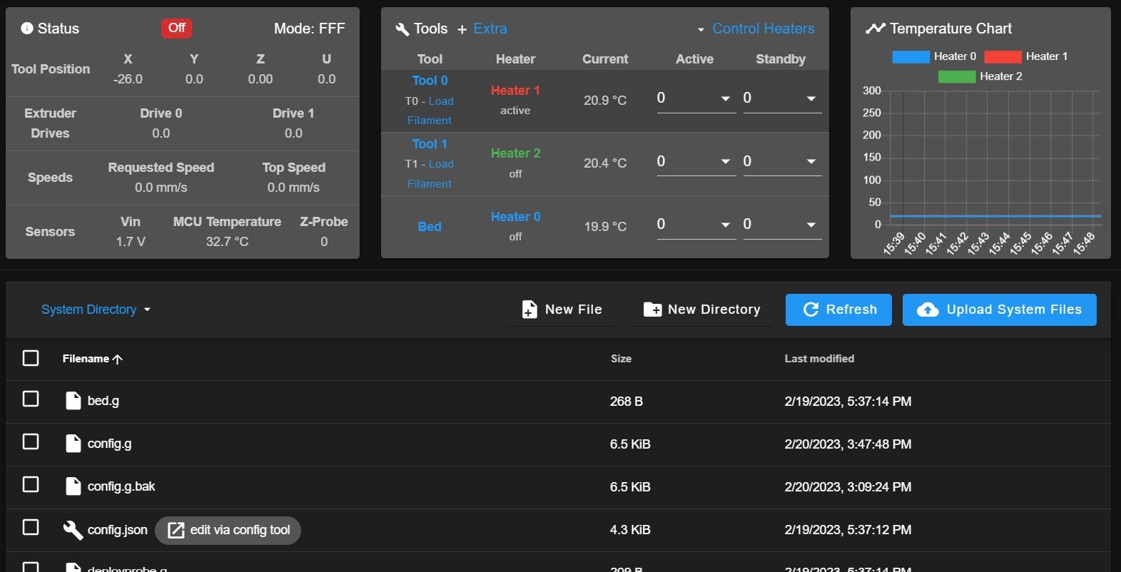
Hotends not showing in DWC
-
My Hotends are not showing in the tools section of my DWC. After hours of research I can't seem to find a solution. I'm fairly certain its the tool section of my config.g. Firmware version 3.4.5. Here is my current config. Keep in mind, this is a new build and has not yet been run. Any guidance is greatly appreciated. TYIA!

; Configuration file for Duet WiFi (firmware version 3.3)
; executed by the firmware on start-up
;
; generated by RepRapFirmware Configuration Tool v3.3.15 on Sun Feb 19 2023 17:01:06 GMT-0500 (Eastern Standard Time); General preferences
G21 ; work in milimeters
G90 ; send absolute coordinates...
M83 ; ...but relative extruder moves
M550 P"IDEX" ; set printer name
M111 S0 ; debug off; Network
M552 S1 ; enable network
M586 P0 S1 ; enable HTTP
M586 P1 S1 ; enable FTP
M586 P2 S0 ; disable Telnet
M575 P1 B57600 S1 ; enable support for PanelDue; Drives
M569 P0 S1 ; physical drive 0 goes forwards - X stepper
M569 P1 S1 ; physical drive 1 goes forwards - Z stepper (left)
M569 P2 S1 ; physical drive 2 goes forwards - Z stepper (right)
M569 P3 S1 ; physical drive 3 goes forwards - E0 stepper
M569 P6 S1 ; physical drive 6 goes forwards - Y stepper (left)
M569 P7 S1 ; physical drive 7 goes forwards - Y stepper (right)
M569 P8 S1 ; physical drive 8 gows forwards - U stepper
M569 P9 S1 ; physical drive 9 goes forwards - E1 stepper
M584 X0 Y6:7 Z1:2 U8 E3:9 ; set drive mapping
M350 X16 Y16 Z16 U16 E16:16 I1 ; configure microstepping with interpolation
M92 X80.00 Y80.00 Z800.00 U80.00 E400.00:400.00 ; set steps per mm
M566 X900.00 Y900.00 Z60.00 U900.00 E120.00:120.00 ; set maximum instantaneous speed changes (mm/min) - jerk
M203 X6000.00 Y6000.00 Z180.00 U6000.00 E1200.00:1200.00 ; set maximum speeds (mm/min)
M201 X500.00 Y500.00 Z20.00 U500.00 E250.00:250.00 ; set accelerations (mm/s^2)
M906 X2300 Y2300 Z2300 U2300 E600:600 I30 ; set motor currents (mA) and motor idle factor in per cent
M84 S30 ; Set idle timeout; Axis Limits
M208 X0 Y0 Z0 S1 ; set axis minima
M208 X290 Y300 Z300 S0 ; set axis maxima; Endstops
M574 X1 S1 P"e1stop" ; configure switch-type (e.g. microswitch) endstop for low end on X via pin e1stop
M574 U1 S1 P"exp.e6stop" ; configure switch-type (e.g. microswitch) endstop for high end on U via pin exp.e6stop
M574 Y1 S1 P"exp.e5stop" ; configure switch-type (e.g. microswitch) endstop for low end on Y via pin exp.e5stop
M574 Z1 S2 ; configure Z-probe endstop for low end on Z; BLTouch
M950 S0 C"duex.pwm1" ; create servo pin 0 for BLTouch
M558 P9 C"^zprobe.in" H5 F120 T6000 ; set Z probe type to bltouch, connected to zprobe.in and the dive height + speeds
G31 P500 X-31 Y-14.5 Z2.5 ; set Z probe trigger value, offset and trigger height
M557 X20:270 Y20:280 S50 ; define mesh grid; Heaters
M308 S0 P"duex.e4temp" Y"thermistor" T100000 B3950 ; configure sensor 0 as thermistor on pin duex.e4temp
M950 H0 C"bedheat" T0 ; create bed heater output on bedheat and map it to sensor 0
M307 H0 B1 S1.00 ; enable bang-bang mode for the bed heater and set PWM limit
M140 H0 ; map heated bed to heater 0
M143 H0 S120 ; set temperature limit for heater 0 to 120C
M308 S1 P"e0temp" Y"thermistor" T100000 B4725 C7.06e-8 ; configure sensor 1 as thermistor on pin e0temp
M950 H1 C"e0heat" T1 ; create nozzle heater output on e0heat and map it to sensor 1
M307 H1 B0 S1.00 ; disable bang-bang mode for heater and set PWM limit
M143 H1 S300 ; set temperature limit for heater 1 to 300C
M308 S2 P"duex.e3temp" Y"thermistor" T100000 B4725 C7.06e-8 ; configure sensor 2 as thermistor on pin duex.e3temp
M950 H2 C"duex.e6heat" T2 ; create nozzle heater output on duex.e6heat and map it to sensor 2
M307 H2 B0 S1.00 ; disable bang-bang mode for heater and set PWM limit
M143 H2 S300 ; set temperature limit for heater 2 to 300C; Fans
M950 F0 C"fan0" Q500 ; create fan 0 on pin fan0 and set its frequency
M106 P0 S0 H-1 ; set fan 0 value. Thermostatic control is turned off
M950 F1 C"fan1" Q500 ; create fan 1 on pin fan1 and set its frequency
M106 P1 S1 H1 T45 ; set fan 1 value. Thermostatic control is turned on
M950 F2 C"duex.fan3" Q500 ; create fan 2 on pin duex.fan3 and set its frequency
M106 P2 S0 H-1 ; set fan 2 value. Thermostatic control is turned off
M950 F3 C"duex.fan4" Q500 ; create fan 3 on pin duex.fan4 and set its frequency
M106 P3 S1 H2 T45 ; set fan 3 value. Thermostatic control is turned on; Tools
M563 P0 D3 H1 F0 ; define tool 0
G10 P0 X-26 Y0 Z0 ; set tool 0 axis offsets
G10 P0 R0 S0 ; set initial tool 0 active and standby temperatures to 0C
M563 P1 D9 H2 F2 ; define tool 1
G10 P1 X30 Y0 Z0 ; set tool 1 axis offsets
G10 P1 R0 S0 ; set initial tool 1 active and standby temperatures to 0C; Custom settings are not defined
; Miscellaneous
T0 ; select first tool -
@SonnyD1 your driver mapping on the tools is wrong. The first one should be D0 not D3 and the second one should be D1 and not D9.
The driver numbers for the extruders start at 0 and you only have 2 extruders mapped with M584 -
@jay_s_uk ok I figured it had to be something like that. My confusion was I thought it wanted driver location on the board. Lemme switch it and I'll let ya know if it works. Thank you for the reply.
-
@jay_s_uk
 Thank you very much. Been tryin to figure that out for a couple hours now.
 -
undefined Phaedrux marked this topic as a question 21 Feb 2023, 04:08
-
undefined Phaedrux has marked this topic as solved 21 Feb 2023, 04:08