Like this?
Best posts made by SonnyD1
-
RE: Input Shapingposted in General Discussion
@jay_s_uk Apparently that was the issue. I bought a USB 3.0 cable and made it up and now its working. Don't know what to do with that data yet but thats a different issue. I'm making progress thanks to the help. Thank you.
-
RE: IDEX U Axis calibrationposted in General Discussion
@droftarts adding a code example for the G10 showing the offsets and explaining how one get them. I’m any case, I’m complete I think.

-
RE: Configuring Multiple Probes/Endstopsposted in General Discussion
@droftarts They are both named correctly IAW your instructions. Here are the files:
; deployprobe0.g
; called to deploy a physical Z probe
;
; generated by RepRapFirmware Configuration Tool v3.5.4 on Sat Aug 10 2024 17:00:40 GMT-0400 (Eastern Daylight Time)

M280 P0 S10	; deploy BLTouch
; retractprobe0.g ; called to retract a physical Z probe ; ; generated by RepRapFirmware Configuration Tool v3.5.4 on Sat Aug 10 2024 17:00:41 GMT-0400 (Eastern Daylight Time) M280 P0 S90 ; retract BLTouchI might have a bad crimp. I'm going to redo the connection.
@droftarts said in Configuring Multiple Probes/Endstops:
What reading for the Z probe is reported in DWC?
Where do I find this? Dashboard?
UPDATE: I found the issue. Conducting further tests to confirm. I must have had a bad crimp/connection. I made a whole new wire and now it deploys on command. The connectors on the Roto toolboard are so tiny that crimps are kinda tough. So much as a couple frayed wires and ya lose continuity.
-
RE: I am at a lossposted in General Discussion
@Phaedrux so that was one thing I just figured out. I unplugged one motor and homed Y. I repeated this for each motor and discovered how the obvious escapes me sometimes. The motors are mirrored so obviously one would be backwards. Fixed that now moving on. Still trying to get a complete homing cycle. Thank you very much for the reply.
-
RE: WIFI Antenna Mountingposted in General Discussion
@Phaedrux Yes I found it. I had two wires swapped on the U axis endstop. Thank you very much. I'm still not up and running but its progress. WIFI Module fires right up now.
-
RE: Warning: Driver 1 warning: over temperature warningposted in General Discussion
@moth4017 so I lowered it to 1900. Repeated the G32 that was triggering the error and it completed this time. I'm pretty sure that will be enough current. If not, now I know I will have to add additional cooling to the boards. I may end up doing that anyway. Thank you for the help but I think you've solved my issue for now.
-
RE: Warning: Driver 1 warning: over temperature warningposted in General Discussion
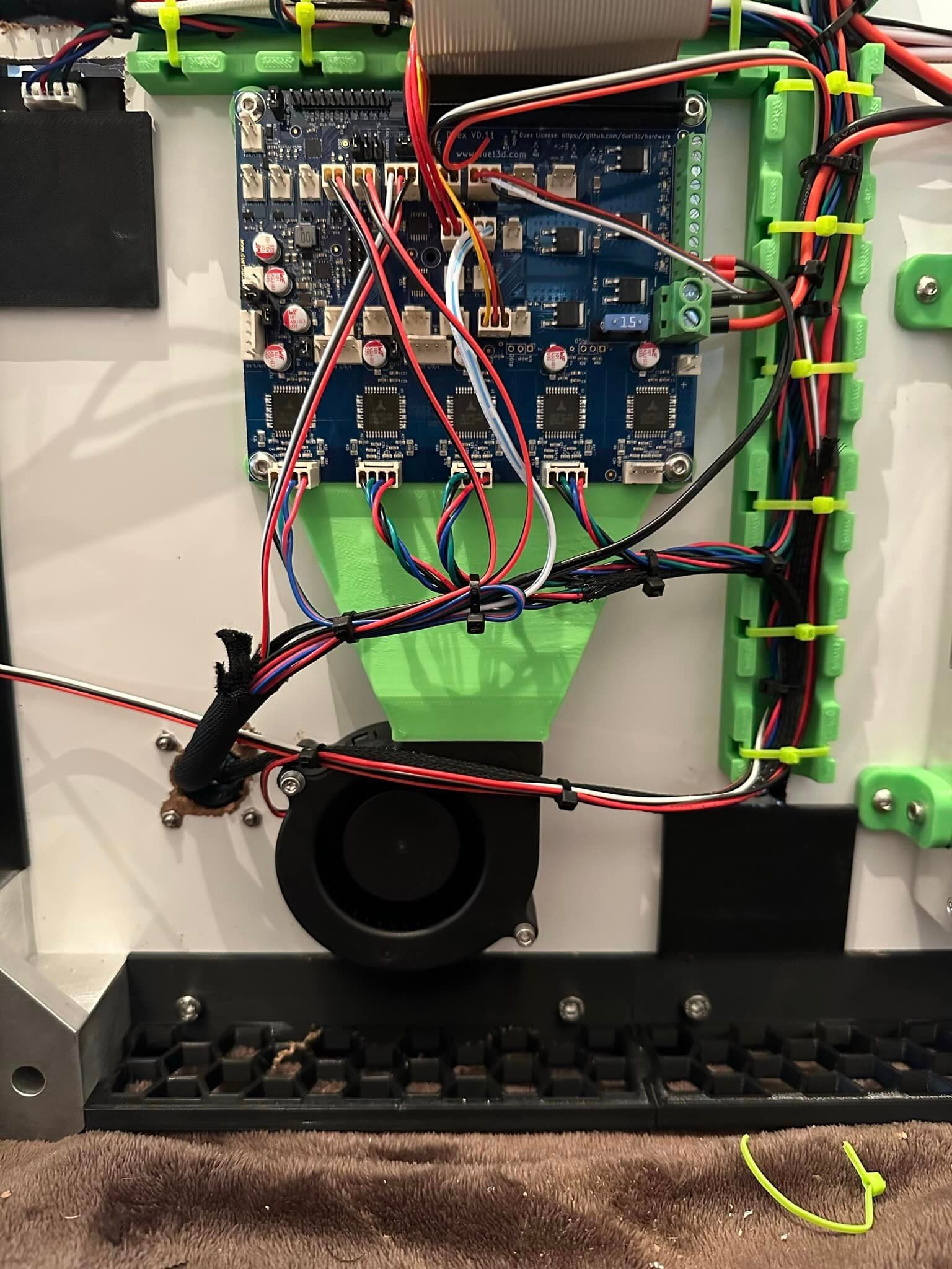
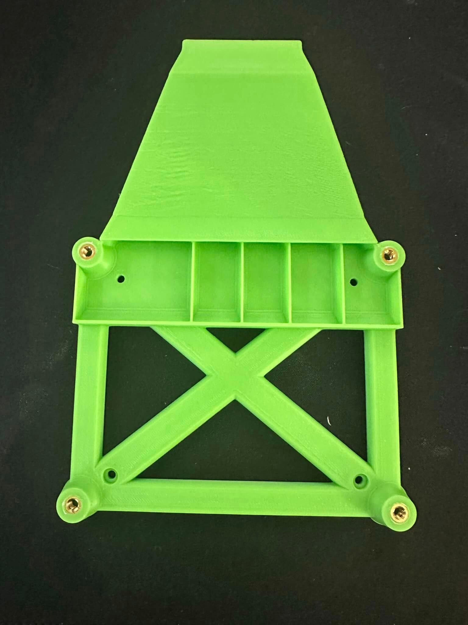
@Phaedrux Ok so my board is mounted horizontally with 10mm of air on the bottom side. I am going to raise that amount as much as I can and add a 24v blower wired to "Always on" that will blow across the bottom of the board on the drivers. Also, I turned down the current to 65%. I don't plan on speed printing with this printer so I will run some tests to see if that's enough. Based on your advice these items will resolve my issue. It will take some time to complete the hardware adjustments so for now I will consider this issue solved until I can run some additional tests. That is, unless you disagree?
-
RE: IDEX U Axis calibrationposted in General Discussion
@droftarts ; Tools
M563 P0 D0 H1 F0 ; define tool 0 that used low end X carriage
G10 P0 X0 Y0 Z0 ; set tool 0 axis offsets
G10 P0 R0 S0 ; set initial tool 0 active and standby temperatures to 0C
M563 P1 D1 H2 F2 X3 ; define tool 1 that used high end U carriage
G10 P1 X0 Y1.6 Z.34 ; set tool 1 axis offsets
G10 P1 R0 S0 ; set initial tool 1 active and standby temperatures to 0C -
RE: Standby Temperatureposted in General Discussion
@Phaedrux Yup that fixed it. So my M568 lines now read as:
M568 P0 S{first_layer_temperature[0]} R{first_layer_temperature[0] -15} A2 ; set E0 active/standby temp
M568 P1 S{first_layer_temperature[0]} R{first_layer_temperature[0] -15} A1 ; set E1 active/standby tempThank you for your help everyone. I'm still having other issues with my startup code but I will address those in another post. I don't want to flood this post. I consider this particular issue resolved.
Latest posts made by SonnyD1
-
RE: Railcore Upgrades/Updatesposted in General Discussion
@droftarts I may got with your recommendation of Tooboard. I didn't realize all of the advantages of the Roto TB. My chamber temps average around a max of 62c (with a bed temp of 110c). I'll have to do some testing to see what higher bed temps bring it up to to make sure I stay lower. I was going to add a PTC heater but now I suppose I shouldn't. I just have to devise a mount for the Roto board onto a Hemera XS. I'm sure that won't be too difficult. Thank you for the heads up! Any more advice or considerations?
-
RE: Shutdownsposted in General Discussion
@dc42 So that long print I was talking about shut down again in the middle of the night with nothing else running. Here is the M122: Thoughts?
M122 === Diagnostics === RepRapFirmware for Duet 2 WiFi/Ethernet version 3.6.0-rc.1 (2025-02-28 14:56:47) running on Duet WiFi 1.02 or later + DueX5v0.11 Board ID: 0JD0M-9P6B2-NJ4S4-6JKFJ-3SJ6Q-T82AK Used output buffers: 10 of 26 (24 max) === RTOS === Static ram: 24016 Dynamic ram: 68252 of which 0 recycled Never used RAM 30532, free system stack 156 words Tasks: NETWORK(1,ready,9.7%,222) HEAT(3,nWait 5,0.1%,328) Move(4,nWait 5,0.0%,288) DUEX(5,nWait 5,0.0%,23) MAIN(1,running,90.2%,734) IDLE(0,ready,0.0%,29), total 100.0% Owned mutexes: === Platform === Last reset 02:18:04 ago, cause: software Last software reset at 2025-03-11 06:24, reason: HardFault bfarValid precise, Gcodes spinning, available RAM 24264, slot 0 Software reset code 0x4063 HFSR 0x40000000 CFSR 0x00008200 ICSR 0x0041f803 BFAR 0xc9900000 SP 0x200022f8 Task MAIN Freestk 922 ok Stack: 80fe8000 43300000 00000000 407f4000 86600000 004601f3 0046262c 810e1a00 004084f3 00000000 00000064 004601f3 200023d3 00000001 00000001 00000000 00000066 0045c543 0000000a 00000000 41ec9c4c 20002418 00000000 40490000 0000000e 00000073 20002410 === Storage === Free file entries: 10 SD card 0 detected, interface speed: 20.0MBytes/sec SD card longest read time 3.3ms, write time 0.0ms, max retries 0 === Move === Segments created 2, maxWait 264ms, bed comp in use: none, height map offset 0.000, hiccups added 0/0 (0.00ms), max steps late 0, ebfmin 0.00, ebfmax 0.00 Pos req/act/dcf: 0.00/0/0.00 0.00/0/0.00 0.00/0/0.00 0.00/0/0.00 No step interrupt scheduled Driver 0: standstill, SG min n/a Driver 1: standstill, SG min n/a Driver 2: standstill, SG min n/a Driver 3: standstill, SG min 0 Driver 4: standstill, SG min n/a Driver 5: standstill, SG min n/a Driver 6: standstill, SG min n/a Driver 7: standstill, SG min n/a Driver 8: standstill, SG min n/a Driver 9: standstill, SG min n/a Driver 10: Driver 11: === DDARing 0 === Scheduled moves 1, completed 1, LaErrors 0, Underruns [0, 0, 0] Segments left 0 Code queue is empty === Heat === Bed heaters 0 -1 -1 -1, chamber heaters -1 -1 -1 -1, ordering errs 0 Heater 1 is on, I-accum = 0.0 === GCodes === Movement locks held by null HTTP is idle in state(s) 0 Telnet is idle in state(s) 0 File is idle in state(s) 0 USB is idle in state(s) 0 Aux is idle in state(s) 0 Trigger is idle in state(s) 0 Queue is idle in state(s) 0 LCD is idle in state(s) 0 Daemon is idle in state(s) 0 Autopause is idle in state(s) 0 === Filament sensors === Driver 11: ok === DueX === Read count 1, 0.01 reads/min === Network === Slowest loop: 10.20ms; fastest: 0.00ms Responder states: HTTP(0) HTTP(0) HTTP(0) FTP(0) Telnet(0) HTTP sessions: 1 of 8 === WiFi === Interface state: active Module is connected to access point Failed messages: pending 0, notrdy 0, noresp 0 Firmware version 2.2.1 Module reset reason: Power up, Vcc 3.38, flash size 2097152, free heap 39372 MAC address f4:cf:a2:68:3b:2f IP address 192.168.1.243 Signal strength -53dBm, channel 2, mode 802.11n, reconnections 0 Clock register 00002002 Socket states: 0 0 0 0 0 0 0 0 -
RE: Shutdownsposted in General Discussion
@dc42 That was the first check I made. Everything is snug with a good connection. I'm in the middle of a long print and the neighboring Railcore isn't running. No shutdowns yet. If is does point to only happening when a neighboring machine is running, how would I resolve that?
-
RE: Shutdownsposted in General Discussion
@Notepad Meanwell LRS-350-24. I don't buy cheap parts. I considered the possibility of a bad or faulty power supply because lets face it, it does happen. However, with this power supply it would be the least likely culprit I think. That said, I'm not opposed to replacing it since they are pretty affordable. I'd like to pursue other possibilities first.
-
RE: Shutdownsposted in General Discussion
@gloomyandy It was printing. Just an ordinary print. I'm beginning to see a pattern though. It only shuts down when its printing at the same time as the Railcore that's sitting right next to it is. Could be a coincidence but I don't think so.
-
Shutdownsposted in General Discussion
I have a printer that just recently started to randomly and seemingly for no reason , just shuts down. I ran a M122 afterwards.
M122
=== Diagnostics ===
RepRapFirmware for Duet 2 WiFi/Ethernet version 3.6.0-rc.1 (2025-02-28 14:56:47) running on Duet WiFi 1.02 or later + DueX5v0.11
Board ID: 0JD0M-9P6B2-NJ4S4-6JKFJ-3SJ6Q-T82AK
Used output buffers: 1 of 26 (18 max)
=== RTOS ===
Static ram: 24016
Dynamic ram: 68228 of which 0 recycled
Never used RAM 30556, free system stack 140 words
Tasks: NETWORK(1,ready,11.4%,222) HEAT(3,nWait 5,0.1%,328) Move(4,nWait 5,0.0%,270) DUEX(5,nWait 5,0.0%,23) MAIN(1,running,88.4%,734) IDLE(0,ready,0.1%,29), total 100.0%
Owned mutexes:
=== Platform ===
Last reset 00:12:48 ago, cause: software
Last software reset at 2025-03-08 21:47, reason: AssertionFailed, Platform spinning, available RAM 22784, slot 2
Software reset code 0x4920 HFSR 0x00000000 CFSR 0x00000000 ICSR 0x0041f823 BFAR 0xe000ed38 SP 0x2001ffac Task MAIN Freestk 31431 ok
Stack: 00002027 00476944 0045eb69 00000004 2000ba90 2000ca98 00000010 2000ca90 0045ade5 00000004 00000000 2000ca98 ffffffed 00000000 00f00000 e000e000 c0000000 20005d20 0045d2df 0045d054 21000000 ffffffff ffffffff ffffffff ffffffff ffffffff ffffffff
=== Storage ===
Free file entries: 10
SD card 0 detected, interface speed: 20.0MBytes/sec
SD card longest read time 3.4ms, write time 0.0ms, max retries 0
=== Move ===
Segments created 2, maxWait 268ms, bed comp in use: none, height map offset 0.000, hiccups added 0/0 (0.00ms), max steps late 0, ebfmin 0.00, ebfmax 0.00
Pos req/act/dcf: 0.00/0/0.00 0.00/0/0.00 0.00/0/0.00 0.00/0/0.00
No step interrupt scheduled
Driver 0: standstill, SG min n/a
Driver 1: standstill, SG min n/a
Driver 2: standstill, SG min n/a
Driver 3: standstill, SG min 0
Driver 4: standstill, SG min n/a
Driver 5: standstill, SG min n/a
Driver 6: standstill, SG min n/a
Driver 7: standstill, SG min n/a
Driver 8: standstill, SG min n/a
Driver 9: standstill, SG min n/a
Driver 10:
Driver 11:
=== DDARing 0 ===
Scheduled moves 1, completed 1, LaErrors 0, Underruns [0, 0, 0]
Segments left 0
Code queue is empty
=== Heat ===
Bed heaters 0 -1 -1 -1, chamber heaters -1 -1 -1 -1, ordering errs 0
Heater 1 is on, I-accum = 0.0
=== GCodes ===
Movement locks held by null
HTTP is idle in state(s) 0
Telnet is idle in state(s) 0
File is idle in state(s) 0
USB is idle in state(s) 0
Aux is idle in state(s) 0
Trigger is idle in state(s) 0
Queue is idle in state(s) 0
LCD is idle in state(s) 0
Daemon is idle in state(s) 0
Autopause is idle in state(s) 0
=== Filament sensors ===
Driver 11: ok
=== DueX ===
Read count 1, 0.08 reads/min
=== Network ===
Slowest loop: 8.34ms; fastest: 0.00ms
Responder states: HTTP(0) HTTP(0) HTTP(0) FTP(0) Telnet(0)
HTTP sessions: 1 of 8
=== WiFi ===
Interface state: active
Module is connected to access point
Failed messages: pending 0, notrdy 0, noresp 0
Firmware version 2.2.1
Module reset reason: Power up, Vcc 3.39, flash size 2097152, free heap 39372
MAC address f4:cf:a2:68:3b:2f
IP address 192.168.1.243
Signal strength -49dBm, channel 2, mode 802.11n, reconnections 0
Clock register 00002002
Socket states: 0 0 0 0 0 0 0 0
I have also had an error "Driver 7 Error: phase B short to ground" Anybody have an thoughts as to what may be going on?
Here is my config.g for reference.; Configuration file for Duet WiFi (firmware version 3.4.5) ; executed by the firmware on start-up ; ; generated by RepRapFirmware Configuration Tool v3.3.15 on Sun Feb 19 2023 17:01:06 GMT-0500 (Eastern Standard Time) ; General preferences G21 ; work in milimeters G90 ; send absolute coordinates... M83 ; ...but relative extruder moves M550 P"IDEX" ; set printer name M111 S0 ; debug off ; Network ;M552 S1 ; enable network M586 P0 S1 ; enable HTTP M586 P1 S1 ; enable FTP M586 P2 S0 ; disable Telnet M575 P1 B57600 S1 ; enable support for PanelDue ; Drives M569 P0 S1 ; physical drive 0 goes forwards - X stepper M569 P1 S1 ; physical drive 1 goes forwards - Z stepper (LEFT) M569 P2 S1 ; physical drive 2 goes forwards - Z stepper (RIGHT) M569 P3 S1 ; physical drive 3 goes forwards - E0 stepper M569 P6 S1 ; physical drive 6 goes forwards - Y stepper (LEFT) M569 P7 S0 ; physical drive 7 goes backwards - Y stepper (RIGHT) M569 P8 S1 ; physical drive 8 gows forwards - U stepper M569 P9 S1 ; physical drive 9 goes forwards - E1 stepper M584 X0 Y6:7 Z1:2 U8 E3:9 ; set drive mapping M350 X16 Y16 Z16 U16 E16:16 I1 ; configure microstepping with interpolation M92 X80.00 Y80.00 Z800.00 U80.00 E408.21:408.21 ; set steps per mm - ESTEPS M205 X20.00 Y18.00 Z1.00 U20.00 E5.00:5.00 ; set maximum instantaneous speed changes (mm/s^2) - JERK M203 X12000.00 Y12000.00 Z360.00 U12000.00 E3600.00:3600.00 ; set maximum speeds (mm/min) M201 X2000.00 Y2000.00 Z20.00 U2000.00 E250.00:250.00 ; set maximum ACCELERATIONS (mm/s^2) M204 P200 T2000 ; set print & travel ACCELERATIONS (mm/s^2) M906 X1400 Y1400 Z1400 U1400 E600:600 I30 ; set motor currents (mA) and motor idle factor in per cent M593 P"mzv" F60 S.7 ; set INPUT SHAPER M572 D0:1 S0.080 ; set PRESSURE ADVANCE for T0 & T1 M84 S30 ; Set idle timeout ; Axis Limits M208 X-26 Y0 U0 Z0 S1 ; set axis minima M208 X290 Y305 U360.47 Z300 S0 ; set axis maxima, If the (T1) U offset needs to move to the -X then the U axis limit will will increase ; Endstops M574 X1 S1 P"e1stop" ; configure switch-type (e.g. microswitch) endstop for low end on X via pin e1stop M574 U2 S1 P"duex.e6stop" ; configure switch-type (e.g. microswitch) endstop for high end on U via pin exp.e6stop M574 Y1 S1 P"duex.e5stop" ; configure switch-type (e.g. microswitch) endstop for low end on Y via pin exp.e5stop M574 Z1 S2 ; configure Z-probe endstop for low end on Z ;M591 D0 P1 C"xstop" S1 ; configure filament monitor (simple switch) for E0 ;M591 D1 P1 C"duex.e4stop" S0 ; configure filament monitor (simple switch) for E1 ; Emergency Stop M950 J1 C"e0stop" ; identify pin number for emergency stop M581 P1 T0 S1 R0 ; invoke trigger 0 when an inactive-to-active edge is detected on input 0 or input 3 and a file is being printed from SD card ; BLTouch M950 S0 C"duex.pwm1" ; create servo pin 0 for BLTouch M558 P9 C"^zprobe.in" H5 F120 T6000 ; set Z probe type to bltouch, connected to zprobe.in and the dive height + speeds G31 P500 X-31 Y-14.5 Z3.46 ; set Z probe trigger value, offset and trigger height. If you have to move the nozzle closer to the bed, increase the G31 Z value by the amount of baby stepping used. If you have to move the nozzle farther away from the bed, decrease the G31 Z value by the amount of baby stepping used. M557 X35:259 Y25:290 P5:5 ; define mesh grid M376 H10 ; taper off bed compensation over 10mm ; Heaters M308 S0 P"duex.e4temp" Y"thermistor" T100000 B3950 ; configure sensor 0 as thermistor on pin duex.e4temp M950 H0 C"bedheat" T0 ; create bed heater output on bedheat and map it to sensor 0 M307 H0 R0.901 K0.249:0.000 D1.86 E1.35 S1.00 B0 ; enable bang-bang mode for the bed heater and set PWM limit M140 H0 ; map heated bed to heater 0 M143 H0 S120 ; set temperature limit for heater 0 to 120C M308 S1 P"e0temp" Y"thermistor" T100000 B4725 C7.06e-8 ; configure sensor 1 as thermistor on pin e0temp M950 H1 C"e0heat" T1 ; create nozzle heater output on e0heat and map it to sensor 1 M307 H1 R4.899 K0.886:0.346 D1.80 E1.35 S1.00 B0 V24.0 ; disable bang-bang mode for heater and set PWM limit M143 H1 S300 ; set temperature limit for heater 1 to 300C M308 S2 P"duex.e3temp" Y"thermistor" T100000 B4725 C7.06e-8 ; configure sensor 2 as thermistor on pin duex.e3temp M950 H2 C"duex.e6heat" T2 ; create nozzle heater output on duex.e6heat and map it to sensor 2 M307 H2 R4.493 K0.675:0.344 D2.01 E1.35 S1.00 B0 V24.1 ; disable bang-bang mode for heater and set PWM limit M143 H2 S300 ; set temperature limit for heater 2 to 300C ; Fans M950 F0 C"fan2" Q500 ; create fan 0 on pin fan0 and set its frequency M106 P0 S0 H-1 ; set fan 0 value. Thermostatic control is turned off M950 F1 C"fan1" Q500 ; create fan 1 on pin fan1 and set its frequency M106 P1 S1 H1 T45 ; set fan 1 value. Thermostatic control is turned on at 45c M950 F2 C"duex.fan3" Q500 ; create fan 2 on pin duex.fan3 and set its frequency M106 P2 S0 H-1 ; set fan 2 value. Thermostatic control is turned off M950 F3 C"duex.fan4" Q500 ; create fan 3 on pin duex.fan4 and set its frequency M106 P3 S1 H2 T45 ; set fan 3 value. Thermostatic control is turned on at 45c ; Tools M563 P0 D0 H1 F0 ; define tool 0 that used low end X carriage G10 P0 X0 Y0 Z0 ; set tool 0 axis offsets G10 P0 R0 S0 ; set initial tool 0 active and standby temperatures to 0C M563 P1 D1 H2 F2 X3 ; define tool 1 that used high end U carriage G10 P1 X0 Y1.16 Z.13 ; set tool 1 axis offsets. If T1 needs to move in the -Y then the offset number will increase +Y G10 P1 R0 S0 ; set initial tool 1 active and standby temperatures to 0C ; Configure Accelerometer ;M955 P0 I50 C"spi.cs4+spi.cs3" ; Miscellaneous T0 ; select first tool M98 P"startwifi.g" -
RE: Railcore Upgrades/Updatesposted in General Discussion
@dc42 Do you think I should build a new config from scratch or just edit pins on this one?
-
RE: Railcore Upgrades/Updatesposted in General Discussion
@dc42 Here is my current config. I'm not opposed to changing the steppers if necessary. Currently running LDO 42STH40-1684MAC rated at 1.68A (XY & Z). The Hemera XS is rated at 1.4A. I would likely run that at 1000.
; Configuration file for SonnyD1 ; Communication and general M111 S0 ; Debug off M550 P"RailCore" ; Machine name and Netbios name (can be anything you like) ;*** Wifi Networking M552 S1 ; Enable WiFi M555 P2 ; Set output to look like Marlin M575 P1 B57600 S1 ; Comms parameters for PanelDue G21 ; Work in millimetres G90 ; Send absolute coordinates... M83 ; relative extruder moves ; Axis and motor configuration M669 K1 ; set CoreXY mode M584 X0 Y1 Z5:6:7 E3:4:8:9 ; Map Z to drivers 5, 6, 7. Define unused drivers 3,4,8 and 9 as extruders M569 P0 S0 ; Drive 0 goes forwards (change to S0 to reverse it) X stepper (Rear) M569 P1 S1 ; Drive 1 goes backwards Y Stepper (Front) M569 P2 S1 ; Drive 2 goes forwards Unused M569 P3 S0 ; Drive 3 goes forwards Extruder M569 P4 S1 ; Drive 4 goes forwards Extruder (unused) M569 P5 S0 ; Drive 5 goes backwards Front Left Z M569 P6 S0 ; Drive 6 goes backwards Rear Left Z M569 P7 S0 ; Drive 7 goes backwards Right Z ;Leadscrew locations M671 X-40:-40:383 Y22.5:277.5:150 S7.5 ;Front left, Rear Left, Right S7.5 is the max correction - measure your own offsets, to the bolt for the yoke of each leadscrew M350 X16 Y16 Z16 E16 I1 ; set 16x microstepping for axes & extruder, with interpolation M574 X1 S1 P"xstop" ; _RRF3_ set X endstop to xstop port active high M574 Y1 S1 P"ystop" ; _RRF3_ set Y endstop to ystop port active high M906 X1340 Y1340 Z1000 E1000 I50 ; Set motor currents (mA) M201 X3000 Y3000 Z100 E1500 ; Accelerations (mm/s^2) M203 X24000 Y24000 Z900 E3600 ; Maximum speeds (mm/min) M566 X1000 Y1000 Z100 E1500 ; Maximum jerk speeds mm/minute M208 X330 Y307 Z335 ; set axis maxima and high homing switch positions (adjust to suit your machine) M208 X0 Y0 Z-0.5 S1 ; set axis minima and low homing switch positions (adjust to make X=0 and Y=0 the edges of the bed) M92 X200 Y200 Z1600 E834.3 ; steps/mm M579 X1.0 Y1.0 Z1.0 ; scaling factor for Cartesian cords ; Thermistors M308 S0 P"bedtemp" Y"thermistor" A"Bed Heater" T100000 B3950 R4700 H0 L0 ;_RRF3_ Bed thermistor, connected to bedtemp on Duet2 M308 S1 P"e0temp" Y"thermistor" A"Extruder" T100000 B4725 R4700 C7.06e-8 H0 L0 ;_RRF3_ duet3 e3d M308 S2 P"duex.e3temp" Y"thermistor" A"Chamber" T10000 B3892 R4700 H0 L0 ;_RRF3_Chamber thermistor probe, connected to E3 Temp on duex ; Heaters M950 H0 C"BedHeat" T0 ;_RRF3_ define Bed heater is on bedheat M140 H0 ;__RRF3__ define bed heater (Required in 3.1 or later) M950 H1 C"e0heat" T1 ;_RRF3_ define Hotend heater is on e0heat M950 H2 C"duex.e3heat" T2 ;_RRF3_define Chamber heater is on e3heat M307 H0 B0 R0.345 C799.3 D21.12 S1.00 V24.1 ; Bed Heaters M307 H1 B0 R2.270 C194.3 D6.41 S1.00 V24.1 ; Heater 1 model M570 H1 S360 ; Hot end may be a little slow to heat up so allow it 180 seconds M143 S400 M143 H0 S140 ; Fans M950 F0 C"fan0" Q250 ; create fan 0 on pin fan0 and set its frequency M106 P0 S0 H-1 ; set fan 0 value. Thermostatic control is turned off M950 F1 C"fan1" Q250 ; create fan 1 on pin fan1 and set its frequency M106 P1 S1 H1 T45 ; set fan 1 value. Thermostatic control is turned on at 45c ; Tool definitions M563 P0 D0 H1 ; Define tool 0 M563 P2 S"Chamber" H2 G10 P0 S0 R0 ; Set tool 0 operating and standby temperatures G10 P2 S0 R0 ; Set Chamber display M558 P9 C"^zprobe.in" H5 R1 F100 T6000 A5 S0.02 ; _RRF3_ BLTouch connected to Z probe IN pin M950 S0 C"duex.pwm1" ; _RRF3_ Define BLTouch Servo (S0) on duet pwm1 G31 P25 X-4 Y42 Z2.55 ; Probe Trigger height/Z Offset and XY Offsets; If you have to move the nozzle closer to the bed, increase the G31 Z value by the amount of baby stepping used. If you have to move the nozzle farther away from the bed, decrease the G31 Z value by the amount of baby stepping used. M557 X25:300 Y25:285 P2:2 ; minimum and maximum coordinates to probe M501 T0 ; select first hot end -
Railcore Upgrades/Updatesposted in General Discussion
I have a Railcore ZL II with a Bondtech BMG, Mosquito, BLTouch running from a Duet2 and a Duex5. The umbilical is massive and I think it's about time to upgrade/update it to some newer technology. I'd like to add the nozzle swapping convenience of a Revo while still maintaining my high temp capabilities as well tool board benefits such as built in accelerometer and less wires. To that end, I am swapping to a Hemera XS w/ HT Revo hot side, Duet SZP running from a Duet 3 Mini 5 and a Duet 3 Tool Board 1LC v1.3. Im seeking feedback from the community. What are some things I may not have considered? How would you go about completing this upgrade/update? How much of my old config can I use? This is and has been my best printer for years. I don't want to make it worse, I want to make it better. Please, any and all feedback and thoughts are welcomed and appreciated.
