The Last Creality CR-Touch thread (how I got it to work)
-
Hi all,
I wanted to share my experience in connecting and configuring the Creality CR-Touch Z-Probe. There is some information here and there in various threads and the docs, but I felt a complete and comprehensive guide was missing (existing threads are help posts by users because they couldn't make it work, and then they just post "oh yeah I made it work" when someone asks and don't say how). I also want to provide some guidance since I destroyed my first CR-Touch due to switched wires which can be avoided. I thought it worth the effort to write up this little guide as the CR-Touch seems to be a more sturdy and precise alternative to the original BL-Touch probe.
(Disclaimer: this only applies to the CR-Touch Probe by Creality and their supplied cable connectors etc., I won't be responsible for any damage that might occur. My working setup is with the "Model AL T04" version of the CR-Touch, as printed on the probe)
There are some pointers in the docs as to the pinout. Notably there seem to have been different versions of the BL-Touch Z-Probe in a Creality version with varying pinout, but there is no explicit mention of the CR-Touch by Creality themselves. Maybe this can be added after this @T3P3Tony
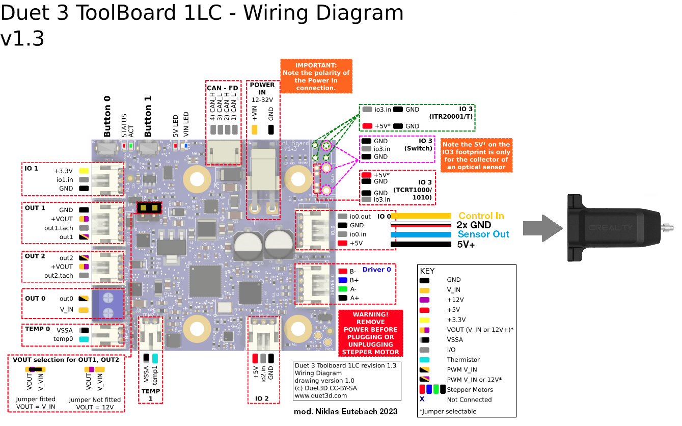
I've started out by measuring which cables would be the ground connection, since there seem to be two (one for the servo output, one for the sensor input). On the CR-Touch cable, the White and Red wire are the GND connections and can be combined into one crimp when pinning the connector (contrary to a user's statement in one of the aforementioned threads). As mentioned in the docs, Black is 5V+, Yellow is the servo control input, and Blue is the sensor output.
Important: don't mix the red and blue (GND and sensor output), since it will probably short out and destroy the measuring circuit for the optical sensor. In my case, this happened while the probe was still operable with M401/M402, but didn't put out any reading anymore. It also made the toolboard reset itself but luckily didn't damage it. I measured for continuity between the white and red cable to make sure these hold the same GND potential.
I wired the probe to the IO0 port of the 1LC Toolboard, I presume it must work the same if wired to the mainboard directly. I took the liberty to modify the 1LC wiring diagram to make it extra clear:
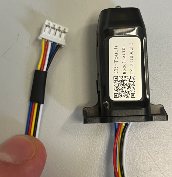
my shortened and pinned-for-duet connector cable:
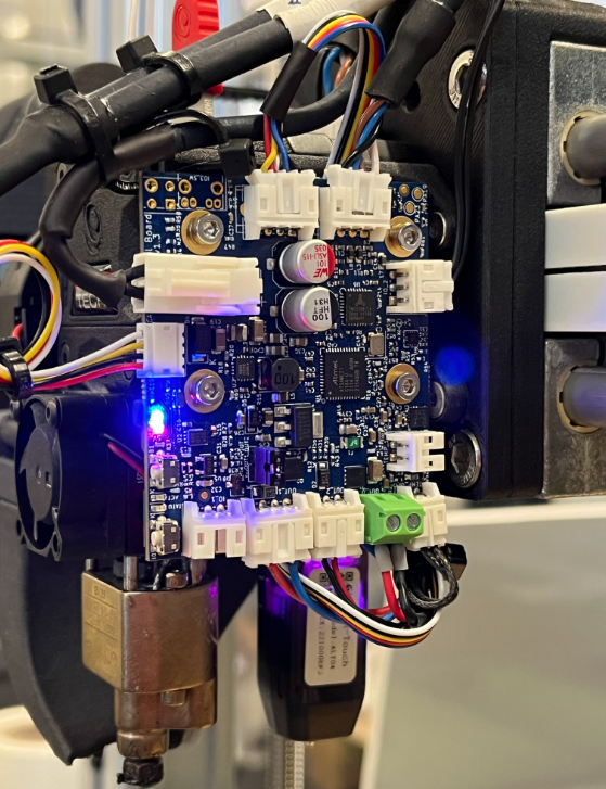
as installed on my print head:
As per the configuration, I did it like described in the docs:
from config.gM950 S0 C"121.io0.out" ; 121 is my toolboard CAN ID M558 P9 C"121.io0.in" H5 F120 T6000 G31 P500 X0 Y31 Z1.18 ; since the pin protrudes past the nozzle, the trigger height is positiveplus the deployprobe.g and retractprobe.g macros in the /sys folder.
from here on out, the deployment of the probe is like described for the BL-Touch in the docs.hope this will help one or two people that might find themselves in the position I was in two days ago.
best, Niklas
-
@sonderzug Thanks for your input, I'm glad you got it working. However, I think there are a couple of extra points that need to be made.
- The pinout of the BLTouch and CR Touch appear to be in the same order. I have found plenty of videos where they are swapped over by simply unplugging one and plugging in the other. Unfortunately, while I have a BLTouch, I don't have a CR Touch to test.
- What hasn't been consistent is the wiring colour/order Creality use. Your guide shows the way to wire the CR Touch with the wiring you were supplied with. Other users have experienced different wire colour orders. The Duet documentation reflects this.
- Creality sells both the BLTouch and the CR Touch. The CR Touch has a metal pin and uses an optical sensor (as I understand it) rather than the plastic pin and hall sensor used in the BLTouch (though BLTouch also produce a version with an optical sensor, just not as a 'consumer' product).
- Basically, it seems Creality, for some reason, flipped the cable in their kits. This makes a nonsense of the conventions of wire colour, as you found: Black (not red) is 5V, Red and white is GND. Thanks, Creality!
I have updated the Duet documentation here https://docs.duet3d.com/en/User_manual/Connecting_hardware/Z_probe_connecting#bltouch to mention the CR Touch by name, and to specify the pinout on both the BLTouch and the CR Touch from the orientation shown in the images. That way, users can test to find the ground pins on the probe pinout, rather than trust the colour of the wires.
Ian
Bed-slinger - Mini5+ WiFi/1LC | RRP Fisher v1 - D2 WiFi | Polargraph - D2 WiFi | TronXY X5S - 6HC/Roto | CNC router - 6HC | Tractus3D T1250 - D2 Eth
-
 undefined droftarts marked this topic as a question
-
undefined droftarts has marked this topic as solved
-
undefined droftarts moved this topic from Third-party add-ons
-
@droftarts Hi Ian, thanks for your remarks and for updating the documentation.
I was trying to make a point that I was in no way referring to the BL-Touch (clone) that Creality sells, but rather to "their own" product that is the CR-Touch. As far as I can tell, they have been consistent (however nonsensical) within the range of this specific product in terms of the wiring, e.g. my at least one year old, broken one that seems to have been version "AL T01" had the same wiring supplied as the one I bought last week, e.g. "AL T04". But yeah, it seems the safest way to ensure the order of the pinout is in fact to measure the both GND locations.
best, Niklas
-
@sonderzug, hello I might say, but I did install it today as substitute to my "plasticbottle" and I just unplugged it and replugged it and it works... no changes in config, no wire issues. Swapout and continue working.
Just wanted to note that if somebody swaps a BL-Touch for Creality CR-Touch.
All the best.
-
@sonderzug Hi I have the same cr touch and LC board, wiring is correct but it shows Error: "G30: Probe was not triggered during probing move." Can you send me full configuration?