Connection 4 tools in mainboard
-
Hallo,
ich verwende 4 Druckköpfe mit vier verschiedenen Tool Boards 1LC.
Meine Mainboard ist das Duet3d 6HC.
Leider kann ich nur drei Druckköpfe definieren.
Zumindest sehe ich nur drei die ich auch steuern kann.
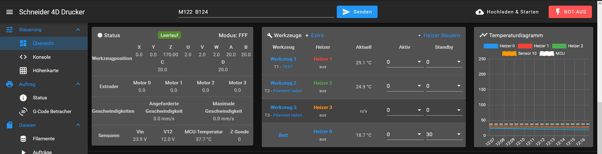
Hier meine Config; Configuration file for Duet 3 MB 6HC (firmware version 3.3) ; executed by the firmware on start-up ; ; generated by RepRapFirmware Configuration Tool v3.3.15 on Fri Mar 03 2023 12:36:13 GMT+0100 (Mitteleuropäische Normalzeit) ; General preferences M575 P1 S1 B57600 ; enable support for PanelDue G90 ; send absolute coordinates... M83 ; ...but relative extruder moves M550 P"Schneider" ; set printer name M669 K1 ; select CoreXY mode ; Wait a moment for the CAN expansion boards to start G4 S2 ; Network M551 P"Schneider" ; set password M552 P192.168.1.14 S1 ; enable network and set IP address M553 P255.255.255.0 ; set netmask M554 P192.168.1.254 ; set gateway M586 P0 S1 ; enable HTTP M586 P1 S1 ; enable FTP M586 P2 S0 ; disable Telnet ; Drives M569 P0.0 S0 ;X - Achse ; physical drive 0.0 goes backwards M569 P0.1 S0 ;Y - Achse ; physical drive 0.1 goes backwards M569 P0.2 S0 ;Z - Achse 1 ; physical drive 0.2 goes backwards M569 P0.3 S0 ;Z - Achse 2 ; physical drive 0.3 goes backwards M569 P0.4 S1 ;Flies Spanner 1 ; physical drive 0.4 goes forwards M569 P0.5 S1 ;Flies Spanner 2 ; physical drive 0.5 goes forwards M569 P1.0 S1 ;Flies Spanner 3 ; physical drive 1.0 goes forwards M569 P1.1 S1 ;Flies Spanner 4 ; physical drive 1.1 goes forwards M569 P1.2 S0 ;Kabelzug 1 ; physical drive 1.2 goes forwards M569 P2.0 S0 ;Kabelzug 2 ; physical drive 2.0 goes forwards M569 P2.1 S0 ;Kabelzug 3 ; physical drive 2.1 goes forwards M569 P2.2 S0 ;Kabelzug 4 ; physical drive 2.2 goes forwards M569 P121.0 S0 ; physical drive 121.0 goes forwards M569 P122.0 S0 ; physical drive 122.0 goes forwards M569 P123.0 S0 ; physical drive 123.0 goes forwards M569 P124.0 S1 ; physical drive 124.0 goes forwards M584 X0.0 Y0.1 Z0.2:0.3 A0.4 B0.5 C1.0 D1.1 U1.2 V2.0 W2.1 i2.1 E121.0:122.0:123.0:124.0 ; set drive mapping M350 X32 Y32 Z4:4 A16 B16 C16 D16 U16 V16 W16 i16 E16:16:16:16 I1 ; configure microstepping with interpolation M92 X80.00 Y80.00 Z160.00:160.00 A400.0 B400.0 C400.0 D400.0 U80.0 V80.0 W80.0 i80.0 E100.00:100.00:100.00:100.00 ; set steps per mm M566 X900.00 Y900.00 Z160.00:160.00 A120.0 B120.0 C120.0 D120.00 U120.0 V120.0 W120.0 i120.0 E120.0:120.00:120.00:120.00 ; set maximum instantaneous speed changes (mm/min) M203 X6000.00 Y6000.00 Z280.00:280.0 A180.0 B180.0 C180.0 D180.0 U180.0 V180.0 W180.0 i180.0 E1200.00:1200.00:1200.00:1200.00 ; set maximum speeds (mm/min) M201 X500.00 Y500.00 Z200.00:200.00 A20.00 B20.0 C20.0 D250.00 U20.0 V20.0 W20.0 i20.0 E250.0:250.00:250.00:250.00 ; set accelerations (mm/s^2) M906 X800 Y800 Z800:800 A800 B800 C800 D800 U800 V800 W800 i800 E800:800:800:800 I90 ; set motor currents (mA) and motor idle factor in per cent M84 S30 ; Set idle timeout ; Axis Limits M208 X0 Y0 Z0 U0 V0 W0 A0 B0 C0 D0 S1 ; set axis minima M208 X850 Y850 Z400 U300 V30 W300 A300 B300 C300 D300 S0 ; set axis maxima ; Endstops M574 X1 S1 P"io1.in" ; configure switch-type (e.g. microswitch) endstop for low end on X via pin io2.in M574 Y1 S1 P"io2.in" ; configure switch-type (e.g. microswitch) endstop for low end on Y via pin io1.in M574 Z1 S3 ;P"123.io0.in" ; configure switch-type (e.g. microswitch) endstop for low end on Z via pin io4.in M574 U1 S1 P"1.io4.in" M574 V1 S1 P"1.io5.in" M574 W1 S1 P"2.io0.in" M574 i1 S1 P"2.io1.in" M574 A1 S1 P"io5.in+io6.in" M574 B1 S1 P"io7.in+io8.in" M574 C1 S1 P"1.io0.in" M574 D1 S1 P"1.io2.in" ; Z-Probe M950 S18 C"121.io0.out" M558 P9 C"121.io0.in" H10 F20 T6000 ; disable Z probe but set dive height, probe speed and travel speed G31 P500 X0 Y0 Z1 M557 X15:200 Y15:195 S20 ; define mesh grid ; Heaters T:1000.0 B:3950.0 C:7.06e-8 R:2200.0 L:127 H:127 ;T:1000.0 B:3950.0 C:7.06e-8 R:2200.0 L:0 H:-17 M308 S0 P"temp1" Y"thermistor" T50000 M950 H0 C"out0" Q10 T0 ; create bed heater output on out0 and map it to sensor 0 M307 H0 R1.1 D30000 B0 S1.0 ; enable bang-bang mode for the bed heater and set PWM limit M140 H0 R30 ; map heated bed to heater 0 M143 H0 S100 ; set temperature limit for heater 0 to 200C M308 S10 P"temp0" Y"PT1000" T1000 B3950 ; configure sensor 10 as thermistor on pin temp0 M308 S1 P"121.temp0" Y"thermistor" T100000 ; configure sensor 1 as PT1000 on pin 121.temp0 M950 H1 C"121.out0" T1 ; create nozzle heater output on 121.out0 and map it to sensor 1 M307 H1 B0 S1.0 ; enable bang-bang mode for the bed heater and set PWM limit M143 H1 S250 ; set temperature limit for heater 0 to 200C M308 S2 P"122.temp0" Y"thermistor" T100000 M950 H2 C"122.out0" T2 M307 H2 B0 S1.0 M143 H2 S250 M308 S3 P"123.temp0" Y"termistor" T100000 M950 H3 C"123.out0" T3 M307 H3 B0 S1.0 M143 H3 S250 M308 S4 P"124.temp0" Y"termistor" T100000 M950 H4 C"124.out0" T4 M307 H4 B0 S1.0 M143 H4 S250 ; Fans M308 S15 Y"mcu-temp" A"MCU" M950 F15 C"!out4" Q500 ;CPU Lüfter ; create fan 0 on pin !out4 and set its frequency M106 P15 S10 T30 H15 C"CPU Lüfter Mainboard" ; set fan 0 value. Thermostatic control is turned off M950 F16 C"2.out3" Q500 ; create fan 1 on pin !2.out3 and set its frequency M106 P16 S100 T30 H15 C"Board Lüfter" ; set fan 1 value. Thermostatic control is turned off M950 F1 C"121.out1" Q250 M106 P0 S1 H1 M950 F2 C"122.out1" Q250 M106 P0 S10 H2 M950 F3 C"123.out1" Q250 M106 P0 S10 H3 M950 F4 C"124.out1" Q250 M106 P0 S10 H4 M950 F5 C"121.out2" Q250 M106 P0 S10 H5 M950 F6 C"122.out2" Q500 M106 P0 S10 H6 M950 F7 C"123.out2" Q500 M106 P0 S10 H7 M950 F8 C"124.out2" Q500 M106 P0 S10 H8 ; Tools M563 P1 D1 H1 F1 ; define tool 0 G10 P1 X0 Y0 Z0 ; set tool 0 axis offsets G10 P1 R0 S0 M563 P2 D2 H2 F2 G10 P2 X0 Y0 Z0 G10 P2 R0 S0 M563 P3 D3 H3 F3 G10 P3 X0 Y0 Z0 G10 P3 R0 S0 M563 P4 D4 H4 F4 G10 P4 X0 Y0 Z0 G10 P4 R0 S0 M563 P5 D5 H5 F5 G10 P5 X0 Y0 Z0 G10 P5 R0 S0 ; set initial tool 0 active and standby temperatures to 0C ; Custom settings are not defined M950 P11 C"!Out1" M42 P11 S0 ;Alle Achsen Freigen ohne Referenzfahrt M564 H0 S1 ;Achsen Freigen G4 S1 ;Wartezeit 1 Sekunden G91 G1 Z15 ;Z - Achse 15mm nach oben fahren G92 M564 H1 S1 ;Freigabe zurük nehemen ; Miscellaneous M501 ; load saved parameters from non-volatile memory M911 S10 R11 P"M913 X0 Y0 G91 M83 G1 Z3 E-5 F1000" ; set voltage thresholds and actions to run on power lossHier das Web Interface.
Kann mir da Jemand Helfen?
Wie bekommen ich das fehlende 4 Tool angezeigt?
Oder sind da grenzen gesetzt?
Wo liegt der Fehler?Hello,
I am using 4 print heads with four different tool boards 1LC.
My mainboard is the Duet3d 6HC.
Unfortunately I can only define three printheads.
At least I only see three that I can control.Here is the web interface.
Can someone help me?
How do I get the missing 4 tool displayed?
Or are there limits?
Where is the error? -
@UserXY said in Connection 4 tools in mainboard:
M350 X32 Y32 Z4:4 A16 B16 C16 D16 U16 V16 W16 i16 E16:16:16:16 I1 ; configure microstepping with interpolation
M92 X80.00 Y80.00 Z160.00:160.00 A400.0 B400.0 C400.0 D400.0 U80.0 V80.0 W80.0 i80.0 E100.00:100.00:100.00:100.00 ; set steps per mm
M566 X900.00 Y900.00 Z160.00:160.00 A120.0 B120.0 C120.0 D120.00 U120.0 V120.0 W120.0 i120.0 E120.0:120.00:120.00:120.00 ; set maximum instantaneous speed changes (mm/min)
M203 X6000.00 Y6000.00 Z280.00:280.0 A180.0 B180.0 C180.0 D180.0 U180.0 V180.0 W180.0 i180.0 E1200.00:1200.00:1200.00:1200.00 ; set maximum speeds (mm/min)
M201 X500.00 Y500.00 Z200.00:200.00 A20.00 B20.0 C20.0 D250.00 U20.0 V20.0 W20.0 i20.0 E250.0:250.00:250.00:250.00 ; set accelerations (mm/s^2)
M906 X800 Y800 Z800:800 A800 B800 C800 D800 U800 V800 W800 i800 E800:800:800:800 I90for starters, you should only have 1 set of Z values.
@UserXY said in Connection 4 tools in mainboard:
M584 X0.0 Y0.1 Z0.2:0.3 A0.4 B0.5 C1.0 D1.1 U1.2 V2.0 W2.1 i2.1 E121.0:122.0:123.0:124.0
you have 4 extruders mapped but your M563 lines start at
D1rather thanD0.Best run
M98 P"config.g"and see what errors get reported -
@jay_s_uk said in Connection 4 tools in mainboard:
M563-
He,

vielen Dank ja das war mein Fehler den ich Langezeit gesucht habe.Vielen Dank
-
 undefined jay_s_uk marked this topic as a question
-
undefined jay_s_uk has marked this topic as solved
-
Könntest du mir noch bei dem Problem mit dem Temperatur Fühler helfen?
Ich bekomme keine Messwerte bei beiden tool boards.
Ich habe ein 103000 Ohmen gemessen bei Raumtemperatur es sind auch 100.000
Ohmen Sensoren verbaut.Weißt du ein Rat wieso ich keine Messwerte er halte?
Oder sind die tool borads kaputt?
-
@UserXY your config looks correct. did you run
M98 P"config.g"?
please post an output from that.
Also, a photo of your wiring on one of the boards would be good -
Hallo,
ich habe den Fehler gefunden.
Es hat sich ein tipp Fehler eingeschlichen.
Ich habe das "h" bei Thermistor nicht geschrieben.
@UserXY said in Connection 4 tools in mainboard:
M308 S2 P"122.temp0" Y"thermistor" T100000
M950 H2 C"122.out0" T2
M307 H2 B0 S1.0
M143 H2 S250M308 S3 P"123.temp0" Y"termistor" T100000
M950 H3 C"123.out0" T3
M307 H3 B0 S1.0
M143 H3 S250Nun habe ich es verbessert und siehe da es Funktioniert perfekt.
Vielen Dank für deine Hilfe.
-
@UserXY great