Duet 3 board for Servo Build - Need 3.3v Step/Dir
-
I'm working on design of a new printer that will use a pair of Yaskawa servos (SGM7A-02A) for XY motion. I already have the servos, so I'm trying to match to them. Z-axis will be driven by three steppers.
I also already have a Duet 3 6HC, which my initial thought was to re-use with a pair of 1XD expansions. Then I found this in the driver specs for the Yaskawas:
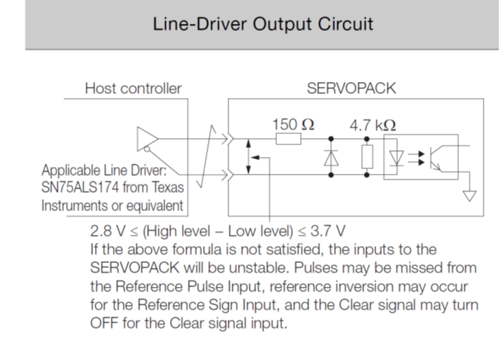
I interpret that as basically saying it wants 3.3V inputs. Please correct me already at this point if I'm overlooking something.
If I want to stick with a Duet 3 6HC or 6XD, this seems to be a problem, as the 6XD and 1XD both have 5V signaling. But, if my math is right--and it often isn't--putting 100ohm resistors on DO_Step(-) and DO_Dir(-) would correct for the voltage range. Using 1XDs in differential mode, you could put the resistors on either lead (+/-), but for the 6XD or for the 1XD single-ended, they'd have to go on individual DO_Step(-) and DO_Dir(-) specifically, and not on +5V. Right?
If that works, it raises the next concern; would adding these resistors adversely effect rise/fall times? The drivers want ≤ 0.025μs rise/fall on step/dir signals (and max M569 T0.125:0.25:0.5:0.5, if that makes any difference).
If there's no issue with the above fix, is there any strong reason to go one route versus the other, meaning 6HC+1XDs versus 6XD? I have noted that the step rate for the 6XD is quite a bit higher than the 1XD, but I haven't yet gotten around to mathing-out the practical implications of that. I would be happy for any arguments to go one way or the other.
Thanks all!
-
@Maestro see https://docs.duet3d.com/en/User_manual/Connecting_hardware/Motors_servos
Connect the PWM wire to an appropriate PWM pin on the Duet. Most 5V servos seem to work fine with the 3.3V signalling most Duet I/O pins supply.
Duet 3 Mainboard 6HC: There is a dedicated 5V PWM header, which provides 5V signalling, shared with OUT_9. Otherwise use any PWM-capable IO[n].out pin for 3.3V signalling. See Duet 3 MB6HC Hardware Overview. Headers on CAN-connected expansion boards can also be used.Ian
Bed-slinger - Mini5+ WiFi/1LC | RRP Fisher v1 - D2 WiFi | Polargraph - D2 WiFi | TronXY X5S - 6HC/Roto | CNC router - 6HC | Tractus3D T1250 - D2 Eth
-
@droftarts, the Connecting External Stepper and Servo Motor Drivers page makes no mention of using IO PWM for motion control, and says that "The Duet 3 Mainboard 6HC has no on-board external driver pins. Use a CAN bus connected expansion board to provide signaling for the external driver", which makes me wonder if there aren't limitations to using IO pins for motor control?
What the max stepping rate through an IO port? Isn't the max PWM something like 60kHz, which would be well below "fast" timing speeds? What GCode is used to redirect step/dir outputs to the IO ports rather than motor drivers?
Even if there are no other limitations, this would use up at least 5 IO ports to run 2 servos, which is far from ideal. I would still like to know if a simple resistor on the dedicated driver outputs would solve the problem.
-
@Maestro sorry, my mistake. I read your first message too quickly and thought you were trying to connect hobby servos to your Duet, not servo drives!
You are correct, the 6HC does not have provision to drive external drivers for stepper or servo motors. You will need CAN connected 1XD boards, or swap to a 6XD (you’ll need external drivers, or a 3HC to drive the Z steppers then). I’m not sure about reducing the signal voltage on the 1XD/6XD; @dc42 would be the best person to respond on that. It’s a bit odd that a large servo drive requires a 3.3V input, not 5V.
Another option, if they do need 3.3V, is to wire the 1XD and 6XD in single ended mode, but use a 3.3V pin instead of 5V.
Ian
Bed-slinger - Mini5+ WiFi/1LC | RRP Fisher v1 - D2 WiFi | Polargraph - D2 WiFi | TronXY X5S - 6HC/Roto | CNC router - 6HC | Tractus3D T1250 - D2 Eth
-
@droftarts Yeah, I was caught off-guard a bit when I came across the above figure, as I was just assuming it would be 5V. To make matters worse, the position reference inputs are Pulse, Direction, and Clear, not Pulse, Direction, and Enable. To turn the servos on, the drives require a separate, 24V input. So, talking with these drives is proving more involved than I hoped. But, they have 24-bit optical encoders, so, you win some, you lose some...
You make a good point to run single-ended pulling from a 3.3V pin instead of the 5V, and I have to admit that didn't even occur to me, but it seems like a reliable fallback. I do still like the resistor approach if it works though, just because it keeps all the connections physically discreet.
Come to think of it, though, any chance the EN(-) pins on the 6XD are 30V tolerant so I could actually use them for enable/on signal?