Common lines for compact wiring - PCB design
-
Dear Forum,
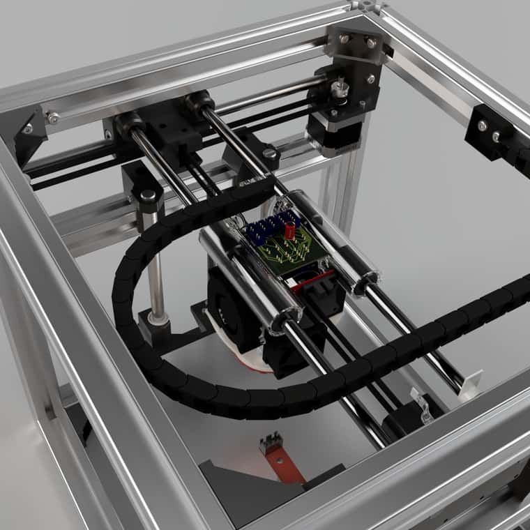
I am rewiring my printer as I am switching to a new carriage and cable chain.
My plan is to get rid of as many cables as possible.This post is a continuation of my old thread from https://forum.duet3d.com/topic/32939/common-lines-for-compact-wiring
Consolidated Wiring Plan for Printer Carriage:
- Common lines:
- 24V, GND, 5V
- Fans:
- Common 24V
- Only negative connectors go to the board (PWM Modulated)
- Heater Cartridge:
- Common 24V
- PWM Modulated negative
- LED Lighting: Utilize a common GND and 5V lines
- Optical Endstop: Utilize common GND, 5V, and one data line.
- BLTouch (BLT):
- Wiring similar to Optical Endstop.
- Both GND pins bridged?
- @dc42 said transient current might cause false triggering; potentially mitigate with a decoupling capacitor between 5V and GND at the tool head. Which capacitor size is recommended?
- Thermistors: Cannot use a common ground due to Duet's separation of analog and digital grounds.
PCB Design:
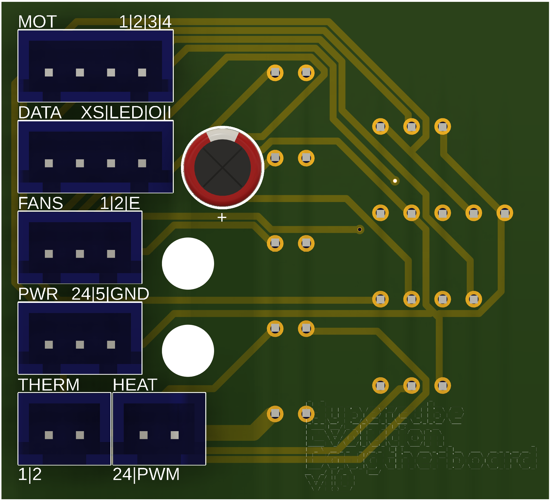
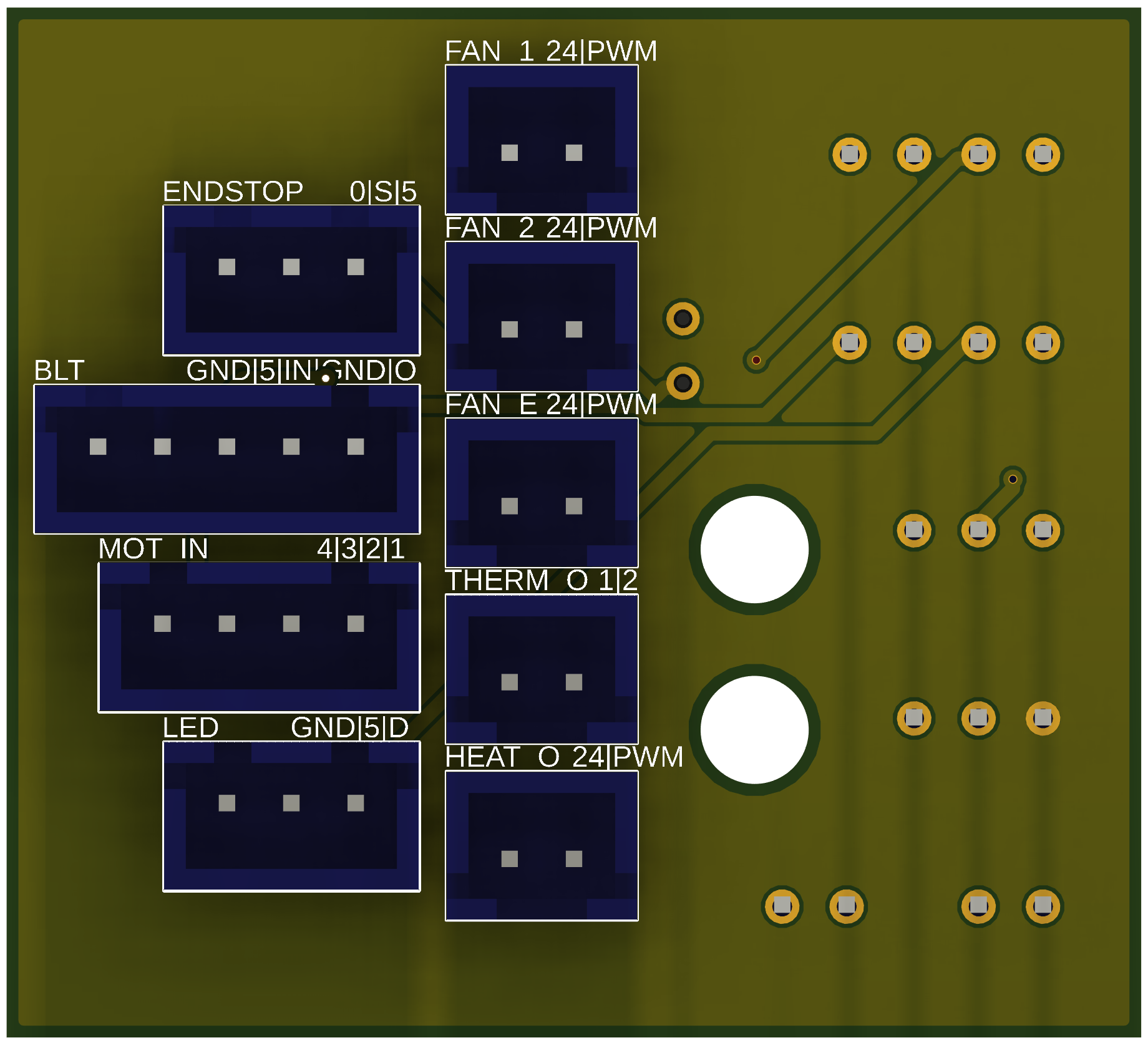
I came up with the following PCB. As it is my first one, there could well be some flaws or thigs I missed.
It would be great if someone could look at it and share their opinion.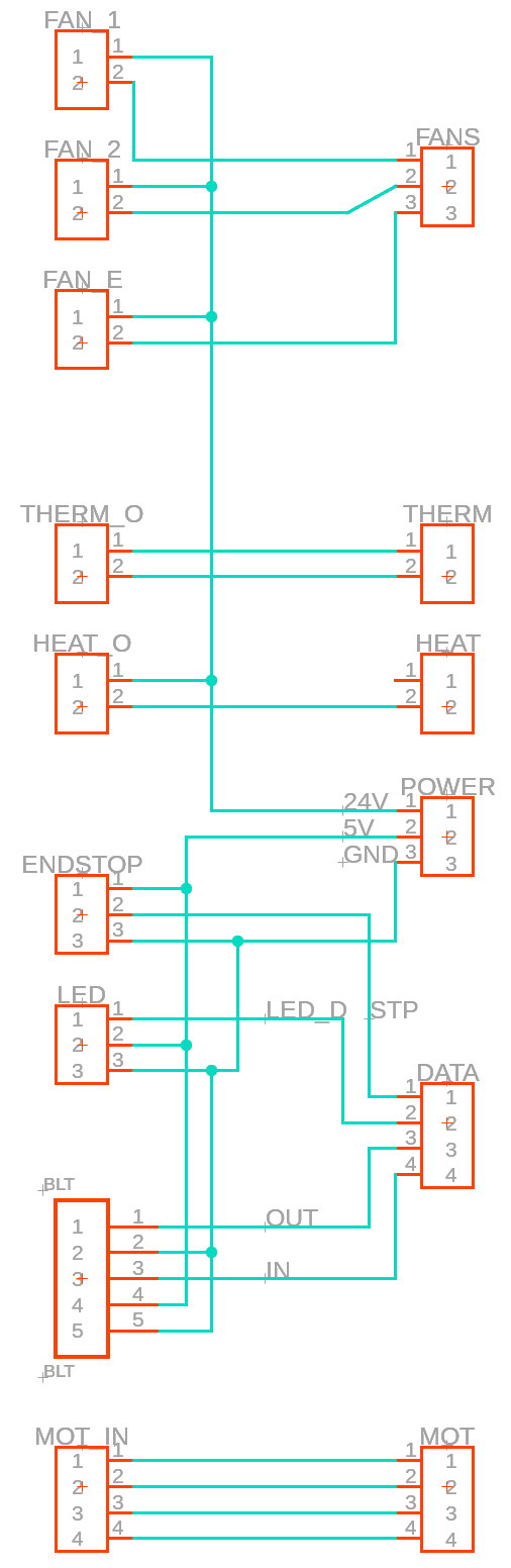
Left is the input side coming from the carriage, and right the reduced wires going to the Duet Wifi
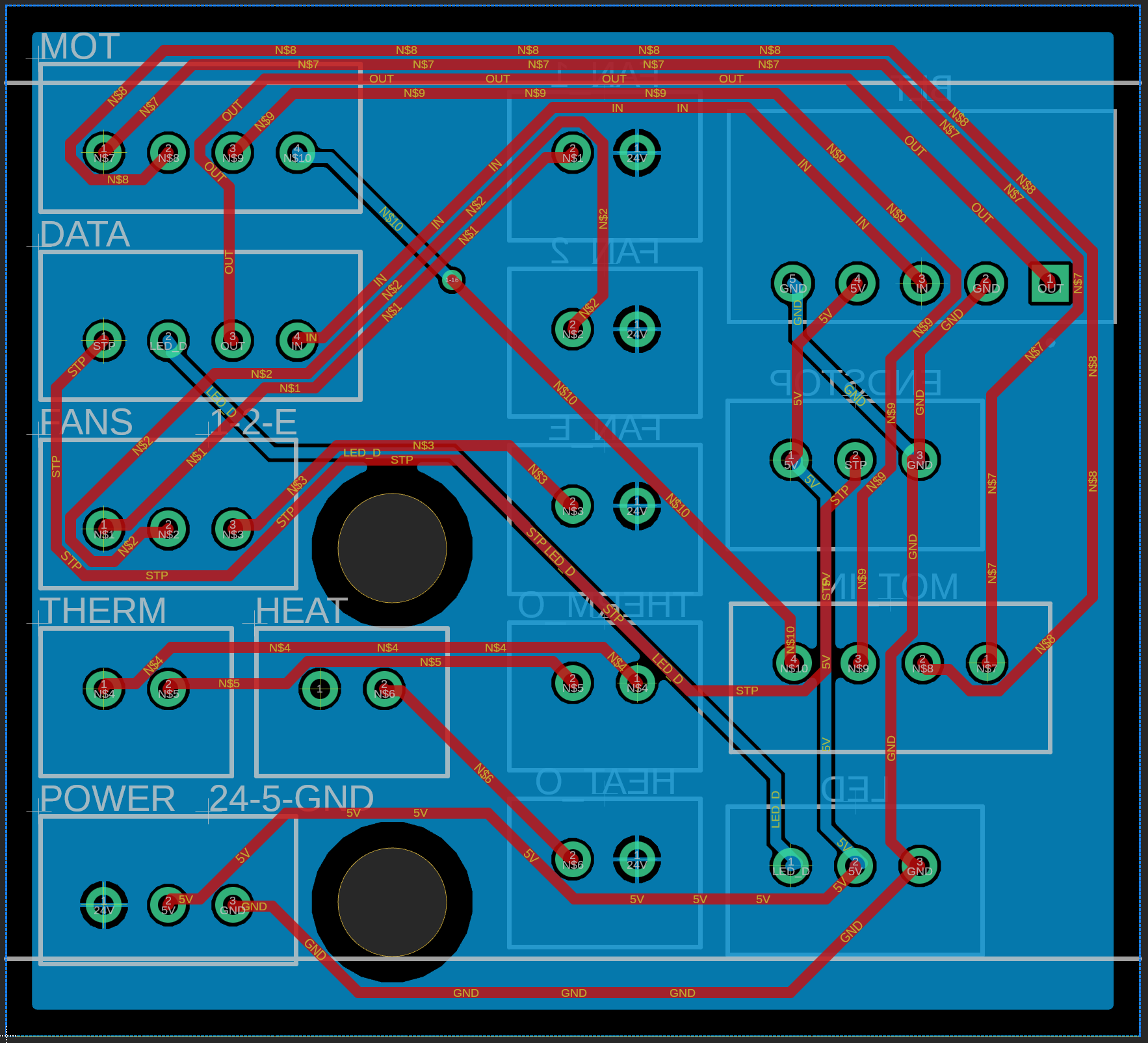
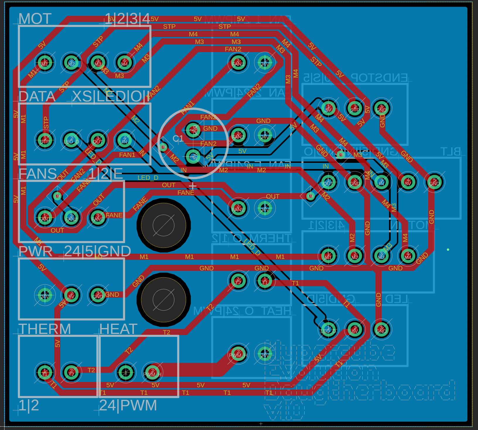
This is the actual PCB layout. I created a 24V plane, as i though this is the line carrying most of the current.
Are the connectors sized adequately? Is there any issue/danger in the design?Note:
So far I am missing the fuse and the coupling capacitor. - Common lines:
-
This post is deleted! -
@Tryptamine Your heater ground is carrying nearly as much current as your 24V plane, as the majority of the current draw will be from the heater. The heater ground paths need to be sized for that.
-
-
@Tryptamine Everything looks sorted to me. If the DRC check is clean I'd think you're set to go.
-
@Maestro
Thanks for the feedback!Things I am still unsure about:
- the BLT has GND twice. Is it sufficient to wire only one ground to some ground of the Duet, or does the ground have to be connected twice?
- How to dimension the smoothing capacitor between 5v and GND?
- Is the 50 mils connection for the heater PWM large enough?
- Should I fuse the 24V on the board?
-
@Tryptamine said in Common lines for compact wiring - PCB design:
Things I am still unsure about:
- the BLT has GND twice. Is it sufficient to wire only one ground to some ground of the Duet, or does the ground have to be connected twice?
One ground wire should suffice.
- How to dimension the smoothing capacitor between 5v and GND?
I suggest 100uF.
- Is the 50 mils connection for the heater PWM large enough?
Use e.g. https://www.4pcb.com/trace-width-calculator.html to check.
- Should I fuse the 24V on the board?
Not necessary if the VIN fuse on the Duet provides sufficient protection and you take the 24V wire from the fused supply on the Duet, e.g. from the heater output connector (assuming that connector has a high enough rating for the total 24V current). If you take it directly from the 24V PSU then you should fuse it.