Connect a Mellow Fly RRF-36 to a Duet Tool Distribution Board?
-
@weed2all said in Connect a Mellow Fly RRF-36 to a Duet Tool Distribution Board?:
@edsped you only need to use the 2 pins without * markings...those that are market with * are passed directly from IN and OUT CAN ports!
I hope to use 4 RRF-36's on a toolchanger so would run the 2 CAN wires from the RRF-36's to the Tool Distribution Board by connecting pins (1) and (2) on tool 0, (1) and (2) on tool 1, (1) and (2) on tool 2 and (1) and (2) on tool 3. With all jumpers removed? I guess what I'm not getting is that the Duet CAN board uses (4) CAN wires and (2) power while the RRF uses (2) CAN wires and (2) power.
-
@edsped I could be wrong but IIRC, Duet main boards have 4 can conductors (2 pairs) but only 2 conductors are actually used (1 pair).
-
@edsped Didn't you ask the same question over on the RRF Discord? I posted an answer over there:
There are two issues that you need to deal with...
- The Duet toolboards have 4 CAN wires going to them, the RRF36 only has two.
- What to do about termination.
With a Duet board the CAN bus in effect is looped out to each toolboard (with one set of wires going out and one returning), but with the RRF36 boards you can't really do this. So the alternative is rather than looping the bus out and back to each board, you in effect have the entire can "bus" on the distribution board and use a "drop cable" or spur connection to the toolboards. This only requires 2 wires to each toolboard. Although this way of wiring things is not as robust as looping the bus out and back it should be fine for the sort of cable runs used in a typical printer. The maximum length of the drop cables should be limited to a maximum of 1m (ideally less). So to configure this, you would install all of the bypass jumpers on the distribution board and then connect the two CAN wires from the RRF36 to pins 1 and 2 of each socket, leave pins 3 and 4 disconnected.
From the main control board you should connect the CAN signals from the control board to pins 3 and 4 on the distribution board.
Next you need to deal with the termination resistors. Basically you need a termination at each end of the bus, so for any CAN bus you should only have a maximum of 2 termination resistors in place. Usually the control board will come with one terminator already connected, so we just need to add one more at the "other end" of the bus. There are two possible locations that can be used as the end of the bus in the configuration I described above. The first is to use the terminator built into the distribution board, the second is to enable the terminator on the "last" RRF36 board. I'd recommend using the one on the distribution board.
Did you try the setup I suggested?
-
Yes that was me but I opted to post here as Discord is a little difficult to keep track of discussions I have not tried anything yet, the remaining 3 RRF36 boards arrived yesterday and I'm ready to start wiring and bench testing this. The printer is with the exception of WiFi issues, printing happily on a Duet 2 setup now and I'm hoping to have enough of a handle on how to attack this that it's just a matter of rewiring and firing it up with minimal issues. For some reason I'm struggling with how the CAN setup works.
-
This post is deleted! -
@Herve_Smith thanks for keeping the discussion on target
Owns various duet boards and is the main wiki maintainer for the Teamgloomy LPC/STM32 port of RRF. Assume I'm running whatever the latest beta/stable build is
-
@gloomyandy said in Connect a Mellow Fly RRF-36 to a Duet Tool Distribution Board?:….
Sorry to be a PITA but would this be the proper setup? 2 of the 4 CAN wires will be eliminated…
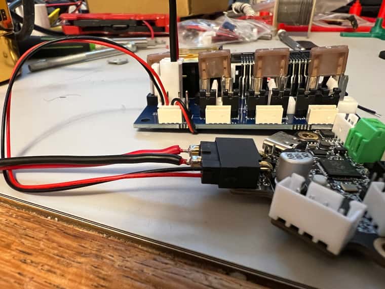
I’m thinking it might be wise to run a bench top setup with one tool before I go all in.
-
@edsped Hard to say as I can't see the jumpers you have installed on the distribution board very well. But I would say that it is wrong, you need to have the bypass jumpers installed on all of the outputs, it looks like they may be missing on the one you are using.I also can't see what you have done with the extra wires coming out of the connector plugged into the distribution board.
Didn't the Fly36 come with a pre-wired plug for the power/CAN connector?
-
@edsped this may make things easier for the wiring if you're prepared to wait
https://s.click.aliexpress.com/e/_EIJSNKf -
This post is deleted! -
@KenW It depends how you wire things up, that is the length of a drop cable/spur from the bus to the board. You could take the bus all the way to the board and have a very short drop cable from the bus to the board, but then you will need 4 wires for the bus (two out and two back), the bus itself can be pretty long.
You may also be able to operate things with a longer drop cable than the 1m I quoted above, but that is not something I've ever tested. Also if you only have a single toolboard then you can simply run the bus to the toolboard and terminate it there.
-
@KenW Oh and this all applies to the RRF-36 board, the Duet toolboards make it a little easier to route the bus out to the board and back with 4 wires.
-
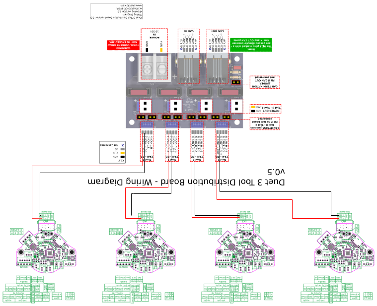
Shoot I may have to rethink this.. I’ll definitely need more than 1m for a toolchanger. I’m attaching a janky wiring diagram for the RRF 36 to distribution board, colors are switched from how I wired but I’m just trying to understand the wiring so please ignore. Can you explain the 4 wires back to the bus like I’m 5, ee was never my strong point if it’s not already obvious
-
@edsped you could probably just double up the CAN wires on the XT30 2+2 connection and then run one set to put on the distribution board and one set to in, mimicking the way the duet 1LC does it. Then the last board would just need a single pair on CAN wires.
You should be able to get the crimps for the CAN portion of the XT30 connectors on AliExpress -
@edsped Just to be clear the 1m is from the toolboard to the distribution board. How big a printer do you have? My e3d toolchanger uses this setup and has much less than 1m between the two for each tool. As I said it may well work with more than this, I was just going off the details in the CAN standard.
-
Poor understanding of terminology on my part, will definitely be less than a meter as I plan on locating the board near the tools.
-
Ultimately it will end up on this. My hope is a smooth transition with minimal downtime.

-
This post is deleted! -
@Herve_Smith
I think I have about 8' per tool but am hoping reduce that by using the CAN setup. If you can't tell I'm a bit out of my league on this. I'm beyond busy at the moment but my next step is to setup some sort of bench test setup and play with it for a bit before stripping down my machine.