Custom Input Shaping accelerator board?
-
TL;DR, seeking feedback regarding customizable accelerator board for Duet.
I had difficulty fitting the Duet input shaping accelerator board in my Voron 2.4 / Revo printer (see another thread here), so am playing with the idea of a generic RRF input shaping board that can be customizable to fit any printer.
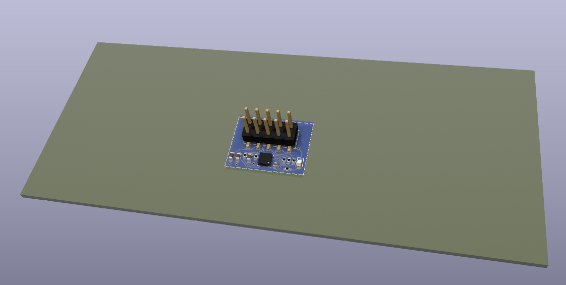
The rendering below shows the concept of a large PCB that contains a small circuti and around it plenty of blank area (bare fiberglass). This way the board can be cut and drilled to fit any printer, either using a saw and a drill, or for more popular printers, by changing the board outline before ordering the PCBs.
This was inspired by Voron boards such as this one https://www.aliexpress.us/item/3256805225051803.html
The main goals of this design:
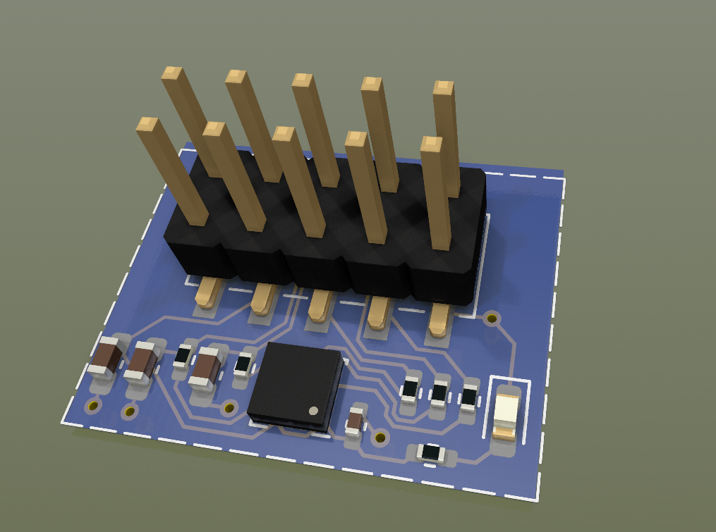
- Active area as small as possible.
- No through hole components for a smooth back surface (and no traces other than ground)
- Using only components that are available from JLCPCB board assembly service, preferably at 'basic' level. (which will allow to order ready made boards)
- Compatible with the Duet's 10 wire ribbon wiring and firmware.
- Public domain design that uses using free tools (Kicad)
Any thoughts on any aspect of this idea?
-
@zapta looks good. You might want to consider using a transition connector instead of the 10-pin header, to reduce the profile of the board.
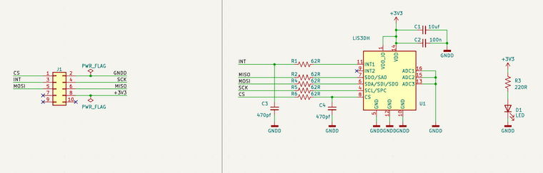
You haven't provided the schematic. I'm guessing that you reverse engineered the one that we sell, in which case you should already have the RC filter on the CS signal to suppress glitches caused by capacitive coupling to the other wires. This filter is important because the LIS3DH is very sensitive to glitches on CS.
Duet WiFi hardware designer and firmware engineer
Please do not ask me for Duet support via PM or email, use the forum
http://www.escher3d.com, https://miscsolutions.wordpress.com -
-
Schematics attached. Using 50ohm for damper resistors because they are cheaper on JLCPCB ('basic' level components). Is it a problem?
-
Regarding the cable adapter idea, what do you think about this cable (8 wires, 100cm version)? It has half the pitch of the cable that comes with the duet accelerator. (or can use 10 wires with double wires for ground and power).
https://www.aliexpress.us/item/3256804152816952.html
-
-
@zapta, isn't the pitch on the Duet board headers 2.54 mm? Wouldn't you need that pitch in order to plug into the Duet?
-
@jens55, the concept shown here has 2.54mm headers and should fit with no change, but I think what David suggested is to have a smaller cable and have a small adapter board near the Duet controller.
-
@zapta i was suggesting the same size cable but connecting it directly to the accelerometer board using a transition connector instead of a plug and socket.
Duet WiFi hardware designer and firmware engineer
Please do not ask me for Duet support via PM or email, use the forum
http://www.escher3d.com, https://miscsolutions.wordpress.com -
@dc42, I see, one like the link below. This would reduce the connection height from 14mm to 7.5mm. BTW, just removing the stock cable retainer cuts the height by about 4-5mm.
https://www.aliexpress.us/item/2255801027644535.html
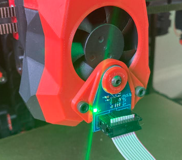
I ended using custom adapter that attaches the board at the front, as common with Voron printers. Easier to install and I doesn't mess with my baby steps settings. This uses the stock Duet PCB and can be customized to other print heads.
If anybody wants to build one, it has two printer parts, uses a Voron insert (M3, OD=5mm, L=4mm), one M3 x 6mm, and two M3 x 60mm. Exported model is available here https://tinyurl.com/4cev4db4
-
@zapta perfect location for the accelerometer. About as close to the nozzle as it gets.
-
 undefined zapta referenced this topic