(wasn't sure if allowed) Selling my HE3D Duet3d hardware printer
-
@sneakyferret where are you based, where will you ship to, how much etc is useful info!
Or you’re in the right place to get it working….
Ian
-
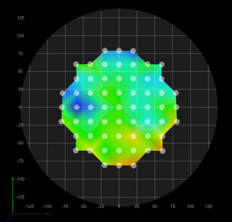
@dc42 I definitely do not want to sell but I have posted a few times and done as people have suggested with no results sadly. Short of replacing the main board and all stepper motors and HOPING thats the fix, I am not sure what else to do. Basically, I cannot get a good first layer due to some sort of possible mechanical trouble. No matter what I do I cannot get a decent height map and the height map changes slightly every time I run a fresh delta calibration and mesh compensation . I am running a Duet2wifi with a Duet3d Smart Effector v2. Here's what I have done so far:
- Squared up all towers to within a few mm.
- Replaced all belts.
- Had someone print me adjustable carriers to make sure all belts are tight but not overly so.
- Measured and checked all rods making sure they're all equal length.
- Rewired and crimped wire ends twice to make sure of no fouled connections between main board and smart effector.
- Replaced smart effector from v1 to v2 (previous effector had a metal nut with no fiber washer so the delicate circuits were damaged).\
- Set the effector to turn off/on during mesh compensation/delta calibration to prevent the bed heater from interfering with touch detection.
- Checked stepper motors and their set screws multiple times.
- Tightened every possible bolt I could find.
- Literally, strapped the printer down to the table its on to prevent it from walking/moving too much.
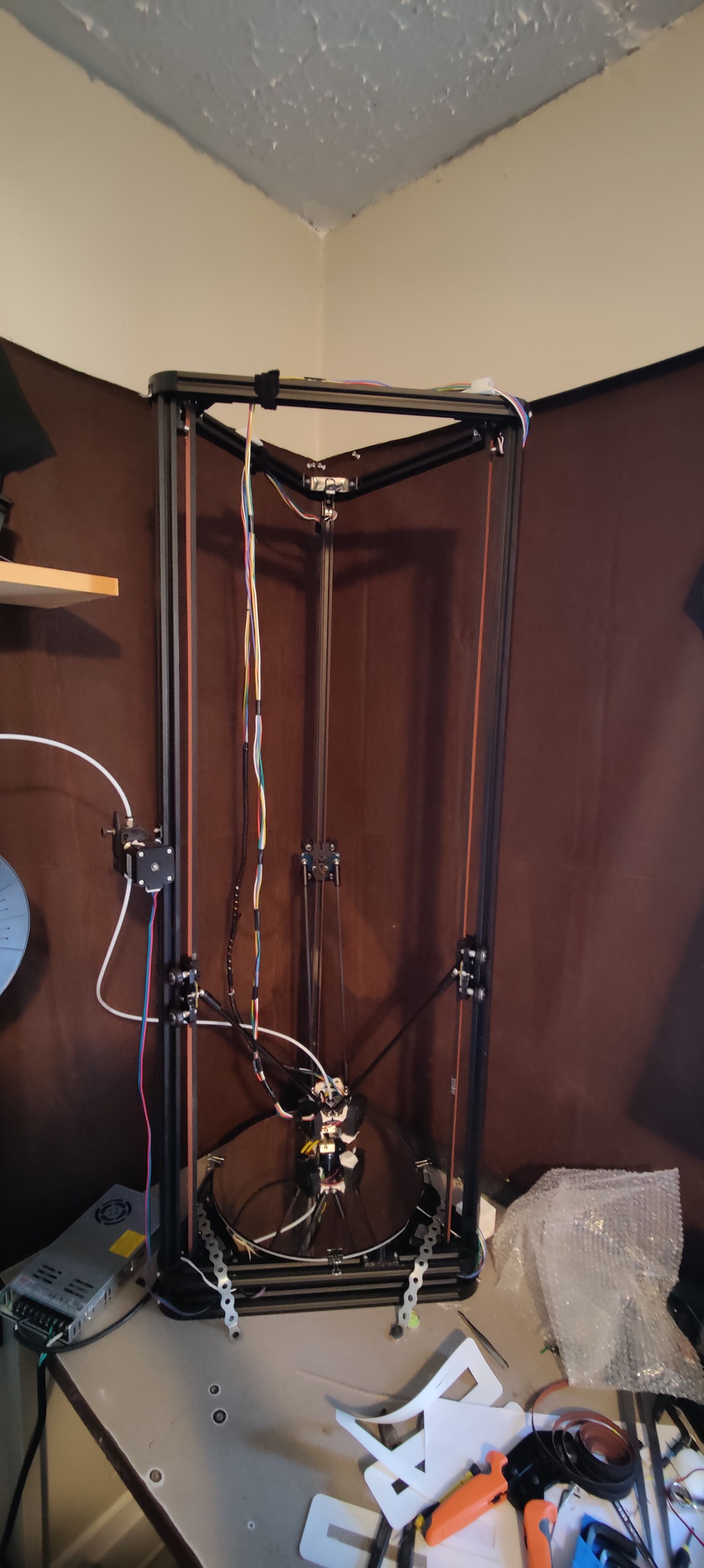
For the longest time I had the printer doing quite well but then I wanted to lengthen the effector wire harness due to cables sagging off the side and getting caught on things. I rewired the effector so the wires go from under the heat bed where there is a 3d printed container holding the main board. Those wires then run up the back side of two towers (voltage separated from the other sensor wires) and then back town to the effector through the center of the printer. The only things I have not replaced that are mechanical are the top idlers (i checked them and they did not seem bad at all. Smooth, no grinding or resistance, stepper motors, and main board.
Here are all my configs:
config.g
; Configuration file for Duet WiFi (firmware version 2.03)
; executed by the firmware on start-up
;
; generated by RepRapFirmware Configuration Tool v2.0.3 on Thu Sep 05 2019 15:50:44 GMT-0400 (Eastern Daylight Time)

; General preferences
G90                                         ; send absolute coordinates...
M83                                         ; ...but relative extruder moves
M550 P"Tall Printer"                        ; set printer name
M665 R180 L160 B130 H580                    ; Set delta radius, diagonal rod length, printable radius and homed height
M666 X0 Y0 Z0                               ; put your endstop adjustments here, or let auto calibration find them
M575 P1 S1 B57600

; Network
M552 S1                                     ; enable network
M586 P0 S1                                  ; enable HTTP
M586 P1 S0                                  ; disable FTP
M586 P2 S0                                  ; disable Telnet

; Drives
M569 P0 S0                                  ; physical drive 0 goes backwards
M569 P1 S0                                  ; physical drive 1 goes backwards
M569 P2 S0                                  ; physical drive 2 goes backwards
M569 P3 S1                                  ; physical drive 3 goes forwards
M584 X0 Y1 Z2 E3                            ; set drive mapping
M350 X16 Y16 Z16 E16 I1                     ; configure microstepping with interpolation
M92 X80.00 Y80.00 Z80.00 E410.00            ; set steps per mm
M566 X1200.00 Y1200.00 Z1200.00 E1200.00    ; set maximum instantaneous speed changes (mm/min)
M203 X18000.00 Y18000.00 Z18000.00 E1200.00 ; set maximum speeds (mm/min)
M201 X1000.00 Y1000.00 Z1000.00 E1000.00    ; set accelerations (mm/s^2)
M906 X1100 Y1100 Z1100 E900 I50            ; set motor currents (mA) and motor idle factor in per cent
M84 S30                                     ; Set idle timeout

; Axis Limits
M208 Z0 S1                                  ; set minimum Z

; Endstops
M574 X2 S1 P"!xstop"                         ; X active low and disabled endstop
M574 Y2 S1 P"!ystop"                         ; Y active low and disabled endstop
M574 Z2 S1 P"!zstop"                         ; Z active low and disabled endstop

; Z-Probe
M558 P8 C"zprobe.in+zprobe.mod" R0.4 H5 F1000 T6000 B1   ; set Z probe type to effector and the dive height + speeds
G31 P100 X0 Y0 Z-.15                        ; set Z probe trigger value, offset and trigger height
M557 R85 S20                                ; define mesh grid

; Temperature Sensors
M308 S0 P"bed_temp" Y"thermistor" T100000 B3950 ; define bed temperature sensor
M308 S1 P"e0_temp" Y"thermistor" T100000 B4725 C7.06e-8 ; define E0 temperature sensor

; Heaters
M950 H0 C"bed_heat" T0 ; heater 0 uses the bedheat pin, sensor 0
M950 H1 C"e0_heat" T1 ; heater 1 uses the e0_heat pin and sensor 1
M307 H0 B0 S1.00
M140 H0

; Fans
M950 F2 C"fan2" Q500                     ; Hot end fan
M106 P2 T45 H1

M950 F0 C"fan0" Q500                     ; Part Cooling fan
M106 C"PartFan" P0 S0 H-1 B1

M307 H0 ; report the process parameters for heater 0
M307 H0 R2.186 K0.17:0.11 D5.67 S1.00 V24.0 ; set the process parameters for heater 0

; Tools
M563 P0 H1 F0 D0 T0                           ; define tool 0

G10 P0 X0 Y0 Z0                             ; set tool 0 axis offsets
G10 P0 R0 S0                                ; set initial tool 0 active and standby temperatures to 0C


; Custom settings are not defined
M501 ; recall last used parameters
bed.g
; bed.g file for RepRapFirmware, generated by Escher3D calculator
; 16 points, 7 factors, probing radius: 130, probe offset (0, 0)
G28
G30 P0 X0.00 Y130.00 Z-99999 H0
G30 P1 X83.56 Y99.59 Z-99999 H0
G30 P2 X128.03 Y22.57 Z-99999 H0
G30 P3 X112.58 Y-65.00 Z-99999 H0
G30 P4 X44.46 Y-122.16 Z-99999 H0
G30 P5 X-44.46 Y-122.16 Z-99999 H0
G30 P6 X-112.58 Y-65.00 Z-99999 H0
G30 P7 X-128.03 Y22.57 Z-99999 H0
G30 P8 X-83.56 Y99.59 Z-99999 H0
G30 P9 X0.00 Y65.00 Z-99999 H0
G30 P10 X56.29 Y32.50 Z-99999 H0
G30 P11 X56.29 Y-32.50 Z-99999 H0
G30 P12 X0.00 Y-65.00 Z-99999 H0
G30 P13 X-56.29 Y-32.50 Z-99999 H0
G30 P14 X-56.29 Y32.50 Z-99999 H0
G30 P15 X0 Y0 Z-99999 S7
homedelta.g
; homedelta.g
; called to home all towers on a delta printer
;
; generated by RepRapFirmware Configuration Tool v2.1.8 on Sun Feb 02 2020 21:40:18 GMT-0500 (Eastern Standard Time)
G91                         ; relative positioning
G1 H1 X605 Y605 Z605 F1800  ; move all towers to the high end stopping at the endstops (first pass)
G1 H2 X-5 Y-5 Z-5 F1800     ; go down a few mm
G1 H1 X10 Y10 Z10 F1800     ; move all towers up once more (second pass)
G1 Z-10 F6000        ; move down a few mm so that the nozzle can be centred
G90                         ; absolute positioning
G1 X0 Y0 F6000            ; move X+Y to the centre
If anyone can find anything and help me out I would be very much appreciated. If not, I will sell to someone who knows more about these.

-
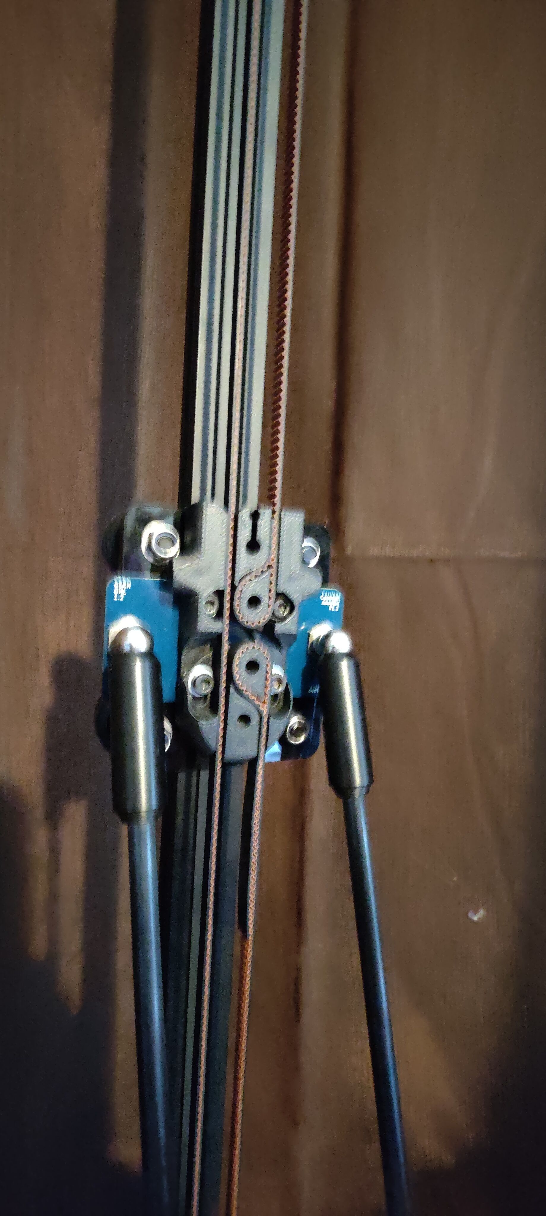
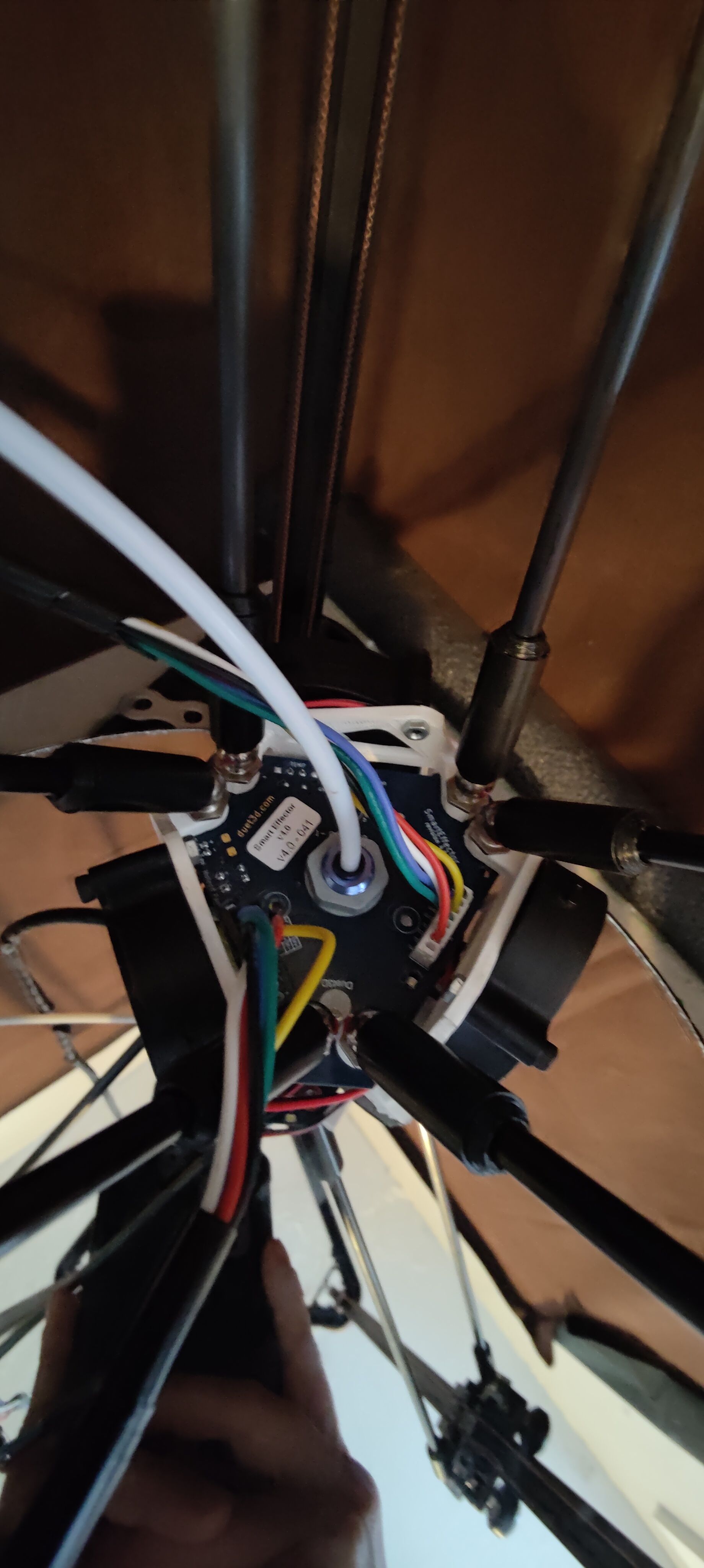
@sneakyferret a few pictures but can take better ones for anyone who needs to see more.
-
@sneakyferret those height maps look very similar, but possibly with a different z offset height. I'm not familiar with the smart effector. What does it use for a probe?
-
@Surgikill It has load detection so the entire effector detected when it makes contact with the bed.
-
Hi, had similar issues with a predator i converted by myself to use a Duet2 Wi-Fi and a Smart Effector plus Haydns Magball Arms what did it for me was calibrating the correct z=0 and trigger height sounds to easy to be true but it worked and saved the build for me.
So if you are sure everything runs smooth and is properly build, belts are not over tightened try this:Basically I’ve used a sticky note to determine the right z=0 afterwards i basically followed the tutorial you can find online to determine the right trigger height. With that done I preheat my buildplate (ultrabase pro by anycubic) to 60C and run the delta auto calibration. And all of a sudden it prints perfect first layers, small changes I also had to do: change back from those Chinese fake high flow nozzles with copper inserts to a normal .4 brass nozzle and use a fresh roll of pla used quite an old roll of pla and couldn’t get it to stick. If you already did all of that I’m sorry to waste your time by writing an essay

Hey just realised I didn’t read your description well you have really long cables running to your effector and they are not shielded in any way have u tried using cat 7 cables or something like that they seem quite long for unshielded non twisted cables. Another problem I first had was not enough slack in the cable so my tool head ever so slightly was pulled inwards creating a problem with probing.
-
@leprint said in (wasn't sure if allowed) Selling my HE3D Duet3d hardware printer:
Hi, had similar issues with a predator i converted by myself to use a Duet2 Wi-Fi and a Smart Effector plus Haydns Magball Arms what did it for me was calibrating the correct z=0 and trigger height sounds to easy to be true but it worked and saved the build for me.
So if you are sure everything runs smooth and is properly build, belts are not over tightened try this:Basically I’ve used a sticky note to determine the right z=0 afterwards i basically followed the tutorial you can find online to determine the right trigger height. With that done I preheat my buildplate (ultrabase pro by anycubic) to 60C and run the delta auto calibration. And all of a sudden it prints perfect first layers, small changes I also had to do: change back from those Chinese fake high flow nozzles with copper inserts to a normal .4 brass nozzle and use a fresh roll of pla used quite an old roll of pla and couldn’t get it to stick. If you already did all of that I’m sorry to waste your time by writing an essay
I’ve just checked in your bed.g you run a 7 factor calibration i only use 6 factors as recommended by the guys at Duet with 12 points 1 directly below each tower 1 point opposite each tower at the outer circumference of the bed and then i just go smaller and smaller diameter circles and the final point is spot on in the middle of the bed.
Also I’ve used slower diving speeds one the probe motion itself in order to not false trigger it. -
@leprint I'll give these suggestions a go when I return home from work. The cables are long enough to not cause pull on the effector when fully at the bottom and they don't sag to much off the side to cause tilt so far as I can tell. I will rewire the effector data cables but all I have is Cat6e. Think that's shielded enough?
I appreciate the tip with getting a proper z level but unfortunately I have already done this about 3 or 4 times with no change in behavior. Thank you for reaching out. I really don't want to get rid of this.
-
@sneakyferret a cat6e should do the trick aswell more than proberly shielded. another thing ive noticed is you also use v rollers as your movement system on your axis. i know it is a dumb question but did you make sure all of them properly engage with the extrusions they are runnning in ive had to clean my extrusions quite a lot with some isapropanol and properly engage every single V-Roller. I`ve also dissambled, cleaned and relubed them in order to get a smooth motion system had a lot of pinched rollers.
-
@leprint Funny you should mention that because I have adjusted the tension and lubricated these things many times but what I find curious is the height map DOES change when I adjust the tension of any of them. I have made a spreadsheet of how I adjusted each tower and recorded the height map afterwards. Then, I would save that height map screenshot, adjust another tower, then record the results to see if I could find out what's causing it but I could never find a clear answer for the cause of those dips and peaks you see in the heightmap. I even lubricated the channels they move up and down through and made sure every bearing was not seizing or clicking with no avail.