Wiring Multiple Endstops in Parallel or Series with Duet 6XD
-
@droftarts
i did define the wrong pins. The correct pins areI am able to move the X and Y-axis to homing points except the triggers or Endstops were not working correctly. I will update as per your advice and comment out the endstop lines for X and Y axis in the config.g and just leave Trigger 1 then test again
Updated Config.g Snapshot
On trigger 1 for X and Y-axis and commented out Endstops for X and Y-axis; Triggers -- Two triggers, one for X and one for Y, and set them to pause the machine M950 J1 C"!0.io0.in" ; define Trigger input pin #1 on IO_0 M950 J2 C"!0.io1.in" ; define Trigger input pin #2 on IO_1 M581 T1 P1:2 S1 R0 ; invoke trigger 1 (pause) when an inactive-to-active edge (correct for NO switches) is detected on input 1 or input 2 at any time ; Endstops ; For X and Y Axis ;M574 X1 S1 P"!0.io0.in" ; configure active high endstop switch for low end on X via pin io0.in ;M574 Y1 S1 P"!0.io1.in" ; configure active high endstop switch for low end on Y via pin io1.inUpdated homex.g
; homex.g
; called to home the X axis

; Undefine any Triggers for X and Y-axis
M950 J1 C"nil" ; undefine X axis limit switch triggers
M950 J2 C"nil" ; undefine Y axis limit switch triggers
;Define The Triggers for X and Y-axis
M574 X1 S1 P"0.io0.in" ; define X axis endstop, minimum end
M574 Y1 S1 P"0.io1.in" ; define Y axis endstop, minimum end

;	Home X-Axis
G91                   ; relative positioning
G1 H2 X0              ; move X-axis Minimum Homing endstop and stop there (first pass)
G1 H2 X-1575 F1800    ; move quickly to X-axis Maximum endstop and stop there (first pass)
G1 H2 X-15 F6000      ; go back a few mm
G1 H2 X-1575 F360     ; move slowly to X-axis Maximum endstop once more (second pass)
G1 H2 X0              ; move back to X-axis Minimum Homing endstop and stop there (second pass)
G92 X0
G90                   ; absolute positioning

;
M574 X0
M574 Y0
; Triggers
M950 J1 C"0.io0.in"
M950 J2 C"0.io1.in"
Updated homey.g
; homey.g
; called to home the Y axis
;
; generated by RepRapFirmware Configuration Tool v3.3.16 on Tue Dec 05 2023 09:51:46 GMT-0500 (Eastern Standard Time)


M950 J1 C"nil" ; undefine X axis limit switch triggers
M950 J2 C"nil" ; undefine X axis limit switch triggers

M574 X1 S1 P"!0.io0.in" ; define X axis endstop, minimum end
M574 Y1 S1 P"!0.io1.in" ; define Y axis endstop, minimum end

G91                   ; relative positioning
G1 H2 Y0              ; move Y-axis Minimum Homing endstop and stop there (first pass)
G1 H2 Y2125 F1800     ; move quickly to Y-axis Maximum endstop and stop there (first pass)
G1 H2 Y15 F6000       ; go back a few mm
G1 H2 Y2125 F360      ; move slowly to Y-axis Maximum endstop once more (second pass)
G1 H2 Y0              ; move back to Y-axis Minimum Homing endstop and stop there (second pass)
G92 Y0
G90                   ; absolute positioning

M574 X0
M574 Y0

M950 J1 C"!0.io0.in"
M950 J2 C"!0.io1.in"
@droftarts , Does this look correct to you ?
-
@developeralgo222
@droftarts , @dc42
On the DWC console , when i sendM98 P"config.g"i get "connection Interrupted HTTP request timed out" error with connection Lost, attempting to reconnect message and it disconnects DWC completely and i have to reboot manually. It does not even reboot or reset itself. Is that a bug on the RRF Software ? It seems it completely locks out Duet 6XD and i have to manually turn off the power and then power it back on. Even M112 does not reset it . Any reason why it would do that from the config.g ?
I am running RRF 3.4.6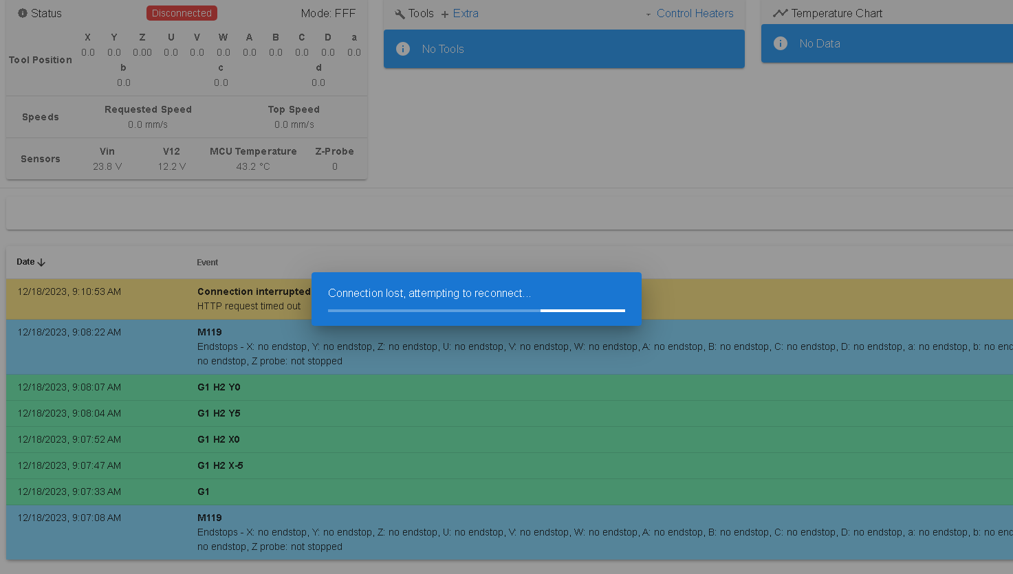
Below is my current Full config.g
; Configuration file for Duet 3 MB 6XD (firmware version 3.3) ; executed by the firmware on start-up ; ; generated by RepRapFirmware Configuration Tool v3.3.16 on Tue Dec 05 2023 09:51:46 GMT-0500 (Eastern Standard Time) ; General preferences G90 ; send absolute coordinates... M83 ; ...but relative extruder moves M550 P"MYTEST PNP" ; set printer name ; Wait a moment for the CAN expansion boards to start G4 S2 ; Network if {network.interfaces[0].type = "ethernet"} M552 P10.0.0.200 S1 ; enable network and set IP address M553 P255.255.255.0 ; set netmask M554 P10.0.0.1 ; set gateway else M552 S1 M586 P0 S1 ; enable HTTP M586 P1 S0 ; disable FTP M586 P2 S0 ; disable Telnet ;The X axis to control the movement of the PnP head right and left. Right(Clockwise rotation to move Forward = S0) is positive. ;The Y axis to control the movement of the PnP head forward and back. Forward( AntiClockwise rotation to move Forward = S1) is positive. ;The Z axis to control raising and lowering of the PnP nozzle up and down. Up is positive. ;The V, U, W, A, B, C (for 6-Head nozzles) axes rotates clockwise and counter-clockwise. Counter-clockwise is positive. ;RepRapFirmware supports X, Y and Z axes as standard and allows you to create up to 7 additional axes depending on the firmware ;version and which Duet you are using. Axes are created and associated with ;stepper motors using the M584 command in config.g. ;You may use any of the following letters to refer to the new axes: U V W A B C D (letter D is not supported in older firmware versions) ;If no T parameter is given, then on boards having internal drivers the step pulse width and interval are guaranteed to be suitable for the on-board drivers only, ;and will generally be too fast for external drivers. On the MB6XD board the default is T2.5:2.5:2.5:2.5. ; Drives ;Physical Drives CAN ID = 0 M569 P0.0 S1 T5:5:10:10 ; X-Axis physical drive 0.0 goes backwards on CAN ID = 0 - Duet 6XD Drive 0.0 with 2.5us timings between pulses M569 P0.1 S0 T5:5:10:10 ; Y-Axis physical drive 0.1 goes forwards on CAN ID = 0 - Duet 6XD Drive 0.1 with 2.5us timings between pulses ;Physical Drives CAN ID = 1 M569 P1.0 S1 ; Z & U Axis physical drive 1.0 Rotates Clockwise or Anticlockwise to move CAM driven dual nozzles down and up on Z & U axis on CAN ID = 1 - Duet 3HC Drive 1.0 M569 P1.1 S1 ; V & W Axis physical drive 1.1 Rotates Clockwise or Anticlockwise to move CAM driven dual nozzles down and up on V & W axis on CAN ID = 1 - Duet 3HC Drive 1.1 M569 P1.2 S1 ; A & B Axis physical drive 1.2 Rotates Clockwise or Anticlockwise to move CAM driven dual nozzles down and up on A & B axis on CAN ID = 1 - Duet 3HC Drive 1.2 ;Physical Drives CAN ID = 2 M569 P2.0 S1 ; C-Axis physical drive 2.0 goes Rotates forwards and backwards (+180 and -180 ) on CAN ID = 2 - Duet 3HC Drive 2.0 M569 P2.1 S1 ; D-Axis physical drive 2.1 goes Rotates forwards and backwards (+180 and -180 ) on CAN ID = 2 - Duet 3HC Drive 2.1 M569 P2.2 S1 ; 'A-Axis physical drive 2.2 goes Rotates forwards and backwards (+180 and -180 ) on CAN ID = 2 - Duet 3HC Drive 2.2 ;Physical Drives CAN ID = 3 M569 P3.0 S1 ; 'B-Axis physical drive 3.0 goes Rotates forwards and backwards (+180 and -180 ) on CAN ID = 3 - Duet 3HC Drive 3.0 M569 P3.1 S1 ; 'C-Axis physical drive 3.1 goes Rotates forwards and backwards (+180 and -180 ) on CAN ID = 3 - Duet 3HC Drive 3.1 M569 P3.2 S1 ; 'D-Axis physical drive 3.2 goes Rotates forwards and backwards (+180 and -180 ) on CAN ID = 3 - Duet 3HC Drive 3.2 ;By default Z U V W are linear and A B C D are rotary; but you can change that using the R ; Enable All the drives M17 ; Enable All the drives ; set visible drive mapping ; X-Axis , Y-Axis (2 x Nema 34 Closed Loop Motors) and Z-Axes (Z,U,V,W,A,B) mapping to 3 Stepper motors ; directly connected to 3HC (CAN ID = 1) (which moves the nozzles up and down along Z-axis) ;M584 X0.0 Y0.1 Z1.0 U1.0 V1.1 W1.1 A1.2 B1.2 R0 ; LIN R0 = LINEAR, R1 = ROTATION M584 X0.0 Y0.1 R0 ; LIN R0 = LINEAR, R1 = ROTATION ; Rotational Axes mapping (C, D, 'A, 'B, 'C, 'D ) to 6 motors directly connected to 3HC (CAN ID 2 and 3) (which rotates the nozzles +180 / -180 along Rotational axis) ;M584 C2.0 D2.1 'A2.2 'B3.0 'C3.1 'D3.2 R1 ; LIN R0 = LINEAR, R1 = ROTATION M584 Z1.0 U1.0 V1.1 W1.1 A1.2 B1.2 C2.0 D2.1 'A2.2 'B3.0 'C3.1 'D3.2 R1 ; LIN R0 = LINEAR, R1 = ROTATION M350 Z16 U16 V16 W16 A16 B16 C16 D16 'A16 'B16 'C16 'D16 I1 ; configure microstepping with interpolation. This is irrelevant for external drives (X & Y ) M92 X64.00 Y64.00 Z8.888 U8.888 V8.888 W8.888 A8.888 B8.888 C8.888 D8.888 'A8.888 'B8.888 'C8.888 'D8.888 ; set steps per mm 50mm/rev M566 X300.0 Y300.0 Z300.0 U300.0 V300.0 W300.0 A300.0 B300.0 C100.0 D100.0 'A100.0 'B100.0 'C100.0 'D100.0 ; set maximum instantaneous speed changes (mm/min) M203 X5000.00 Y5000.00 Z5000.00 U5000.00 V5000.00 W5000.00 A5000.00 B5000.00 C5000.00 D5000.00 'A5000.00 'B5000.00 'C5000.00 'D5000.00 ; set maximum speeds (mm/min) M201 X1000.00 Y1000.00 Z500.00 U500.00 V500.00 W500.00 A500.00 B500.00 C1000.00 D1000.00 'A1000.00 'B1000.00 'C1000.00 'D1000.00 ; set accelerations (mm/s^2) M906 Z600.0 U600.0 V600.0 W600.0 A600.0 B600.0 C500.0 D500.0 'A500.0 'B500.0 'C500.0 'D500.0 I30 ; set motor currents (mA) and motor idle factor in per cent. This is irrelevant for external drives (X & Y ) M84 S30 ; Set idle timeout M564 H0 ; Sets homing, H0 allows mvmnt wo homing ; Axis Limits M208 X0 Y0 Z-160 U-160 V-160 W-160 A-160 B-160 C0 D0 'A0 'B0 'C0 'D0 S1 ; Set axis minima M208 X-1575 Y2125 Z0 U0 V0 W0 A0 B0 C180 D180 'A180 'B180 'C180 'D180 S0 ; Set axis maxima ; Triggers -- Two triggers, one for X and one for Y, and set them to pause the machine M950 J1 C"!0.io0.in" ; define input #1 pin IO_0 M950 J2 C"!0.io1.in" ; define input #2 pin IO_1 ; Trigger number 0 causes an emergency stop as if M112 had been received. Trigger number 1 causes the print to be paused as if M25 had been received. Any trigger number # greater than 1 causes ; the macro file sys/trigger#.g to be executed. Polling for further trigger conditions is suspended until the trigger macro file has been completed M581 T1 P1:2 S1 R0 ; invoke trigger 1 (pause) when an inactive-to-active edge (correct for NO switches) is detected on input 1 or input 2 at any time ; There are two parameters to be set for each endstop: ; (1) The electrical type of the endstop (S parameter). S0 = active low (S0, e.g. normally-open switch or Hall sensor), S1 = active high (S1, e.g. a normally-closed switch or opto switch), ; S2 = Use Z probe (S2) and S3 = for using motor stall detection (S3). ; (2) Whether the endstop is at the minimum end (Low End) or the maximum end (High End) of the axis. ; These are the X, Y and Z parameters. 0 = no endstop present(e.g X0) , 1 = an endstop switch at the Minimum end (e.g X1) , 2 = an endstop switch at the Maximum end (e.g X2) of the axis. ; Endstops ; For X and Y Axis ;M574 X1 S1 P"!0.io0.in" ; configure active high endstop switch for low end on X via pin io0.in ;M574 Y1 S1 P"!0.io1.in" ; configure active high endstop switch for low end on Y via pin io1.in ; For Z-Axis (Z,U,V,W,A,B) - Up/down) -- CAM Driven Dual Nozzles ( 1 Motor rotates up/down to drive 2 Nozzles ) M574 Z1 S1 P"!1.io0.in" ; configure active high endstop switch for low end on Z via pin 1.io0.in M574 U1 S1 P"!1.io1.in" ; configure active high endstop switch for low end on U via pin 1.io1.in M574 V1 S1 P"!1.io2.in" ; configure active high endstop switch for low end on V via pin 1.io2.in M574 W1 S1 P"!1.io3.in" ; configure active high endstop switch for low end on W via pin 1.io3.in M574 A1 S1 P"!1.io4.in" ; configure active high endstop switch for low end on A via pin 1.io4.in M574 B1 S1 P"!1.io5.in" ; configure active high endstop switch for low end on B via pin 1.io5.in ; For Rotational Axes only (C,D,'A,'B,'C,'D) +180 / - 180 ) M574 C1 S1 P"!2.io0.in" ; configure active high endstop switch for low end on C via pin 2.io0.in M574 D1 S1 P"!2.io1.in" ; configure active high endstop switch for low end on D via pin 2.io1.in M574 'A1 S1 P"!2.io2.in" ; configure active high endstop switch for low end on 'A via pin 2.io2.in M574 'B1 S1 P"!3.io0.in" ; configure active high endstop switch for low end on 'B via pin 3.io0.in M574 'C1 S1 P"!3.io1.in" ; configure active high endstop switch for low end on 'C via pin 3.io1.in M574 'D1 S1 P"!3.io2.in" ; configure active high endstop switch for low end on 'D via pin 3.io2.in ; SMC NPN Vacuum Sensors -ZSE30A-01-N-L (Not Z-Probe) M558 P8 C"!2.io3.in" ; Duet 3 3HC CAN_ID 2 Port 4- Vacuum Sensor Nozzle 1 M558 P8 C"!2.io4.in" ; Duet 3 3HC CAN_ID 2 Port 5- Vacuum Sensor Nozzle 2 M558 P8 C"!2.io5.in" ; Duet 3 3HC CAN_ID 2 Port 6- Vacuum Sensor Nozzle 3 M558 P8 C"!3.io3.in" ; Duet 3 3HC CAN_ID 2 Port 4- Vacuum Sensor Nozzle 4 M558 P8 C"!3.io4.in" ; Duet 3 3HC CAN_ID 2 Port 5- Vacuum Sensor Nozzle 5 M558 P8 C"!3.io5.in" ; Duet 3 3HC CAN_ID 2 Port 6- Vacuum Sensor Nozzle 6 ; (SMC) LINGERA CM85-10-A-6S Integrated Solenoid Valves (Pump and Vacuum) on the Duet 6XD M558 P8 C"!0.io3.in" ; Duet 3 6XD CAN_ID 0 Port 4- Pump and Vacuum Solenoid Valve for Nozzle 1 M558 P8 C"!0.io4.in" ; Duet 3 6XD CAN_ID 0 Port 5- Pump and Vacuum Solenoid Valve for Nozzle 2 M558 P8 C"!0.io5.in" ; Duet 3 6XD CAN_ID 0 Port 6- Pump and Vacuum Solenoid Valve for Nozzle 3 M558 P8 C"!0.io6.in" ; Duet 3 6XD CAN_ID 0 Port 7- Pump and Vacuum Solenoid Valve for Nozzle 4 M558 P8 C"!0.io7.in" ; Duet 3 6XD CAN_ID 0 Port 8- Pump and Vacuum Solenoid Valve for Nozzle 5 M558 P8 C"!0.io8.in" ; Duet 3 6XD CAN_ID 0 Port 9- Pump and Vacuum Solenoid Valve for Nozzle 6 ; Heaters ; Fans ; Tools ; Custom settings are not defined -
@developeralgo222 are you saying that it boots up OK and you can connect with DWC; but if you try to re-run config.g using M98, you lose the DWC connection?
If that's the case then I think it's most likely to do with the triggers. Try commenting out the M581 line(s) in config.g.
BTW you don't need to switch those inputs between being endstops and GpIn ports for triggers, because a trigger can monitor endstops as well as GpIn pins. See the line starting "X, Y Z or any..." at https://docs.duet3d.com/en/User_manual/Reference/Gcodes#m581-configure-external-trigger.
-
@developeralgo222 I think your config.g crashing predated adding the triggers, but as @dc42 says, triggers in RRF 3.01 and later can read the endstop without redefining it as a trigger (older versions can't, and need to be redefined). Sorry I didn't spot this, it's been a while since having to set up endstops as limit switches! Comment out or delete the M950 J1 and J2 lines, add the endstop M574 X1 and Y1 commands back in, and change the trigger command to
M581 T1 X Y S1 R0.Some other things to try:
You have M17 very early in config.g, before any of the axes are assigned. I suggest moving to the end, or don't have it at all. The motors will all turn on as soon as one axis is commanded to move.
Your X axis limits are strange, I think swap them over, or maybe it should be
M208 X1575 ... S0.
Also, your other limits:; Axis Limits M208 X0 Y0 Z-160 U-160 V-160 W-160 A-160 B-160 C0 D0 'A0 'B0 'C0 'D0 S1 ; Set axis minima M208 X-1575 Y2125 Z0 U0 V0 W0 A0 B0 C180 D180 'A180 'B180 'C180 'D180 S0 ; Set axis maximaI'm not even sure axis ranges should be from -[nnn] to 0, but I don't see why not. On a CNC machine, you have machine coordinates, and then work coordinates. This article looks like it covers this (and RRF supports) https://mhcc.pressbooks.pub/supportcnc/chapter/g54-g59-an-introduction/
It looks like OpenPNP is similar: https://github.com/openpnp/openpnp/wiki/Machine-AxesThe rest is mostly setting up the endstop triggers, endstops. However, you have setup all the sensors and valves with M558, which is used for defining probes! I think the sensors should be set up with M950 as inputs:
M950 J1 C"!2.io3.in"   ; Duet 3 3HC CAN_ID 2 Port 4- Vacuum Sensor Nozzle 1
M950 J2 C"!2.io4.in"   ; Duet 3 3HC CAN_ID 2 Port 5- Vacuum Sensor Nozzle 2
[etc]
with each input having a unique J[nn] parameter. Make sure the number doesn't clash with the triggers, though I expect you will replace these with endstop definitions.
The valves should be outputs, again set with M950, with unique P[nn] parameter:
M950 P1 C"!0.io3.in"   ; Duet 3 6XD CAN_ID 0 Port 4- Pump and Vacuum Solenoid Valve for Nozzle 1
M950 P2 C"!0.io4.in"   ; Duet 3 6XD CAN_ID 0 Port 5- Pump and Vacuum Solenoid Valve for Nozzle 2
[etc]
Please make these changes, post your updated config.g, and try sending
M98 P"config.g"again.Ian
Bed-slinger - Mini5+ WiFi/1LC | RRP Fisher v1 - D2 WiFi | Polargraph - D2 WiFi | TronXY X5S - 6HC/Roto | CNC router - 6HC | Tractus3D T1250 - D2 Eth
-
@droftarts
before i runM98 P"config.g"Here is the updated config.g with suggested changes
; Configuration file for Duet 3 MB 6XD (firmware version 3.3) ; executed by the firmware on start-up ; ; generated by RepRapFirmware Configuration Tool v3.3.16 on Tue Dec 05 2023 09:51:46 GMT-0500 (Eastern Standard Time) ; General preferences G90 ; send absolute coordinates... M83 ; ...but relative extruder moves M550 P"MYTEST PNP" ; set printer name ; Wait a moment for the CAN expansion boards to start G4 S2 ; Network if {network.interfaces[0].type = "ethernet"} M552 P10.0.0.200 S1 ; enable network and set IP address M553 P255.255.255.0 ; set netmask M554 P10.0.0.1 ; set gateway else M552 S1 M586 P0 S1 ; enable HTTP M586 P1 S0 ; disable FTP M586 P2 S0 ; disable Telnet ;The X axis to control the movement of the PnP head right and left. Right(Clockwise rotation to move Forward = S0) is positive. ;The Y axis to control the movement of the PnP head forward and back. Forward( AntiClockwise rotation to move Forward = S1) is positive. ;The Z axis to control raising and lowering of the PnP nozzle up and down. Up is positive. ;The V, U, W, A, B, C (for 6-Head nozzles) axes rotates clockwise and counter-clockwise. Counter-clockwise is positive. ;RepRapFirmware supports X, Y and Z axes as standard and allows you to create up to 7 additional axes depending on the firmware ;version and which Duet you are using. Axes are created and associated with ;stepper motors using the M584 command in config.g. ;You may use any of the following letters to refer to the new axes: U V W A B C D (letter D is not supported in older firmware versions) ;If no T parameter is given, then on boards having internal drivers the step pulse width and interval are guaranteed to be suitable for the on-board drivers only, ;and will generally be too fast for external drivers. On the MB6XD board the default is T2.5:2.5:2.5:2.5. ; Drives ;Physical Drives CAN ID = 0 M569 P0.0 S0 T5:5:10:10 ; X-Axis physical drive 0.0 goes backwards on CAN ID = 0 - Duet 6XD Drive 0.0 with 2.5us timings between pulses M569 P0.1 S0 T5:5:10:10 ; Y-Axis physical drive 0.1 goes forwards on CAN ID = 0 - Duet 6XD Drive 0.1 with 2.5us timings between pulses ;Physical Drives CAN ID = 1 M569 P1.0 S1 ; Z & U Axis physical drive 1.0 Rotates Clockwise or Anticlockwise to move CAM driven dual nozzles down and up on Z & U axis on CAN ID = 1 - Duet 3HC Drive 1.0 M569 P1.1 S1 ; V & W Axis physical drive 1.1 Rotates Clockwise or Anticlockwise to move CAM driven dual nozzles down and up on V & W axis on CAN ID = 1 - Duet 3HC Drive 1.1 M569 P1.2 S1 ; A & B Axis physical drive 1.2 Rotates Clockwise or Anticlockwise to move CAM driven dual nozzles down and up on A & B axis on CAN ID = 1 - Duet 3HC Drive 1.2 ;Physical Drives CAN ID = 2 M569 P2.0 S1 ; C-Axis physical drive 2.0 goes Rotates forwards and backwards (+180 and -180 ) on CAN ID = 2 - Duet 3HC Drive 2.0 M569 P2.1 S1 ; D-Axis physical drive 2.1 goes Rotates forwards and backwards (+180 and -180 ) on CAN ID = 2 - Duet 3HC Drive 2.1 M569 P2.2 S1 ; 'A-Axis physical drive 2.2 goes Rotates forwards and backwards (+180 and -180 ) on CAN ID = 2 - Duet 3HC Drive 2.2 ;Physical Drives CAN ID = 3 M569 P3.0 S1 ; 'B-Axis physical drive 3.0 goes Rotates forwards and backwards (+180 and -180 ) on CAN ID = 3 - Duet 3HC Drive 3.0 M569 P3.1 S1 ; 'C-Axis physical drive 3.1 goes Rotates forwards and backwards (+180 and -180 ) on CAN ID = 3 - Duet 3HC Drive 3.1 M569 P3.2 S1 ; 'D-Axis physical drive 3.2 goes Rotates forwards and backwards (+180 and -180 ) on CAN ID = 3 - Duet 3HC Drive 3.2 ;By default Z U V W are linear and A B C D are rotary; but you can change that using the R ; set visible drive mapping ; X-Axis , Y-Axis (2 x Nema 34 Closed Loop Motors) and Z-Axes (Z,U,V,W,A,B) mapping to 3 Stepper motors ; directly connected to 3HC (CAN ID = 1) (which moves the nozzles up and down along Z-axis) M584 X0.0 Y0.1 R0 ; LIN R0 = LINEAR, R1 = ROTATION ; Rotational Axes mapping (C, D, 'A, 'B, 'C, 'D ) to 6 motors directly connected to 3HC (CAN ID 2 and 3) (which rotates the nozzles +180 / -180 along Rotational axis) M584 Z1.0 U1.0 V1.1 W1.1 A1.2 B1.2 C2.0 D2.1 'A2.2 'B3.0 'C3.1 'D3.2 R1 ; LIN R0 = LINEAR, R1 = ROTATION M350 Z16 U16 V16 W16 A16 B16 C16 D16 'A16 'B16 'C16 'D16 I1 ; configure microstepping with interpolation. This is irrelevant for external drives (X & Y ) M92 X64.00 Y64.00 Z8.888 U8.888 V8.888 W8.888 A8.888 B8.888 C8.888 D8.888 'A8.888 'B8.888 'C8.888 'D8.888 ; set steps per mm 50mm/rev M566 X300.0 Y300.0 Z300.0 U300.0 V300.0 W300.0 A300.0 B300.0 C100.0 D100.0 'A100.0 'B100.0 'C100.0 'D100.0 ; set maximum instantaneous speed changes (mm/min) M203 X5000.00 Y5000.00 Z5000.00 U5000.00 V5000.00 W5000.00 A5000.00 B5000.00 C5000.00 D5000.00 'A5000.00 'B5000.00 'C5000.00 'D5000.00 ; set maximum speeds (mm/min) M201 X1000.00 Y1000.00 Z500.00 U500.00 V500.00 W500.00 A500.00 B500.00 C1000.00 D1000.00 'A1000.00 'B1000.00 'C1000.00 'D1000.00 ; set accelerations (mm/s^2) M906 Z600.0 U600.0 V600.0 W600.0 A600.0 B600.0 C500.0 D500.0 'A500.0 'B500.0 'C500.0 'D500.0 I30 ; set motor currents (mA) and motor idle factor in per cent. This is irrelevant for external drives (X & Y ) M84 S30 ; Set idle timeout M564 H0 ; Sets homing, H0 allows mvmnt wo homing ; Axis Limits M208 X0 Y0 Z-160 U-160 V-160 W-160 A-160 B-160 C0 D0 'A0 'B0 'C0 'D0 S1 ; Set axis minima M208 X1575 Y2125 Z0 U0 V0 W0 A0 B0 C180 D180 'A180 'B180 'C180 'D180 S0 ; Set axis maxima ; Triggers -- Two triggers, one for X and one for Y, and set them to pause the machine ;M950 J1 C"!0.io0.in" ; define input #1 pin IO_0 ;M950 J2 C"!0.io1.in" ; define input #2 pin IO_1 ; Trigger number 0 causes an emergency stop as if M112 had been received. Trigger number 1 causes the print to be paused as if M25 had been received. Any trigger number # greater than 1 causes ; the macro file sys/trigger#.g to be executed. Polling for further trigger conditions is suspended until the trigger macro file has been completed M581 T1 X Y S1 R0 ; invoke trigger 1 (pause) when an inactive-to-active edge (correct for NO switches) is detected on input 1 or input 2 at any time ; There are two parameters to be set for each endstop: ; (1) The electrical type of the endstop (S parameter). S0 = active low (S0, e.g. normally-open switch or Hall sensor), S1 = active high (S1, e.g. a normally-closed switch or opto switch), ; S2 = Use Z probe (S2) and S3 = for using motor stall detection (S3). ; (2) Whether the endstop is at the minimum end (Low End) or the maximum end (High End) of the axis. ; These are the X, Y and Z parameters. 0 = no endstop present(e.g X0) , 1 = an endstop switch at the Minimum end (e.g X1) , 2 = an endstop switch at the Maximum end (e.g X2) of the axis. ; Endstops ; For X and Y Axis M574 X1 S1 P"!0.io0.in" ; configure active high endstop switch for low end on X via pin io0.in M574 Y1 S1 P"!0.io1.in" ; configure active high endstop switch for low end on Y via pin io1.in ; For Z-Axis (Z,U,V,W,A,B) - Up/down) -- CAM Driven Dual Nozzles ( 1 Motor rotates up/down to drive 2 Nozzles ) M574 Z1 S1 P"!1.io0.in" ; configure active high endstop switch for low end on Z via pin 1.io0.in M574 U1 S1 P"!1.io1.in" ; configure active high endstop switch for low end on U via pin 1.io1.in M574 V1 S1 P"!1.io2.in" ; configure active high endstop switch for low end on V via pin 1.io2.in M574 W1 S1 P"!1.io3.in" ; configure active high endstop switch for low end on W via pin 1.io3.in M574 A1 S1 P"!1.io4.in" ; configure active high endstop switch for low end on A via pin 1.io4.in M574 B1 S1 P"!1.io5.in" ; configure active high endstop switch for low end on B via pin 1.io5.in ; For Rotational Axes only (C,D,'A,'B,'C,'D) +180 / - 180 ) M574 C1 S1 P"!2.io0.in" ; configure active high endstop switch for low end on C via pin 2.io0.in M574 D1 S1 P"!2.io1.in" ; configure active high endstop switch for low end on D via pin 2.io1.in M574 'A1 S1 P"!2.io2.in" ; configure active high endstop switch for low end on 'A via pin 2.io2.in M574 'B1 S1 P"!3.io0.in" ; configure active high endstop switch for low end on 'B via pin 3.io0.in M574 'C1 S1 P"!3.io1.in" ; configure active high endstop switch for low end on 'C via pin 3.io1.in M574 'D1 S1 P"!3.io2.in" ; configure active high endstop switch for low end on 'D via pin 3.io2.in ; SMC NPN Vacuum Sensors -ZSE30A-01-N-L (Not Z-Probe) M950 J1 C"!2.io3.in" ; Duet 3 3HC CAN_ID 2 Port 4- Vacuum Sensor Nozzle 1 M950 J2 C"!2.io4.in" ; Duet 3 3HC CAN_ID 2 Port 5- Vacuum Sensor Nozzle 2 M950 J3 C"!2.io5.in" ; Duet 3 3HC CAN_ID 2 Port 6- Vacuum Sensor Nozzle 3 M950 J4 C"!3.io3.in" ; Duet 3 3HC CAN_ID 2 Port 4- Vacuum Sensor Nozzle 4 M950 J5 C"!3.io4.in" ; Duet 3 3HC CAN_ID 2 Port 5- Vacuum Sensor Nozzle 5 M950 J6 C"!3.io5.in" ; Duet 3 3HC CAN_ID 2 Port 6- Vacuum Sensor Nozzle 6 ; (SMC) LINGERA CM85-10-A-6S Integrated Solenoid Valves (Pump and Vacuum) on the Duet 6XD M950 P1 C"!0.io3.in" ; Duet 3 6XD CAN_ID 0 Port 4- Pump and Vacuum Solenoid Valve for Nozzle 1 M950 P2 C"!0.io4.in" ; Duet 3 6XD CAN_ID 0 Port 5- Pump and Vacuum Solenoid Valve for Nozzle 2 M950 P3 C"!0.io5.in" ; Duet 3 6XD CAN_ID 0 Port 6- Pump and Vacuum Solenoid Valve for Nozzle 3 M950 P4 C"!0.io6.in" ; Duet 3 6XD CAN_ID 0 Port 7- Pump and Vacuum Solenoid Valve for Nozzle 4 M950 P5 C"!0.io7.in" ; Duet 3 6XD CAN_ID 0 Port 8- Pump and Vacuum Solenoid Valve for Nozzle 5 M950 P6 C"!0.io8.in" ; Duet 3 6XD CAN_ID 0 Port 9- Pump and Vacuum Solenoid Valve for Nozzle 6 ; Enable All the drives M17 ; Enable All the drives ; Heaters ; Fans ; Tools ; Custom settings are not defined -
@developeralgo222 You haven't changed the X axis limits; it still shows X0 as the minimum, and X-1575 as the maximum. Either swap them, or remove the minus from X-1575.
Otherwise, looks okay.
Ian
Bed-slinger - Mini5+ WiFi/1LC | RRP Fisher v1 - D2 WiFi | Polargraph - D2 WiFi | TronXY X5S - 6HC/Roto | CNC router - 6HC | Tractus3D T1250 - D2 Eth
-
@droftarts
when i test it manually according to the right-hand cartesian coordinates . My X-Axis moves Backwards from Home(Right to Left) instead of the Normal Forward ( Left to Right ) , that's why i was using Negative infront of that otherwise it crashes the X-Axis. If you look at the Endpoints and motor placements diagram above , you will see the description -
@developeralgo222 In that case, change the direction of the motor with the S parameter in M569, eg:
M569 P0.0 S0 T5:5:10:10Then update the M208 command, and check it goes the right direction.
Ian
Bed-slinger - Mini5+ WiFi/1LC | RRP Fisher v1 - D2 WiFi | Polargraph - D2 WiFi | TronXY X5S - 6HC/Roto | CNC router - 6HC | Tractus3D T1250 - D2 Eth
-
@droftarts said in Wiring Multiple Endstops in Parallel or Series with Duet 6XD:
@developeralgo222 In that case, change the direction of the motor with the S parameter in M569, eg:
M569 P0.0 S0 T5:5:10:10Then update the M208 command, and check it goes the right direction.
Ian
yes updated config.g and that fixed X-axis negative max issue
-
@developeralgo222 Okay. Does it still crash when you send
M98 P"config.g"?Ian
Bed-slinger - Mini5+ WiFi/1LC | RRP Fisher v1 - D2 WiFi | Polargraph - D2 WiFi | TronXY X5S - 6HC/Roto | CNC router - 6HC | Tractus3D T1250 - D2 Eth
-
@developeralgo222 Another snag on homing; I checked with @dc42 if the trigger is ignored on homing moves. He said:
No, you have to deactivate the trigger.
..because after the homing move you need to move away form the endst9p to release it, to avoid triggeringSo in your homing macros, rather than disabling the trigger pin and enabling the endstop, you need to disable the trigger itself, while homing. So now the homing macros will look like this:
M581 T1 P-1 ; disable trigger

[normal homing routine for X and Y axis in here]

M581 T1 X Y S1 R0 ; re enable trigger
Ian
-
@droftarts Going to test that now. i was just testing if its able to Home X and Y-axis and it seems its able . Anything i need to modify on homex.g and homey.g files in relation to config.g
homex.g
; homex.g
; called to home the X axis

M581 T1 P-1 ; disable trigger

;	Home X-Axis
G91                   ; relative positioning
G1 H2 X0              ; move X-axis Minimum Homing endstop and stop there (first pass)
G1 H2 X1575 F5000     ; move quickly to X-axis Maximum endstop and stop there (first pass)
G1 H2 X-1575 F5000      ; go back to X0 Minimum Homing endstop
G1 H2 X1575 F5000     ; move quickly to X-axis Maximum endstop and stop there (second pass)
G1 H2 X-1575 F5000       ; go back quickly to X0 Minimum Homing endstop once more (second pass)
G1 H2 X0              ; Mark it as the X-axis Minimum Homing endstop and stop there (second pass)
G92 X0
G90                   ; absolute positioning


M581 T1 X Y S1 R0 ; re enable trigger
Homey.g
; homey.g ; called to home the Y axis M581 T1 P-1 ; disable trigger ; Home Y-Axis G91 ; relative positioning G1 H2 Y0 ; move Y-axis Minimum Homing endstop and stop there (first pass) G1 H2 Y2135 F5000 ; move quickly to Y-axis Maximum endstop and stop there (first pass) G1 H2 Y-2135 F5000 ; go back to Y0 Minimum Homing endstop G1 H2 Y2135 F5000 ; move quickly to Y-axis Maximum endstop and stop there (second pass) G1 H2 Y-2135 F5000 ; go back quickly to Y0 Minimum Homing endstop once more (second pass) G1 H2 Y0 ; Mark it as the Y-axis Minimum Homing endstop and stop there (second pass) G92 Y0 G90 ; absolute positioning M581 T1 X Y S1 R0 ; re enable trigger -
@developeralgo222 See my reply before yours. You will need to edit your homing files.
Edit:
Using M950 J1 and J2 in your homing files to refer to limit switches will be messing with these in config.g:; SMC NPN Vacuum Sensors -ZSE30A-01-N-L (Not Z-Probe) M950 J1 C"!2.io3.in" ; Duet 3 3HC CAN_ID 2 Port 4- Vacuum Sensor Nozzle 1 M950 J2 C"!2.io4.in" ; Duet 3 3HC CAN_ID 2 Port 5- Vacuum Sensor Nozzle 2Ian
Bed-slinger - Mini5+ WiFi/1LC | RRP Fisher v1 - D2 WiFi | Polargraph - D2 WiFi | TronXY X5S - 6HC/Roto | CNC router - 6HC | Tractus3D T1250 - D2 Eth
-
@droftarts said in Wiring Multiple Endstops in Parallel or Series with Duet 6XD:
Edit:
Using M950 J1 and J2 in your homing files to refer to limit switches will be messing with these in config.g:; SMC NPN Vacuum Sensors -ZSE30A-01-N-L (Not Z-Probe) M950 J1 C"!2.io3.in" ; Duet 3 3HC CAN_ID 2 Port 4- Vacuum Sensor Nozzle 1 M950 J2 C"!2.io4.in" ; Duet 3 3HC CAN_ID 2 Port 5- Vacuum Sensor Nozzle 2Ian
Not sure i understand what you mean by this ?
-
i sent
M98 P"config.g"command and it disconnected again same issue. I don't know what is in the config.g that makes Duet 6XD crash ?
-
@developeralgo222 never mind, you updated your homing files and have fixed it now. You can always check how pins are defined by sending,
M950 J1for example.Ian
Bed-slinger - Mini5+ WiFi/1LC | RRP Fisher v1 - D2 WiFi | Polargraph - D2 WiFi | TronXY X5S - 6HC/Roto | CNC router - 6HC | Tractus3D T1250 - D2 Eth
-
@droftarts ok got it
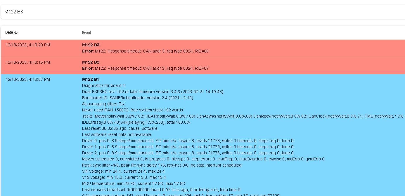
Getting response timeout errors on SMC Vacuum Pressure Sensors when i try to send manually M950 Jx as below
12/18/2023, 1:28:42 PM	M950 J6
Error: M950: Response timeout: CAN addr 3, req type 6037, RID=65
12/18/2023, 1:28:37 PM	M950 J5
Error: M950: Response timeout: CAN addr 3, req type 6037, RID=64
12/18/2023, 1:28:33 PM	M950 J4
Error: M950: Response timeout: CAN addr 3, req type 6037, RID=63
12/18/2023, 1:28:26 PM	M950 J3
Error: M950: Response timeout: CAN addr 2, req type 6037, RID=62
12/18/2023, 1:28:22 PM	M950 J2
Error: M950: Response timeout: CAN addr 2, req type 6037, RID=61
12/18/2023, 1:28:12 PM	M950 J1
Error: M950: Response timeout: CAN addr 2, req type 6037, RID=60
But i get the following for Integrated Solenoid valve (Pump & Vacuum) when i send M950 Px which seems to be fine
12/18/2023, 1:32:17 PM	M950 P6
GPIO/servo port 6 pin !io8.in frequency 500Hz
12/18/2023, 1:32:15 PM	M950 P5
GPIO/servo port 5 pin !io7.in frequency 500Hz
12/18/2023, 1:32:12 PM	M950 P4
GPIO/servo port 4 pin !io6.in frequency 500Hz
12/18/2023, 1:32:09 PM	M950 P3
GPIO/servo port 3 pin !io5.in frequency 500Hz
12/18/2023, 1:32:05 PM	M950 P2
GPIO/servo port 2 pin !io4.in frequency 500Hz
12/18/2023, 1:31:57 PM	M950 P1
GPIO/servo port 1 pin !io3.in frequency 500Hz
After Updating to RRF 3.5.0.-rc.2 and rebooting i attempted to test the input pins for the SMC NPN sensors but getting an error
12/18/2023, 5:34:40 PM M950 J6 Error: M950: Board 3 does not have input handle 2180 12/18/2023, 5:34:37 PM M950 J5 Error: M950: Board 3 does not have input handle 2140 12/18/2023, 5:34:33 PM M950 J4 Error: M950: Board 3 does not have input handle 2100 12/18/2023, 5:34:30 PM M950 J3 Error: M950: Board 2 does not have input handle 20c0 12/18/2023, 5:34:15 PM M950 J2 Error: M950: Board 2 does not have input handle 2080 12/18/2023, 5:34:08 PM M950 J1 Error: M950: Board 2 does not have input handle 2040 -
Also trying to get all the endstops on all Axis working. On the Z-Axes, i have 3 x Nema 17 Motors that are directly connected to 3HC board CAN ID = 1 , Drive 0,1 & 2. This are CAM Driven Axes
Motor 1 ---- On Drive 0 --- Rotates Clockwise or Anticlockwise to move CAM driven dual nozzles down and up on Z & U axis on CAN ID = 1 - Duet 3HC Drive 1.0 i.e Z & U-axes share a single motor 1
Motor 2 ---- On Drive 1 --- Rotates Clockwise or Anticlockwise to move CAM driven dual nozzles down and up on V & W axis on CAN ID = 1 - Duet 3HC Drive 1.1 i.e V & W-axes share a single motor 2
Motor 3 ---- On Drive 3 --- Rotates Clockwise or Anticlockwise to move CAM driven dual nozzles down and up on A & B axis on CAN ID = 1 - Duet 3HC Drive 1.2 i.e A & B-axes share a single motor 3
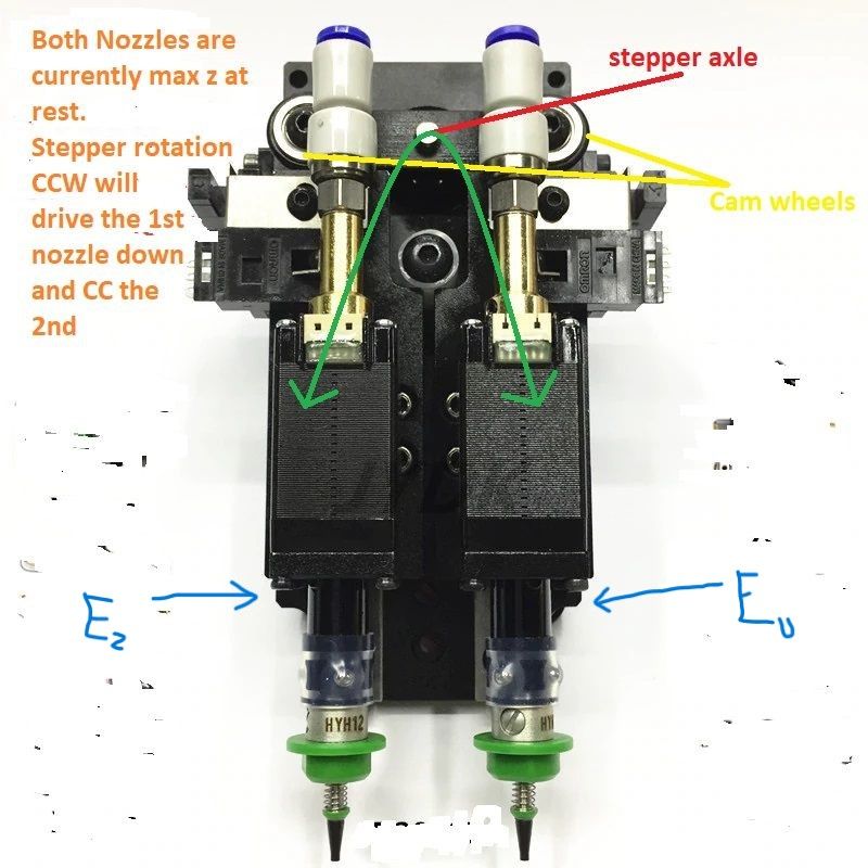
Trying to define them correctly in the config before updating the homing files. Here is a sample picture courtesy of @wayneosdias of where roughly the endstops for Z, U, V,W,A,B are located.
Two nozzles are at either end of the of the cam and at the center a stepper motor. At rest/homed both nozzles are at the Z max height and suspended this way by springs supporting against gravity. Once the stepper is activated, CCW the 1st nozzle is pushed down and the 2nd nozzle is suspended by the spring. Conversely when the stepper is activated CC the 2nd nozzle is driven down and the 1st nozzle is suspended at max z by the spring.
How do i get endstops for Z, U, V,W,A,B configured correctly ? Here is the snapshot of those Z-axes with drives and Endstops. I am not even sure that the Drives are configured correctly as per @dc42
; Drives ;Physical Drives CAN ID = 0 M569 P0.0 S0 T5:5:10:10 ; X-Axis physical drive 0.0 goes backwards on CAN ID = 0 - Duet 6XD Drive 0.0 with 2.5us timings between pulses M569 P0.1 S0 T5:5:10:10 ; Y-Axis physical drive 0.1 goes forwards on CAN ID = 0 - Duet 6XD Drive 0.1 with 2.5us timings between pulses ;Physical Drives CAN ID = 1 M569 P1.0 S1 ; Z & U Axis physical drive 1.0 Rotates Clockwise or Anticlockwise to move CAM driven dual nozzles down and up on Z & U axis on CAN ID = 1 - Duet 3HC Drive 1.0 M569 P1.1 S1 ; V & W Axis physical drive 1.1 Rotates Clockwise or Anticlockwise to move CAM driven dual nozzles down and up on V & W axis on CAN ID = 1 - Duet 3HC Drive 1.1 M569 P1.2 S1 ; A & B Axis physical drive 1.2 Rotates Clockwise or Anticlockwise to move CAM driven dual nozzles down and up on A & B axis on CAN ID = 1 - Duet 3HC Drive 1.2 ;Physical Drives CAN ID = 2 M569 P2.0 S1 ; C-Axis physical drive 2.0 goes Rotates forwards and backwards (+180 and -180 ) on CAN ID = 2 - Duet 3HC Drive 2.0 M569 P2.1 S1 ; D-Axis physical drive 2.1 goes Rotates forwards and backwards (+180 and -180 ) on CAN ID = 2 - Duet 3HC Drive 2.1 M569 P2.2 S1 ; 'A-Axis physical drive 2.2 goes Rotates forwards and backwards (+180 and -180 ) on CAN ID = 2 - Duet 3HC Drive 2.2 ;Physical Drives CAN ID = 3 M569 P3.0 S1 ; 'B-Axis physical drive 3.0 goes Rotates forwards and backwards (+180 and -180 ) on CAN ID = 3 - Duet 3HC Drive 3.0 M569 P3.1 S1 ; 'C-Axis physical drive 3.1 goes Rotates forwards and backwards (+180 and -180 ) on CAN ID = 3 - Duet 3HC Drive 3.1 M569 P3.2 S1 ; 'D-Axis physical drive 3.2 goes Rotates forwards and backwards (+180 and -180 ) on CAN ID = 3 - Duet 3HC Drive 3.2 ; set visible drive mapping ; X-Axis , Y-Axis (2 x Nema 34 Closed Loop Motors) and Z-Axes (Z,U,V,W,A,B) mapping to 3 Stepper motors ; directly connected to 3HC (CAN ID = 1) (which moves the nozzles up and down along Z-axis) ;M584 X0.0 Y0.1 R0 ; LIN R0 = LINEAR, R1 = ROTATION ; Rotational Axes mapping (C, D, 'A, 'B, 'C, 'D ) to 6 motors directly connected to 3HC (CAN ID 2 and 3) (which rotates the nozzles +180 / -180 along Rotational axis) ;M584 Z1.0 U1.0 V1.1 W1.1 A1.2 B1.2 C2.0 D2.1 'A2.2 'B3.0 'C3.1 'D3.2 R1 ; LIN R0 = LINEAR, R1 = ROTATION M584 X0.0 Y0.1 Z1.0 U1.0 V1.1 W1.1 A1.2 B1.2 R0 ; LIN R0 = LINEAR, R1 = ROTATION M584 C2.0 D2.1 'A2.2 'B3.0 'C3.1 'D3.2 R1 ; LIN R0 = LINEAR, R1 = ROTATION M350 Z16 U16 V16 W16 A16 B16 C16 D16 'A16 'B16 'C16 'D16 I1 ; configure microstepping with interpolation. This is irrelevant for external drives (X & Y ) M92 X64.00 Y64.00 Z8.888 U8.888 V8.888 W8.888 A8.888 B8.888 C8.888 D8.888 'A8.888 'B8.888 'C8.888 'D8.888 ; set steps per mm 50mm/rev M566 X300.0 Y300.0 Z300.0 U300.0 V300.0 W300.0 A300.0 B300.0 C100.0 D100.0 'A100.0 'B100.0 'C100.0 'D100.0 ; set maximum instantaneous speed changes (mm/min) M203 X5000.00 Y5000.00 Z5000.00 U5000.00 V5000.00 W5000.00 A5000.00 B5000.00 C5000.00 D5000.00 'A5000.00 'B5000.00 'C5000.00 'D5000.00 ; set maximum speeds (mm/min) M201 X1000.00 Y1000.00 Z500.00 U500.00 V500.00 W500.00 A500.00 B500.00 C1000.00 D1000.00 'A1000.00 'B1000.00 'C1000.00 'D1000.00 ; set accelerations (mm/s^2) M906 Z600.0 U600.0 V600.0 W600.0 A600.0 B600.0 C500.0 D500.0 'A500.0 'B500.0 'C500.0 'D500.0 I30 ; set motor currents (mA) and motor idle factor in per cent. This is irrelevant for external drives (X & Y ) M84 S30 ; Set idle timeout M564 H0 ; Sets homing, H0 allows mvmnt wo homing ; Axis Limits ;M208 X0 Y0 Z-160 U-160 V-160 W-160 A-160 B-160 C0 D0 'A0 'B0 'C0 'D0 S1 ; Set axis minima ;M208 X1600 Y2135 Z0 U0 V0 W0 A0 B0 C180 D180 'A180 'B180 'C180 'D180 S0 ; Set axis maxima M208 X0 Y0 Z-75 U-75 V-75 W-75 A-75 B-75 C0 D0 'A0 'B0 'C0 'D0 S1 ; Set axis minima M208 X1600 Y2135 Z75 U75 V75 W75 A75 B75 C180 D180 'A180 'B180 'C180 'D180 S0 ; Set axis maxima ; Triggers -- Two triggers, one for X and one for Y, and set them to pause the machine ;M950 J1 C"!0.io0.in" ; define input #1 pin IO_0 ;M950 J2 C"!0.io1.in" ; define input #2 pin IO_1 ; Trigger number 0 causes an emergency stop as if M112 had been received. Trigger number 1 causes the print to be paused as if M25 had been received. Any trigger number # greater than 1 causes ; the macro file sys/trigger#.g to be executed. Polling for further trigger conditions is suspended until the trigger macro file has been completed M581 T1 X Y S1 R0 ; invoke trigger 1 (pause) when an inactive-to-active edge (correct for NO switches) is detected on input 1 or input 2 at any time ; Endstops ; For X and Y Axis M574 X1 S1 P"!0.io0.in" ; configure active high endstop switch for low end on X via pin io0.in M574 Y1 S1 P"!0.io1.in" ; configure active high endstop switch for low end on Y via pin io1.in ; For Z-Axis (Z,U,V,W,A,B) - Up/down) -- CAM Driven Dual Nozzles ( 1 Motor rotates up/down to drive 2 Nozzles ) M574 Z1 S1 P"!1.io0.in" ; configure active high endstop switch for low end on Z via pin 1.io0.in M574 U1 S1 P"!1.io1.in" ; configure active high endstop switch for low end on U via pin 1.io1.in M574 V1 S1 P"!1.io2.in" ; configure active high endstop switch for low end on V via pin 1.io2.in M574 W1 S1 P"!1.io3.in" ; configure active high endstop switch for low end on W via pin 1.io3.in M574 A1 S1 P"!1.io4.in" ; configure active high endstop switch for low end on A via pin 1.io4.in M574 B1 S1 P"!1.io5.in" ; configure active high endstop switch for low end on B via pin 1.io5.in ; For Rotational Axes only (C,D,'A,'B,'C,'D) +180 / - 180 ) M574 C1 S1 P"!2.io0.in" ; configure active high endstop switch for low end on C via pin 2.io0.in M574 D1 S1 P"!2.io1.in" ; configure active high endstop switch for low end on D via pin 2.io1.in M574 'A1 S1 P"!2.io2.in" ; configure active high endstop switch for low end on 'A via pin 2.io2.in M574 'B1 S1 P"!3.io0.in" ; configure active high endstop switch for low end on 'B via pin 3.io0.in M574 'C1 S1 P"!3.io1.in" ; configure active high endstop switch for low end on 'C via pin 3.io1.in M574 'D1 S1 P"!3.io2.in" ; configure active high endstop switch for low end on 'D via pin 3.io2.in ;***Inputs ; SMC NPN Vacuum Sensors -ZSE30A-01-N-L (Not Z-Probe) M950 J1 C"!2.io3.in" ; Duet 3 3HC CAN_ID 2 Port 4- Vacuum Sensor Nozzle 1 M950 J2 C"!2.io4.in" ; Duet 3 3HC CAN_ID 2 Port 5- Vacuum Sensor Nozzle 2 M950 J3 C"!2.io5.in" ; Duet 3 3HC CAN_ID 2 Port 6- Vacuum Sensor Nozzle 3 M950 J4 C"!3.io3.in" ; Duet 3 3HC CAN_ID 2 Port 4- Vacuum Sensor Nozzle 4 M950 J5 C"!3.io4.in" ; Duet 3 3HC CAN_ID 2 Port 5- Vacuum Sensor Nozzle 5 M950 J6 C"!3.io5.in" ; Duet 3 3HC CAN_ID 2 Port 6- Vacuum Sensor Nozzle 6 ;***Outputs ; (SMC) LINGERA CM85-10-A-6S Integrated Solenoid Valves (Pump and Vacuum) on the Duet 6XD M950 P1 C"!0.io3.in" ; Duet 3 6XD CAN_ID 0 Port 4- Pump and Vacuum Solenoid Valve for Nozzle 1 M950 P2 C"!0.io4.in" ; Duet 3 6XD CAN_ID 0 Port 5- Pump and Vacuum Solenoid Valve for Nozzle 2 M950 P3 C"!0.io5.in" ; Duet 3 6XD CAN_ID 0 Port 6- Pump and Vacuum Solenoid Valve for Nozzle 3 M950 P4 C"!0.io6.in" ; Duet 3 6XD CAN_ID 0 Port 7- Pump and Vacuum Solenoid Valve for Nozzle 4 M950 P5 C"!0.io7.in" ; Duet 3 6XD CAN_ID 0 Port 8- Pump and Vacuum Solenoid Valve for Nozzle 5 M950 P6 C"!0.io8.in" ; Duet 3 6XD CAN_ID 0 Port 9- Pump and Vacuum Solenoid Valve for Nozzle 6 ; Enable All the drives M17 ; Enable All the drives -
@developeralgo222 For the timeout errors, are you seeing all your boards in DWC, and are they all on the same firmware? Go to Settings > Machine-Specific, should look something like this:
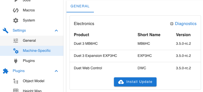
If it doesn't show there, send
M122to check mainboard firmware version, andM122 B1,M122 B2andM122 B3to check status of each expansion board.The expansion boards must be on the same firmware version as the mainboard.
Ian
Bed-slinger - Mini5+ WiFi/1LC | RRP Fisher v1 - D2 WiFi | Polargraph - D2 WiFi | TronXY X5S - 6HC/Roto | CNC router - 6HC | Tractus3D T1250 - D2 Eth
-
Only seeing B0 = 6XD, B1 = 3HC (CAN ID= 1) but not seeing B2 or B3 .A few days ago i could see all of them.They can connected fine. I did update all of them 2 weeks ago with same Firmware RRF 3.4.6
 .
.After updating to 3.5.0-rc.2 i can see all of them but i keep getting an error every minute about " Error: Expansion board 2 stopped sending status"
Error: Expansion board 2 stopped sending status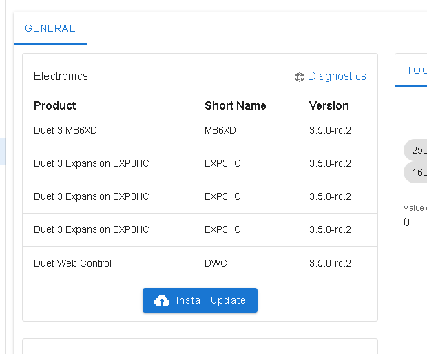
i will check the CAN cables and then reboot everything to see if it continues . After reboot , after a few minutes i started receiving the error again. Then i tried M122 B2 and i get
M122 B2
CAN response timeout: board 2, req type 6024, RID 91