Connecting TMC2208 to Duet2 Wifi CONN_LCD | motors oscillating
-
Hello to all,
I am looking for help with the following problem:
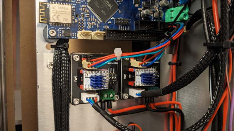
I need two additional stepper motors. One is for pulling a bowden cable to raise/lower the (not)used tool of a dual extruder and one is needed for an exchangeable tool with direct extruder. Therefore I want to connect two TMC2208 to the CONN_LCD header of a Duet2 Wifi. I did this as shown in the following picture:

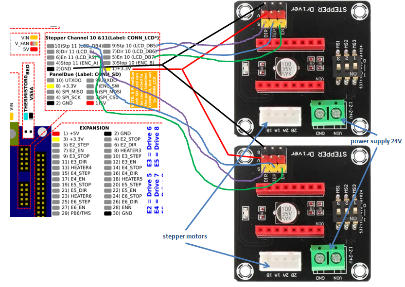
I wired the drivers according to this schematic:

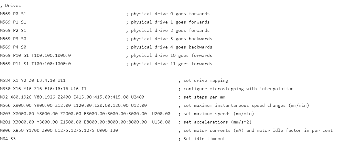
Here screenshots from my config.g file:


When I try to move the motors they oscillate (half a turn or less, they do not only vibrate) but do not move constant in one direction.
Does anyone have an idea what the problem could be? I would be very happy about any tips.
Thanks
Janik
-
@3DKiwi It sounds like the motor current is set too low, so the motor has no power. Have you set the target current for the stepper drivers? You can't set this with M906 for external drivers, so it is usually done by adjusting the trimpot on the top of each driver, and checking the setting by measuring the voltage between the trimpot and ground. There should be some instructions to do this, and target voltage, with the stepper drivers, or on the website where you bought them. I can't tell what drivers they are, but they look similar to this Fysetc one: https://wiki.fysetc.com/TMC2208/
Here's the link to setting the current on those. Note that this depends on various resistors on the stepper driver PCB, and yours might be different! https://wiki.fysetc.com/TMC2208/#motor-current-setting
Ian
-
@3DKiwi ...what droftart said.
The fysetc wiki is a good source for all settings. You might also have to tell the driver, that is in jumper-mode instead of UART-mode. Then you can set microstepping with those microswitches, too. (soldering or cutting traces might be required)
Maybe your stepper driver adapters aren't the best choice. I've used the BTT exp mot v1.0 which has plenty of jumpers to configure "everything" including SPI or UART or jumper mode. -
@o_lampe having a quick look at the image, the switches MS1 to MS3 do the same as the different jumpers under the driver on the BTT-EXP-MOT
-
@jay_s_uk The BTT exp mot has a header with 4x3 pins per driver, while the microswitch only has 3x2.
It's been a while, but IIRC I can only set microsteps with the switches, no com selection. -
Hi,
thank you all for helping!Increasing motor current
I had the reference voltage set to 1V which equals to 1Amp (Peak). I increased it to 1.5V which equals to 1.5A (Peak). Then I tried to move the motors again. The motors vibrated but did not move anymore.When I enable all motors with M17 the motors of x, y and z axis (which are connected to the onboard driver of the Duet) have a lot of torque. The motors connected to the TMC 2208 drivers can still be rotated by hand. It feels like a stick slip effect. But they are not free spinning when enabled.
So just rising the current did not do the trick unfortunately. I just leave it at 1.5Amps until everything works and the motors are connected to the mechanics.
UART vs Standalone mode
The drivers I have look exactly like the fysetc ones. But the shop where I bought them over a year ago does not exist anymore. I know, that they are TMC2208 V1.2 ones. If I understand it correct fysetc wiki says that version 1.2 is in UART mode by default.
Do you know if it is possible to switch the stepper motor driver to standalone/legacy mode? How to do this?Microswitches
The microswitches on the breakoutboard connect the MS1 and MS2 pins to Ground/VIO so they should be there for setting microsteps.Best regards
Janik
-
@3DKiwi said in Connecting TMC2208 to Duet2 Wifi CONN_LCD | motors oscillating:
Do you know if it is possible to switch the stepper motor driver to standalone/legacy mode? How to do this?
According to the fysetc wiki the PDN pin has be on VIO to switch UART off:
PDN UART and Auto Power Down Control: GND=on, VIO=off
I guess you have to cut the trace to GND and solder a wire to VIO.
Not sure what the power down control is all about. I think you aren't able to use some energy-saving features. -
Hi all,
sorry for late reply. Had no spare time the last days to work on the printer.
I tried what @o_lampe suggested. I re-soldered the PDN pin so that it protrudes out of the top of the board and then connected the pin to 3.3V. There was no connection to GND. I measured this via continuity.
Unfortunately, this was also unsuccessful. The mainboard no longer started the WLAN module and I was already afraid that I had broken something. However, after removing the VIO connection to the PDN pin, everything worked again.For no good reason, I then bridged the three solder pads on the underside of the board and soldered the PDN pin the right way round again. In this configuration, at least the enable via M17 works correctly.
I will play around a bit more in the coming days. Specially with the parameters of M569. If I find a solution, I will get back to you.
Otherwise, thanks to everyone who has tried to help
