-
@justGuner please provide a photo of your ESP module/wiring.
what happens if, after an emergency reset, you runM552 S1over USB? does it then reconnect?
If it does, can you grab another M122 output? -
@jay_s_uk After sending M552 S1, it finally connected. Here is the output:
SENDING:M122 === Diagnostics === RepRapFirmware for STM32F4 based Boards (biquskr_2) version 3.5.0-rc.1+102 (2023-09-05 23:19:17) running on STM32F4 (standalone mode) Board ID: A1083-0D0JA-DDPV0-7L182-YB2T9-40000 Used output buffers: 1 of 40 (15 max) === RTOS === Static ram: 19704 Dynamic ram: 89268 of which 156 recycled Never used RAM 20916, free system stack 169 words CCMRam static ram: 24276 dynamic ram: 30348 free ram 10908 Tasks: NETWORK(1,ready,8.0%,243) HEAT(3,nWait,0.0%,365) Move(4,nWait,0.0%,359) TMC22xx(4,nWait,1.8%,146) FSWRITE(2,nWait,0.0%,566) MAIN(1,running,89.1%,563) IDLE(0,ready,1.2%,29), total 100.0% Owned mutexes: WiFi(NETWORK) BITIO(TMC22xx) USB(MAIN) === Platform === Last reset 00:01:05 ago, cause: software Last software reset at 2024-01-29 17:08, reason: User, Gcodes spinning, available RAM 20916, slot 1 Software reset code 0x0003 HFSR 0x00000000 CFSR 0x00000000 ICSR 0x00400000 BFAR 0xe000ed38 SP 0x00000000 Task MAIN Freestk 0 n/a Error status: 0x00 Error status: 0x00 MCU temperature: min 39.6, current 40.0, max 40.1 Supply voltage: min 24.0, current 24.0, max 24.0, under voltage events: 0, over voltage events: 0, power good: yes Heap OK, handles allocated/used 0/0, heap memory allocated/used/recyclable 0/0/0, gc cycles 0 Events: 0 queued, 0 completed Driver 0: standstill 2209, SG min 0, reads 4620, writes 11 Driver 1: standstill 2209, SG min 0, reads 4620, writes 11 Driver 2: standstill 2209, SG min 0, reads 4620, writes 11 Driver 3: standstill 2209, SG min 0, reads 4620, writes 11 Driver 4: standstill 2209, SG min 0, reads 4619, writes 11 Driver 5: Driver 6: Driver 7: Driver 8: Driver 9: Driver 10: Driver 11: Driver 12: Driver 13: Date/time: 2024-01-29 17:09:17 Slowest loop: 99.78ms; fastest: 0.12ms === Storage === Free file entries: 20 SD card 0 detected SD card longest read time 1.5ms, write time 0.0ms, max retries 0 === Move === DMs created 83, segments created 0, maxWait 0ms, bed compensation in use: none, height map offset 0.000, ebfmin 0.00, ebfmax 0.00 no step interrupt scheduled Moves shaped first try 0, on retry 0, too short 0, wrong shape 0, maybepossible 0 === DDARing 0 === Scheduled moves 0, completed 0, hiccups 0, stepErrors 0, LaErrors 0, Underruns [0, 0, 0], CDDA state -1 === DDARing 1 === Scheduled moves 0, completed 0, hiccups 0, stepErrors 0, LaErrors 0, Underruns [0, 0, 0], CDDA state -1 === Heat === Bed heaters 0 -1 -1 -1, chamber heaters -1 -1 -1 -1, ordering errs 0 Heater 1 is on, I-accum = 0.0 === GCodes === Movement locks held by null, null HTTP is idle in state(s) 0 File is idle in state(s) 0 USB is ready with "M122" in state(s) 0 Aux is idle in state(s) 0 Trigger is idle in state(s) 0 Queue is idle in state(s) 0 LCD is idle in state(s) 0 Daemon is idle in state(s) 0 Autopause is idle in state(s) 0 File2 is idle in state(s) 0 Queue2 is idle in state(s) 0 Q0 segments left 0, axes/extruders owned 0x0004003 Code queue 0 is empty Q1 segments left 0, axes/extruders owned 0x0000000 Code queue 1 is empty === CAN === Disabled Longest wait 0ms for reply type 0, peak Tx sync delay 0 free buffers 0 (min 0), ts 0/0/0 Tx timeouts 0,0,0,0,0,0 === Network === Slowest loop: 14.75ms; fastest: 0.00ms Responder states: MQTT(0) HTTP(0) HTTP(0) HTTP(0) HTTP(0) FTP(0) HTTP sessions: 1 of 8 Uploads/Errors: 0/0 === WiFi === Interface state: active Module is connected to access point Failed messages: pending 0, notrdy 0, noresp 0 Bad header: 0/0 Firmware version 1.27-02S-D MAC address 68:58:11:44:3b:b0 Module reset reason: Turned on by main processor, Vcc 3.26, flash size 4194304, free heap 35696 WiFi IP address 192.168.1.40 Signal strength -56dBm, channel 0, mode 802.11n, reconnections 0 Clock register 00004002 Socket states: 0 0 0 0 0 0 0 0 -
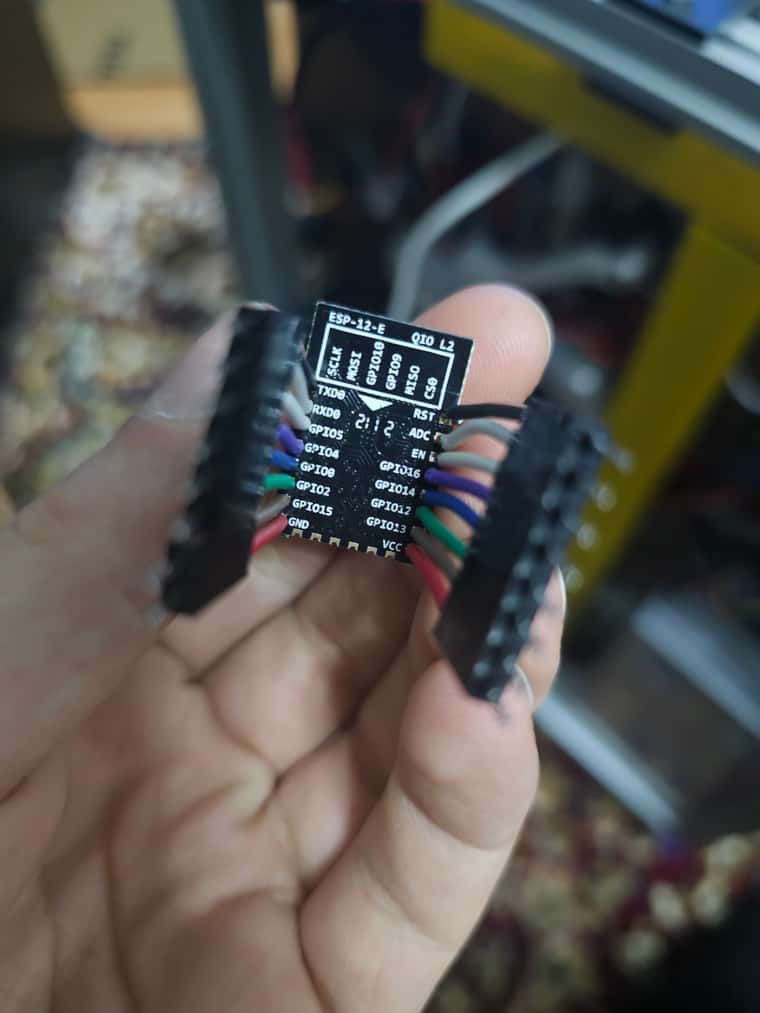
@justGuner Can i ask again for a photo of the ESP/wiring please?
And can you also send the following commands over USB and post the full output
M111 P14 S1
M552 S-1
M552 S1
Give 10 seconds or so between sending each of the above commands
-
@jay_s_uk
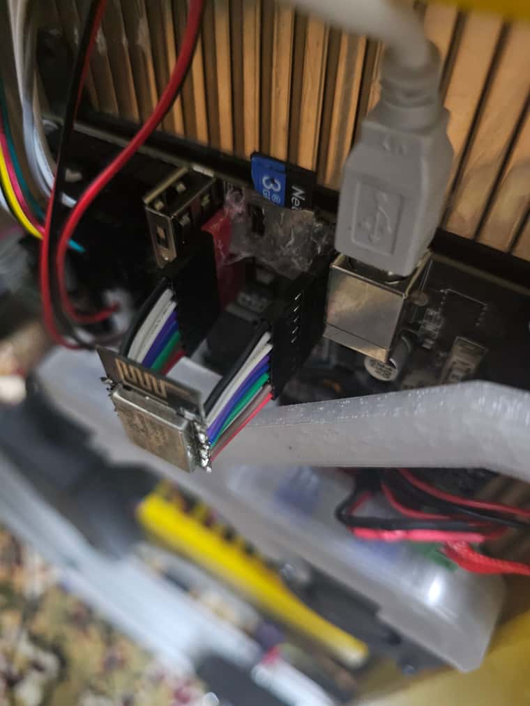
(ignore the hot glue; I ripped the sd card slot accidentally a while back)Here's the output :
s1
SENDING:M552 S1
WiFi:
WiFi:  ets Jan  8 2013,rst cause:2, boot mode:(3,7)
WiFi:
WiFi: load 0x4010f000, len 1392, room 16
WiFi: tail 0
WiFi: chksum 0xd0
WiFi: csum 0xd0
WiFi: v00000000
WiFi: ~ld
WiFi: phy buf[107] is ff adc mode is ff
WiFi: boot not set
WiFi: ota1 not set
WiFi: ota2 not set
WiFi: V2
WiFi: Mo
WiFi: irf cal sector: 1019
WiFi: freq trace enable 0
Got rubbish reply from COM5 at baudrate 115200:
Maybe a bad baudrate?
I did try the same command with other baudrates; it gave the same rubbish reply thing every time
-
@justGuner What are you using to connect to the board? If you are using a Windows PC I would suggest using putty see: https://teamgloomy.github.io/putty.html We really need to see all of the output to work out what is happening. If you are connecting to the board via USB the baud rate is ignored.
I've not seen a module connected like that before. You seem to have a lot more pins connected between the module and the board than we would normally recommend (Our setup uses 11 in total I think you have 16 connected). I'm not sure if the additional ones could be causing a problem.
-
@gloomyandy yeah, I'm not gonna be able to try new things for about a week since I won't be near the printer...
I am connected to the printer over USB via pronterface
In terms of the pins used, I assumed that because on the official esp board there are 16 pins, all of them are connected. What are the necessary pins (on the esp) for the module to work properly?
-
@justGuner We don't have instructions for that board because most people simply use a commercially available module (if you get one get an esp32). The module you linked to may have all of the pins but I suspect some of them are not connected. You may be able to work out the connections from looking at the details of the homemade boards for the SKR Pro and mathcing it up with the skr 2 schematic. https://teamgloomy.github.io/skr_pro_connected_wifi_8266.html note that this does not include the UART connections, but I think you already have those working correctly.
I'd strongly recommend using putty rather than pronterface. Pronterface tends to try and interpret/change the commands and responses and generally "gets in the way".
-
 undefined dc42 moved this topic from General Discussion
-
Here is a little update on the situation: after trying to solder some resistors to the esp according to this, I think I managed to damage the esp somehow, because after connecting it to the skr afterwards resulted in timeout errors no matter what. To make sure, I reverted to the previous method of wiring straight to the wifi header just like before, only to result in the same timeout error.
If I'm unable to fix this new issue by trying to resolder the wires again, I think I will just buy the btt esp module.
-
@justGuner I think all of the resistors that are needed are already on the skr2 board (see the schematic I linked to above). If you do get a module I'd strongly recommend that you get an esp32 version not an esp8266. Not sure if BTT do a esp32 but, Fly/Mellow certainly does. You will get much better performance from that and additional features.
-
@gloomyandy can you tell me what are some of the other features I get by going with the esp32? All I could find online was improved conectivity over the 8266
-
-
@deckingman Yeah but how many of those features can I use on the 3d printer itsels? For example as far as I know there isn't any bluetooth suport in rrf yet, and the sole reasong for buying an esp is to be attached to the printer, so I'm not thinking about using it in other projects
-
@justGuner The main "feature" is the improved upload speed. With the esp8266 the best I ever see is around 550KBytes/s with the esp32 I see up to 2.5MBytes/s with a STM32H7 based board, with a STM32F4 board I'd expect around 1.8MBytes/s. But that all depends on your WiFi signal SD card speed etc.
The other thing is that new features like enterprise wifi authentication and the MQTT support both need the latest 2.1 version of the WiFi firmware and that seems to run much better on the esp32. Basically there is not likely to be any new work on the esp8266 firmware going forwards (at least not from me). For the small extra cost I just don't think it makes sense to use an 8266.
-
I finally installed a esp32 from btt and it works just fine. Too bad I couldn't find an answer for the original question that started this thread. I might revisit this at some point in the future, who knows...