Clarifying BigTree Filament Sensor Connection.
-
I got a BigTree Filament sensor v1 in a clearance sale. I finally got around to connecting it after making modifications to my custom printer to mount it. There are other articles on this forum and elsewhere about. I'm going to summarize what I know before I ask my question.
The BigTree sensor is a pulse sensor using holes in a wheel that turns with filament movement and this turning is sensed optically. Elsewhere you can find people figuring out the electronics. The unit (as stock) is apparently capable of quadrature (that is: sensing direction as well as distance. I don't know how to connect that bit). The sensor creates one pulse every 7 mm. An example config line is:
M591 D0 P7 C"e0stop" L7 R75:125 E22 S1
which means:
- M591: configure a filament sensor
- D0: on extruder 0
- P7: of type pulse
- C"e0stop": on the pins for e0stop
- R75:125: with a sensitivity of 25% of requested length
- E22: sampled every 22mm
- S1: enabled for SDCard prints
Now... the 4 pin header on the unit is (from nearer the business end to further):
- Ground
- Signal A
- Signal B
- Vss
... where the provided cable only connects Signal A. I think comparing A to B is the quadrature.
The connector on the duet 2 (e0 or e1) is:
- Stop
- V3.3
- Gnd
Now... I think that I erroneously connected signal to V3.3 for some time (hours).
Is this board dead from that? I'm not getting signal. Can I order parts and fix? Is my config incorrect? Let's put a bow on this for the future.
-
@zBeeble What version of RRF are you running? Send M115 in the console and post the response. What does sending
M591 D0respond with? Note that you have M591 ... S1 set, so filament monitoring is only active when printing from the SD card. If you are using RRF 3.5.0-rc.1 or later, you can set S2, and filament monitoring is active all the time.Connecting 3.3V to the Duet endstop shouldn't be a problem; the STP pins are 8V-tolerant on revision 1.04 boards and later. Earlier boards are, I think, at the very least 3.3V tolerant. If you're not sure, test the endstop pin with a microswitch between GND and STP pins, and see if it responds correctly when configured as an endstop.
To test the filament sensor, try wiring it to the e1stop. Could be it's the filament sensor that is faulty, rather than the Duet.
Ian
Bed-slinger - Mini5+ WiFi/1LC | RRP Fisher v1 - D2 WiFi | Polargraph - D2 WiFi | TronXY X5S - 6HC/Roto | CNC router - 6HC | Tractus3D T1250 - D2 Eth
-
M115 says this:
m115
FIRMWARE_NAME: RepRapFirmware for Duet 2 WiFi/Ethernet FIRMWARE_VERSION: 3.4.5 ELECTRONICS: Duet WiFi 1.02 or later FIRMWARE_DATE: 2022-11-30 19:36:12
And M591 d0:
m591 d0
Pulse-type filament monitor on pin e1stop, enabled, sensitivity 7.000mm/pulse, allowed movement 0% to 125%, check every 22.0mm, no data received
I've set the config to have a lower bound of 0 for this test. Effectively not stopping. This reading was taken after 200mm of extrusion.
-
Check your wiring, there are some incorrect and / or confusing diagrams on the internet. There actually may have been more than one build ..

https://www.youtube.com/watch?v=7xVRTtWErvoHere is what mine looks like (excuse the hot glue - long story involving a lost cable).
Red = V+
Space
White = Signal in
Black = Gnd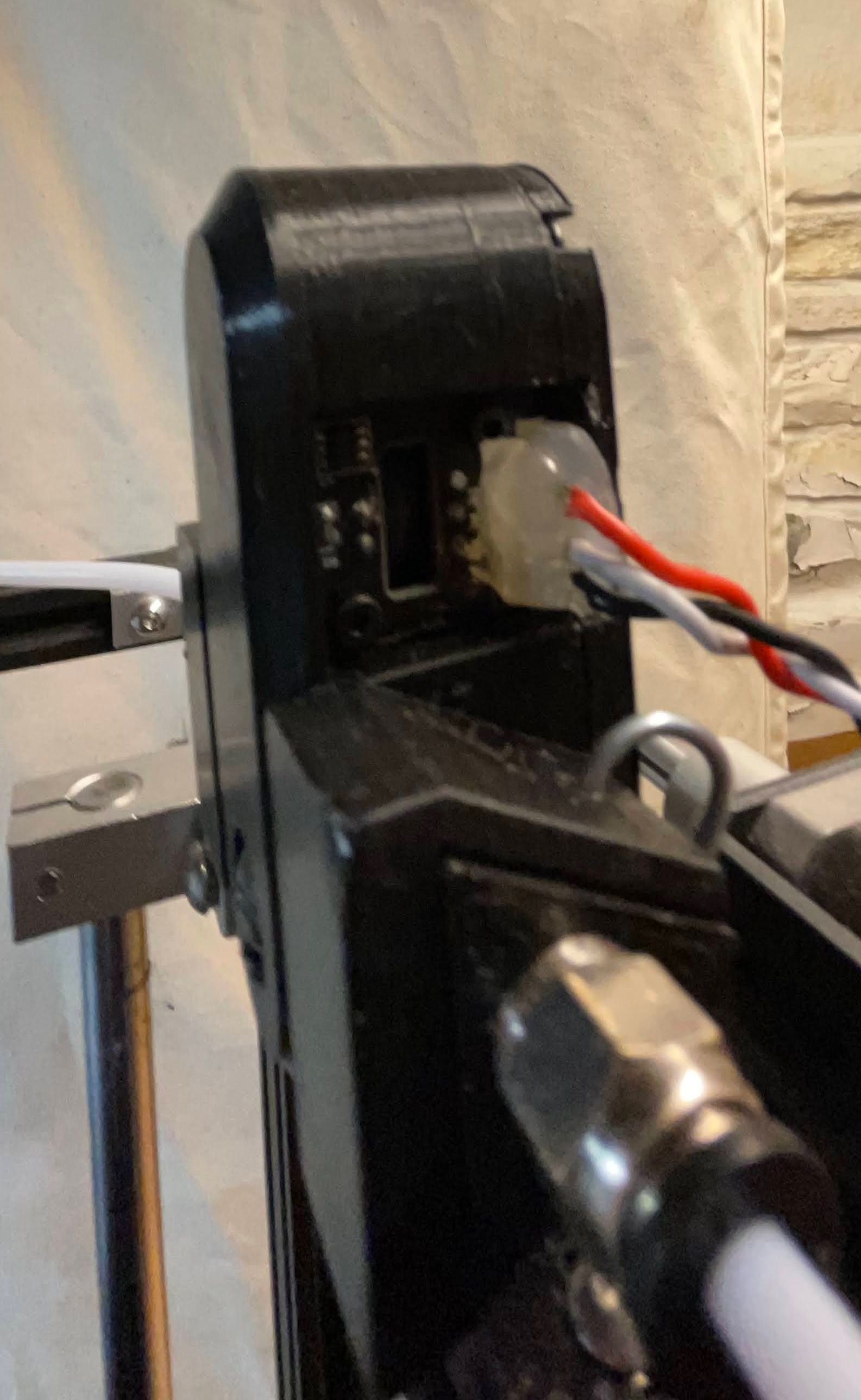
-
@stuartofmt This, based on the filament position w.r.t. the header, agrees with what I have been referencing.
If I had V and GND swapped, would that kill the BigTree? What do you guys who understand the circuit diagram expect?
I did also try the e1stop --- no change there.
-
@zBeeble said in Clarifying BigTree Filament Sensor Connection.:
@stuartofmt This, based on the filament position w.r.t. the header, agrees with what I have been referencing.
If I had V and GND swapped, would that kill the BigTree? What do you guys who understand the circuit diagram expect?
I did also try the e1stop --- no change there.
15 seconds into the video. Maybe.