delta head going beyond bed limits 3.5.1
-
3.5.1, recent bookworm DuetPi, delta
I've just found that it lets me move beyond the bed limits. It's a delta, 150mm radius. I can
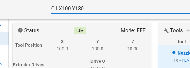
G1 X100 Y130(which is 164mm radius) and it will go there:

Not only does the web page say it is there, it really is there - nozzle is outside the bed.But it won't move away from there, because "intermediate position outside machine limits". At this point all I can do is home.

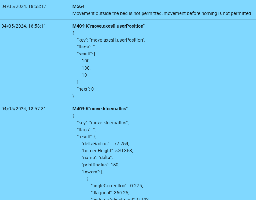
M564 says movement is not allowed outside bed, but the head is outside the bed, and the kinematics is definitely set to 150 print radius:

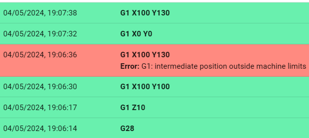
However, it won't go outside the bed from all positions. If I
G1 X100 Y100first, then it won'tG1 X100 Y130. However, if I return toG1 X0 Y0and then go direct toG1 X100 Y130it will happily go there:
 .
.It will also go outside the bed using the move buttons on the PanelDue and on the web page.
Duet 3 MB6HC 3.5.1
Duet 3 Expansion TOOL1LC 3.5.1
Duet Software Framework DSF 3.5.1
Duet Web Control DWC 3.5.1
SBC (Pi4) bookworm DuetPiconfig.g
; Configuration file for Duet 3 (firmware version 3) ; initially generated by RepRapFirmware Configuration Tool v3.1.4 on Thu Sep 17 2020 20:49:45 ; but subsequently significantly modified variously ; this for firmware 3.5.1 ; initial pause for power and CAN bus to stabilise G4 S2 ; General preferences M550 P"Delta" ; set printer name G90 ; send absolute coordinates M83 ; relative extruder moves ; geometrical config ; M665 = diagonal rod length, delta radius, homed height, printable radius, tower pos corrections ; M665 L360.250:360.250:360.250 R184.819 H538.341 B150.0 X-0.227 Y0.223 Z0.000 ; old 55mm centres effector M665 L360.250:360.250:360.250 R177.754 H520.261 B150.0 X-0.166 Y0.337 Z0.000 ; new 80mm centres effector M666 X0.101 Y0.027 Z-0.128 A0.00 B0.00 ; endstop adjustments ; Drives M569 P0.0 S0 ; physical drive 0.0 goes backwards M569 P0.1 S0 ; physical drive 0.1 goes backwards M569 P0.2 S0 ; physical drive 0.2 goes backwards M569 P121.0 S0 ; toolboard (CAN 121) drive 0 goes backwards M584 X0.0 Y0.1 Z0.2 E121.0 ; set drive to axis mapping M350 X16 Y16 Z16 E16 I1 ; configure microstepping with interpolation M92 X160.00 Y160.00 Z160.00 E680.00 ; set steps per mm - note XYZ are 400 steps/rev motors ; note extruder steps should notionally be 690 - to be tested (680 is figure from bear) ;M592 D0 A0.0007 B0.0010 ; configure non-linear extrusion, tbc with new extruder ; Speeds ; jerk at configtool defaults (20 mm/s) but extruder at manuf recommended values M566 X1200.00 Y1200.00 Z1200.00 E300.00 ; set maximum instantaneous speed changes (mm/min) ; max axis motor speed - duet apparent max step rate 145kHz, ; 145kHz at 160 steps/mm = 906 mm/s ; carriages run at 2.5x print head (at extreme position, rods at approx 22 deg) ; thus print head speed = 906/2.5 = 362 mm/s = 21750 mm/min ; However, back EMF for this is too high ; use RRF back-EMF calculator and keep either value < 24V, and sum < 36V ; so supply voltage is at least 2/3 of theoretical combined value ; this is satisfied if max speed = 250 mm/s - gives 12.1V and 23.6V ; 250 mm/s = 15000 mm/min ; extrude motor speed limit ; 145kHz at 690 steps/mm = 210 mm/s = 12,609 mm/min ; but use manufacturer recommended 7200 mm/min M203 X15000 Y15000 Z15000 E7200 ; set maximum speeds (mm/min) ; acceleration (configtool default is 1000 mm/s2) and set extruder to manuf recommended M201 X1200 Y1200 Z1200 E3000 ; set accelerations (mm/s^2) ; rated current E3D high-torque motor = 1.68A, x 75% = 1260 mA ; however, motors stay quite cool at that current ; increase current to 85% = 1430 mA ; extruder manufacturer recommended current is 1200 and idle 10%, but cannot set idle per axis M906 X1430 Y1430 Z1430 E1000 I30 ; set motor currents (mA) and motor idle percentage M84 S60 ; Stop idle hold after 60 seconds timeout ; Enable on-board accelerometer on the toolboard and/or apply input shaping ;M955 P121.0 I54 M593 P"zvdd" F37 ; Axis Limits M208 Z0 S1 ; set minimum Z ; Endstops M574 X2 S1 P"io6.in" ; configure active-high endstop for high end on X via pin io0.in M574 Y2 S1 P"io1.in" ; configure active-high endstop for high end on Y via pin io1.in M574 Z2 S1 P"io2.in" ; configure active-high endstop for high end on Z via pin io2.in ; Z-Probe on CAN bus 121 ; note cannot program smart effector via toolboard, so no out port defined M558 P8 R0.4 C"121.io0.in" H3 F1200 T6000 ; set Z probe type to effector via toolboard and the dive height + speeds G31 P100 X0 Y0 Z-0.12 ; set Z probe trigger value, offset and trigger height M557 R145 S64 ; define mesh grid ; Heaters ; bed M308 S0 P"spi.cs1" A"bed" Y"rtd-max31865" ; configure sensor 0 as PT100 via CS pin spi.cs1 M950 H0 C"out1" Q3 T0 ; create bed heater output on out1 and map it to sensor 0 ; v3.1 tuning: M307 H0 A530 C1330 D21 S1 V0 B0 M307 H0 R0.243 C1212.7 D46.41 S1.0 V0 B0 ; configure bed heater average three runs of M303 H0 S75 M140 H0 S0 ; map heated bed to heater 0 M143 H0 S150 ; set temperature limit for heater 0 to 150C - fault at 150 ; hotend ; previous: M308 S1 P"spi.cs0" Y"rtd-max31865" A"hotend" ; hotend was previously PT100 via CS pin spi.cs0 M308 S1 P"121.temp0" A"hotend" Y"thermistor" T100000 B4725 C7.06e-8 ; E3D Revo built-in thermistor M950 H1 C"121.out0" Q25 T1 ; create nozzle heater output on toolboard out0 and map it to sensor 1 ; v3.1 tuning: M307 H1 A550 C330 D3 S1 V24 B0 ; v3.2 tuning: M307 H1 R1.543 C300:200 D4.17 S1.0 V24 B0 ; average of three runs M303 H1 S220 ; v3.3 tuning after rebuilding and rewiring effector: M307 H1 B0 R1.642 C245.2:183.2 D4.36 S1.00 V23.9 ; v3.4 tuning with E3D revo micro: M307 H1 R4.4 K0.47 D1.48 E1.35 S1.00 B0 V24 ; v3.5 tuning with revo via toolboard and diodes in supply: M307 H1 R3.90 K0.48:0.85 D1.95 E1.35 S1.00 B0 V24.0 ; average of multiple runs - see spreadsheet M143 H1 S300 ; heater 1 limit 300 (generate heater fault) ; chamber M308 S2 P"temp3" A"chamber" Y"thermistor" T4701 B4266 C1.048787e-7 ; dangling thermistor M950 H2 C"out3" T2 ; create a heater, but not actually anything connected to this output M141 H2 S99 ; set this to be chamber and set initial temperature (99 is effectively a flag) M141 S-400 ; switch chmaber heater off ; additional temperature sensors ; sensor 3: thermistor in bed heater mat M308 S3 P"temp2" A"bed_mat" Y"thermistor" T100000 B3950 ; use this as additional overtemperature M143 H0 S150 P1 T3 A2 ; turn off heater if mat gets to 150C ; 4,5,6 - toolboard information ; sensor 4: PT1000 just above alu plate M308 S4 A"tool air" Y"PT1000" P"121.temp1" ; sensor 5: mcu temperature sensor M308 S5 A"tool processor" Y"mcu-temp" P"121.dummy" ; sensor 6: overtemperature flag on stepper driver M308 S6 A"tool drivers" Y"drivers" P"121.dummy" ; 7,8,9 mainboard information ; sensor 7: thermistor in electronics enclosure M308 S7 P"temp0" A"6HC air" Y"thermistor" T4701 B4266 C1.048787e-7 ; sensor 8: mcu temperature sensor M308 S8 A"6HC processor" Y"mcu-temp" ; sensor 9: overtemperature flag on stepper drivers M308 S9 A"6HC drivers" Y"drivers" ; Fans ; print fan is four-wire on toolboard out1 M950 F0 C"!121.out1+out1.tach" Q25000 ; create fan 0 on toolboard out1 and set its frequency M106 P0 S0 L0.1 B0.5 H-1 C"print" ; fan initially off, min pwm 0.1, 0.5 second blip, not thermostatic ; hot end fan ; hot end fan is always either on or off so PWM frequency etc. don't much matter M950 F1 C"121.out2" Q100 ; create fan 1 on toolboard out2 and set its frequency M106 P1 S1 H1 T50 C"hotend" ; set fan 1 thermostatic control on heater 1 at 50C ; other cooling fans ; both following predominantly controlled by analogue sensors but also set if stepper drivers flag is set ; fan 2 is blowing air into electronics compartment M950 F2 C"!out4" Q25000 ; fan 2 is 4-wire noctua on out4 (note inverse for 4-wire to work correctly) tacho not used M106 P2 S1 L0.25 B0.2 H7:9 T35:40 C"mainb" ; cooling electronics space thermostatic on sensor 7 35 to 40C ; fan 3 is small centrifugal fan blowing under main board M950 F3 C"out9" Q100 ; fan 3 on pin out9 and set its frequency M106 P3 S1 L0.4 B0.5 H8:9 T50:60 C"underb" ; fan 3 for cooling mainboard underside thermostatic sensor 8 (mcu temperature) 50 to 60C ; fan 4 is enclosure purge fan ; initially this is hard-coded to start at 35C enclosure temperature ; but daemon.g will override it M950 F4 C"!out5" Q25000 ; fan 4 is 4-wire noctua on out5 (note inverse for 4-wire to work correctly) tacho not used - could be '+out5.tach' M106 P4 S1 L0.25 B0.2 H2 T36:40 C"chamber" ; fan 4 thermsotatic, narrow band ; other IO etc ; paneldue on io0 M575 P1 S1 B57600 ; serial channel 1, PanelDue mode w checksum; 57600 baud ; filament monitoring M591 D0 P1 C"121.io1.in" S1 ; enable filament monitoring on toolboard io1, high = filament present M950 J2 C"121.io2.in" ; filament sensor press-button is on different IO set to sensor 2 M581 P2 T2 S1 R2 ; set up trigger 2 on the press-button (extrudes) if !exists(global.t2time) global t2time = state.upTime ; used to memorise nozzle temperature else set global.t2time = state.upTime ; toolboard buttons M950 J3 C"121.button0" ; corner button defined as sensor 3 M581 P3 T3 S1 R2 ; calls trigger 3 when pressed (when not printing) ; servo 1 on io7.out (note, needs to be 4, 5 or 7 as these are only PWM capable outputs) M950 S1 C"io7.out" ; create servo 1 M280 P1 S10 ; set to 10 degree position, which is blades closed ; GPIO P2 used to reset attached pi M950 P2 C"io4.out" Q10 ; gpio 2 set to 10Hz on io4 M42 P2 S1 ; that gpio set high ; M42 P2 S0 will shut down pi via. GPIO header ; 24V power control (only enabled for drives and heaters) ; note toolboard gets power from either 12V or 24V (diodes) M81 C"pson" ; set up power pin, power off ; system to memorise settings and filament parameters if !exists(global.nozt) global nozt = -1 ; used to memorise nozzle temperature when pausing if !exists(global.filament) global filament = "" ; this will be name of filament if !exists(global.filChangeT) global filChangeT = 0 ; this will be the nozzle temperature for a filament change if !exists(global.filWeight) global filWeight = 0 ; this will be teh weight of filament on spool M98 P"0:/sys/setfilament.g" ; enable whatever was last recorded ; Define tool M563 P0 S"Nozzle" D0 H1 F0 ; define tool 0 G10 P0 X0 Y0 Z0 ; set tool 0 axis offsets G10 P0 R0 S0 ; set initial tool 0 active and standby temperatures to 0C M207 S1.5 F7200 Z0.2 ; set typical retract T0 ; select first tool -
 undefined Phaedrux marked this topic as a question
-
 undefined Phaedrux moved this topic from General Discussion
-
Can you confirm that reverting to an older firmware doesn't have the same issue?
-
@Phaedrux said in delta head going beyond bed limits 3.5.1:
Can you confirm that reverting to an older firmware doesn't have the same issue?
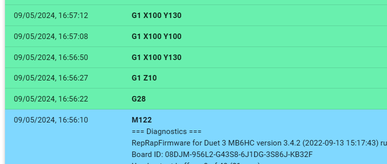
I've reverted to 3.4.2 (that version becasue I have a flash card with that on it) and it also will go outside the bed, though it will come back inside the bed and then go out again:

However, I note that @chrishamm has separately diagnosed that I have an issue where something in the config prevents the move key in the object model from being properly refreshed (https://forum.duet3d.com/post/338869) it seems to me that that and this are potentially related issues, and it's probably sensible to wait for the fix of that before investing more effort in this.
Edit: I've said park it, but for reference when returning to this: I've also determined the printer will try and move to positions with Z higher than it can reach - at X0 Y150 my max Z achievable is about 470, but it will try and motor to higher than that (running the carriage into the endstop and making the motor skip).
-
@achrn Until I read about the z-problem I thought the simple solution was to define the print radius in the slicer software.
No parts wider than the print radius would be allowed. End of story...
But I guess, the slicer only checks the radius and doesn't know about the dome shaped print envelope at the top.Now I want to know: what was the last RRF version which actually kept the motors from bumping into the endstops?
-
@o_lampe Yes, slicer has the print radius defined so the slicer never sends the printhead to where it shouldn't be (in plan) but it doesn't know about the funny shape at the top of the printable envelope.
What happened was that I changed the arrangement of the umbilical to the effector, so was testing the head at the limits of travel with the movement buttons (in both web interface and on PanelDue) to make sure it didn't snag on carriages, and while manually driving it around watching the umbilical more than the head to try and provoke it to snag, I discovered I had moved the head beyond the print bed. If I hadn't been doing that, I wouldn't have discovered it.
Similarly, I don't generally try and go higher than it can reach - I remember occasions in the past when setting up filament change and pause.g and similar files that the printer has on occasion complained about cannot reach a point, but as to which version it was, I have no idea. Also, it does now sometimes complain about cannot reach a point still, but I haven't figured out what makes it decide to try or not.
-
@achrn Thanks for reporting this. I have tested and got the same results. I've raised an issue on Github for @dc42 to track progress on fixing this issue: https://github.com/Duet3D/RepRapFirmware/issues/997
I didn't test how far back this is a problem. Odd not to have spotted it before!
Ian
-
@droftarts said in delta head going beyond bed limits 3.5.1:
Odd not to have spotted it before!
In my case, it is because I rarely print such tall objects. And if I do, they are airfoils with a narrow tip.
It would've been more obvious, if mesh probing wouldn't do it right. But this algorithm seems to work properly.
Even with a probe offset of 18mm in Y, like I have. -
@o_lampe my test was at Z10, as was that done by @achrn. It's not the shape at the top we are concerned with here, it’s that it goes beyond M665 B parameter.
The cone at the top is limited by the endstop switches, so I’m pretty sure the firmware takes account of that, though I didn’t test that. It’s why you always have to move down in Z after homing, before moving in X and Y.okay, rereading @achrn’s post, it’s trying to go outside the cone at the top too. I’ll update the issue on GitHub.Ian