BL Touch Deploying but Always Triggered
-
My BL Touch deploys correctly upon turning on my machine but doesn't respond to M401 or M402. The Z-Probe signal in my DWC seems to always show it as triggered so when I try to test dynamically it ofc triggers immediately. I seem to have it wired correctly so I believe something in my config.g is wrong. Just looking for a second set of eyes to see if anything sticks out in my config.g or where else to look. Thanks in advance!
; Enable network G4 S5 ;wait for board to start if {network.interfaces[0].type = "ethernet"} M552 P192.168.1.14 S1 else M552 S1 ;General Prefrences G90 ;send absolute coordinates... M83 ;...but relative extruder moves M586 P0 S1 ; enable HTTP M586 P1 S0 ; disable FTP M586 P2 S1 ; enable Telnet M586 C"*" M550 P"RL1 V3" ;set printer name M669 K1 ;switch to CoreXY mode ; Drives M569 P0.0 S1 ;X motor runs M569 P0.1 S0 ;Y motor runs M569 P0.2 S1 ;Z1 motor runs M569 P0.4 S1 ;Z2 motor runs M569 P0.5 S1 ;Z3 motor runs M569 P50.0 S0 ;E moves M569 P0.3 S0 ;U motor runs M569 P50.1 S1 ;V motor runs (front clamp driver) M569 P50.2 S1 ;W motor runs (back clamp driver) M207 S1.5 F7200 Z0.2 ;set retract length M584 X0.0 Y0.1 Z0.2:0.4:0.5 E50.0 U0.3 V50.1 W50.2 ;Set drive mapping M350 X16 Y16 Z16 E16 U16 V16 W16 I1 ;configure microstepping with interpolation M92 X80.00 Y80.00 Z400.00 E685.37234 U100 V80 W80 ;set steps per mm M566 X900.00 Y900.00 Z60.00 E300 U900.00 V900 W900 ;set maximum instantaneous speed changes (mm/min) M203 X6000.00 Y6000.00 Z180.00 E7200 U17000.0 V6000 W6000 ;set maximum speeds (mm/min) M201 X500.00 Y500.00 Z20.00 E3000 U500.0 V500 W500 ;set accelerations (mm/s^2) M906 X800 Y800 Z800 E1200 U3800 V800 W800 I30 ;set motor currents (mA) and motor idle factor in per cent M84 S30 ;Set idle timeout ; Axis Limits M208 X0 Y0 Z-1 U0 V0 W0 S1 ;set axis minima M208 X100 Y100 Z38.45 U330 V55 W55 S0 ;set axis maxima ; Endstops M574 X1 S1 P"0.io8.in" ;configure switch-type (e.g. microswitch) endstop for low end on X via pin io0.in M574 Y2 S1 P"0.io7.in" ;configure switch-type (e.g. microswitch) endstop for high end on Y via pin io1.in M574 Z2 S1 P"0.io2.in+0.io1.in+0.io5.in" ;configure switch-type (e.g. microswitch) endstop for high end on Z M574 U2 S1 P"0.io6.in" ;configure switch-type (e.g. microwswitch) endstop for high end on U M574 V1 S1 P"50.io6.in" ;configure switch-type end stop for low end on V M574 W1 S1 P"50.io5.in" ;configure switch-type end stop for low end on W ; Z-Probe M950 S0 C"0.io4.out" ; create servo pin 0 for BLTouch (use IO_4/5/7 for 6HC) M558 P9 C"0.io4.in" F100 H5 R0.2 T6000 A5 B1 ; set Z probe type to bltouch and the dive height + speeds G31 P25 X-19.14 Y0 Z4.242 ; set Z probe trigger value, offset and trigger height M557 X0:80 Y12:100 P3 ; define mesh grid ;Heaters M308 S0 P"temp0" Y"thermistor" T100000 B3950 ; configure sensor 0 as thermistor on pin temp0 M950 H0 C"0.out0" T0 ; create bed heater output on out0 and map it to sensor 0 M307 H0 R0.075 K0.161:0.000 D3.07 E1.35 S1.00 B0 M140 H0 ; map heated bed to heater 0 M308 S1 P"50.temp_0" Y"thermistor" ; configure sensor 1 as thermistor on pin temp1 M950 H1 C"50.out0" T1 ; create nozzle heater output on out1 and map it to sensor 1 M307 H1 R4.585 K0.421:0.683 D3.75 E1.35 S1.00 B0 V24.2 ; disable bang-bang mode for heater and set PWM limit M143 H1 S280 ; set temperature limit for heater 1 to 280C ; Fans M950 F0 C"0.out7" Q500 ; create fan 0 on toolboard out1 and set its frequency M106 P0 S0 H-1 T50 ; set fan 0 value. Thermostatic control is turned on M950 F1 C"0.out8" Q500 ; create fan 1 on toolboard out2 and set its frequency M106 P1 S0 H-1 ; set fan 1 value. Thermostatic control is turned off ;Tool Definitions M563 P0 D0 H1 F0 ; tool 0 uses extruder drive 0 and heater 1. Fan 0 and Fan 1 are mapped to tool 0 G10 P0 X0 Y0 Z0 ; set tool 0 axis offsets G10 P0 R0 S0 ; set initial tool 0 active and standby temperatures to 0C ;Misc M950 P3 C"0.out2" Q500 ; allocate port 3 to out2 on MB6HC for Inlet valve M42 P3 S0 ; set to off M950 P4 C"50.out2" Q500 ; allocate port 4 to out2 on Mini5 for IPV Direction M42 P4 S0 ; set to off M950 P5 C"50.out1" Q500 ; allocate port 5 to out1 on Mini5 for Chamber Valve M42 P5 S0 ; set to off M950 P6 C"0.out3" Q500 ; allocate port 6 to out3 on MB6HC for Release Valve M42 P6 S0 ; set to off ; Epilogue M556 S100 X0 Y0 Z0 ; Put your axis compensation here M912 P0 S0 ; Put your CPU temperature sensor correction here M501 ; load saved parameters from non-volatile memory M911 S10 R11 P"M913 X0 Y0 G91 M83 G1 Z3 E-5 F1000" ; set voltage thresholds and actions to run on power loss T0 -
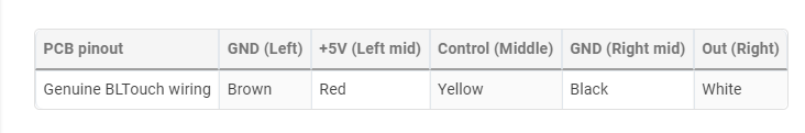
@JRCL If it's a genuine BLTouch, then the yellow wire is usually the servo control wire, and should be on io4.out, while the white wire is the signal wire and should be on io4.in, so yours are the wrong way around. That's how mine is wired, on a 6HC. See https://docs.duet3d.com/en/User_manual/Connecting_hardware/Z_probe_connecting#wiring-the-bltouch
Ian
Bed-slinger - Mini5+ WiFi/1LC | RRP Fisher v1 - D2 WiFi | Polargraph - D2 WiFi | TronXY X5S - 6HC/Roto | CNC router - 6HC | Tractus3D T1250 - D2 Eth
-
I had this happen briefly on an existing system. I reseated the wires and that fixed it.
-
@zBeeble Unfortunately I tried a full rewire and different set of pins before posting this
-
@JRCL said in BL Touch Deploying but Always Triggered:
but doesn't respond to M401 or M402.
it seems like the probe is gone into an error state. Does it do a self test on startup where it reploys and retracts the pin?
Photos of the wiring?
Does it respond to any of the bltouch servo commands?
-
Its also [possible the BLtouch wiring is picking up interference from other wiring that runs parallel to it. If your wiring is nice and neat and bundled together, this could be happening. I had problems with my motor wires in this way. For me, moving the wires around in the bundle so they were not running so close for so far solved it.
-
@Phaedrux yes the self test upon startup is working fine, which is the first time I've seen that working but holding a triggered state in DWC. It is wired like so to my MB6HC:
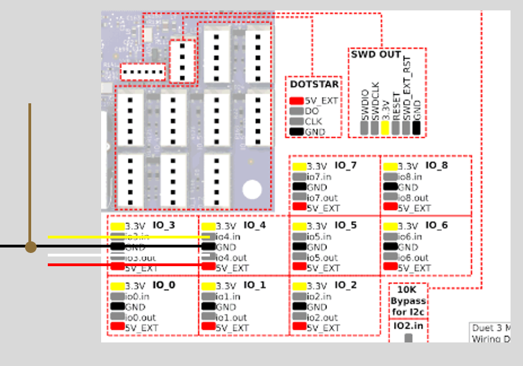
By servo commands do you mean just sending M42 or M280 commands to try and get it to go manually? If so I haven't tried those yet and will give that a go next
-
@mikeabuilder it did live in a cable chain for a while but since troubleshooting and the rewire its been removed and still seems to have the issue
-
@JRCL If it's a genuine BLTouch, then the yellow wire is usually the servo control wire, and should be on io4.out, while the white wire is the signal wire and should be on io4.in, so yours are the wrong way around. That's how mine is wired, on a 6HC. See https://docs.duet3d.com/en/User_manual/Connecting_hardware/Z_probe_connecting#wiring-the-bltouch
Ian
Bed-slinger - Mini5+ WiFi/1LC | RRP Fisher v1 - D2 WiFi | Polargraph - D2 WiFi | TronXY X5S - 6HC/Roto | CNC router - 6HC | Tractus3D T1250 - D2 Eth
-
@droftarts this was what I needed! I had been using the table above that, that says PCB Pinout, but I'm now realizing it's for the BL Touch's pins not the boards. Thanks!
-
 undefined JRCL has marked this topic as solved
-
undefined JRCL has marked this topic as solved