IDEX BOTH ON CORE XY
-
@dwuk I remember now, I've discussed the striped sections before on this forum. Was it you, who came up with it?
It was the same time I started using resin printers and immediately saw their advantages against FDM printing.
Opposite to the rounded corners you get with FDM, the resin-print edges are sharp and easy to glue together.
Unfortunately no multicolor prints, but ~10x smaller surface details possible. Plus: no problem with overhangs. -
@o_lampe Not me as only just joined the forum - but yes I agree that Resin likely to be better with corners as I presume the pixels are effectively square or combinations of them appear to be. I've done quite a lot of investigations into eliminating round corners by adding extract features that need to be shaved off - see here - but in the end for ships it doesn't really matter that much as the real ships usually have lots of visible weld joins on them.
Further improvements made today to
 outer wall isolation and layer by layer resizing of segments here
 -
As suggested by @johannesvannahme8631 on YouTube - have improved my 4 head autoswitch, Mirror and Parallel printing demo a bit.
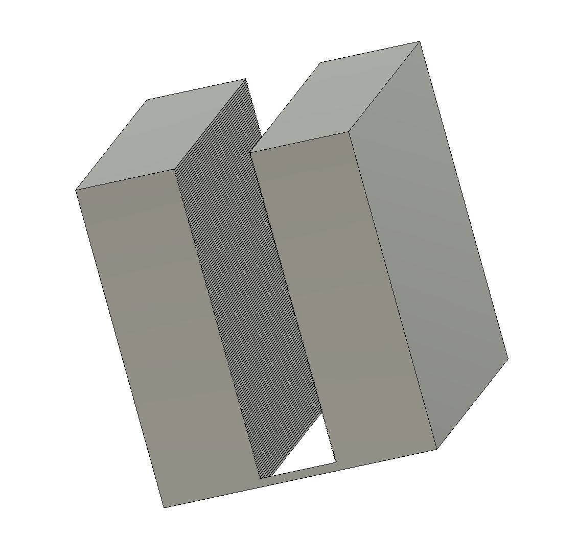
I created some cutter parts with edges that go in an out for added strength using Fusion 360 - that can be used in BambuStudio (or Orca I would imagine) as negative parts to
a). Cut out the middle - that can't be mirrored due to head clashes
b) Cut out just the left hand side to be mirrored.
I then cloned two copies of the benchy in the same place on the build plate - one for the mirrored half - in tool4, and one for the centre part in tool1.
I then applied the appropriate negative cutter part to each clone.
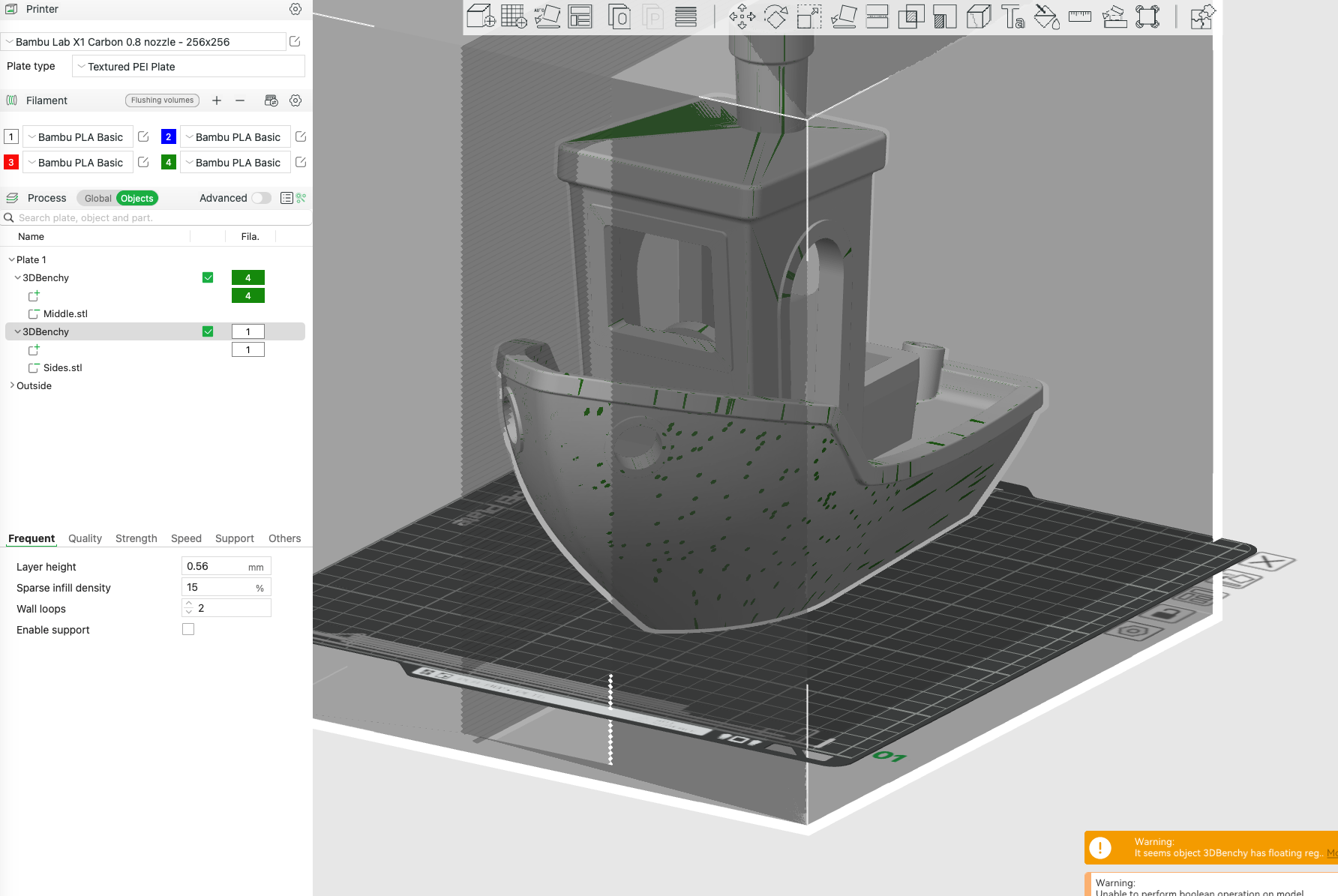
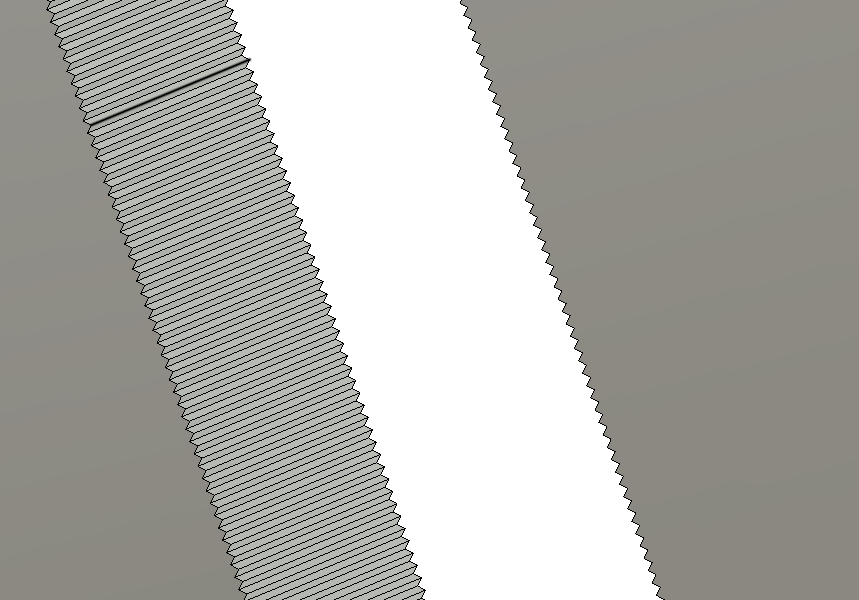
And ended up with this after slicing
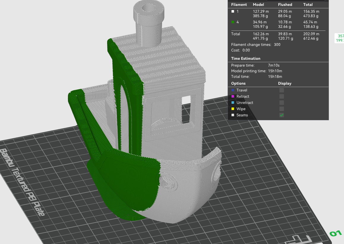
You will see from the simulated print that the join between the mirrored part and the standard printed part in the middle is now using the profile from the Fusion 360 cutter.
You still get walls between the mirrored and non mirrored part which is a bit wasteful - so I might do another GCODE post processor to do this type of segmentation too.
-
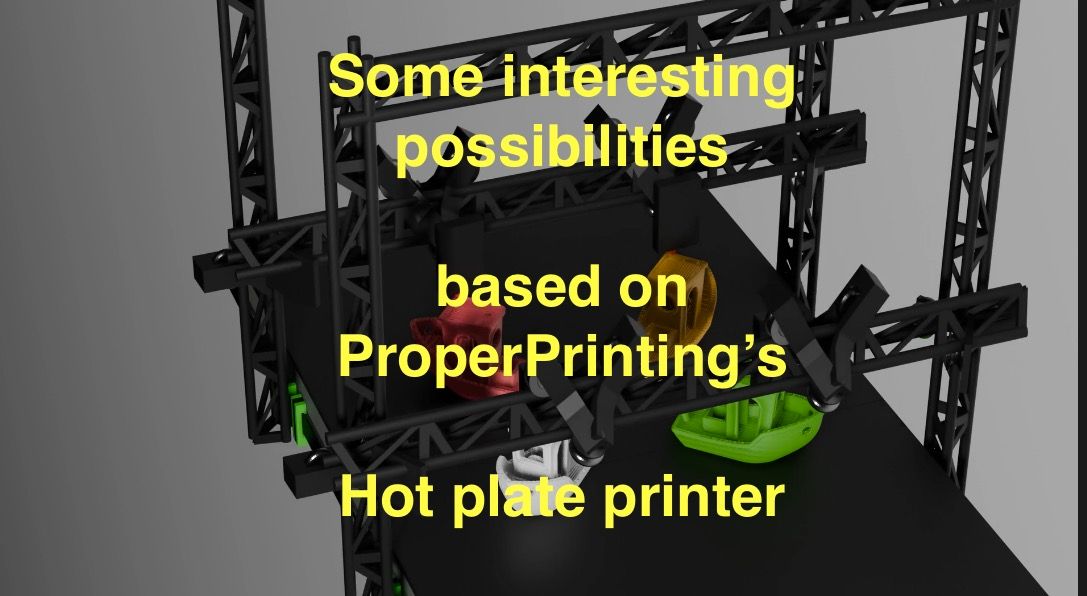
@properprinting hot plate double gantry version of Animations created.
IDEX Part 12 - Double Gantry Fixed Bed IDEX Youtube Video
-
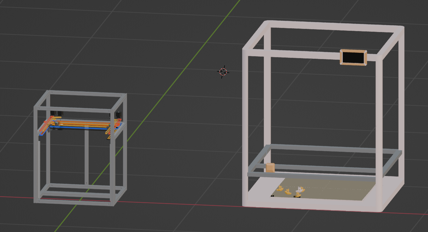
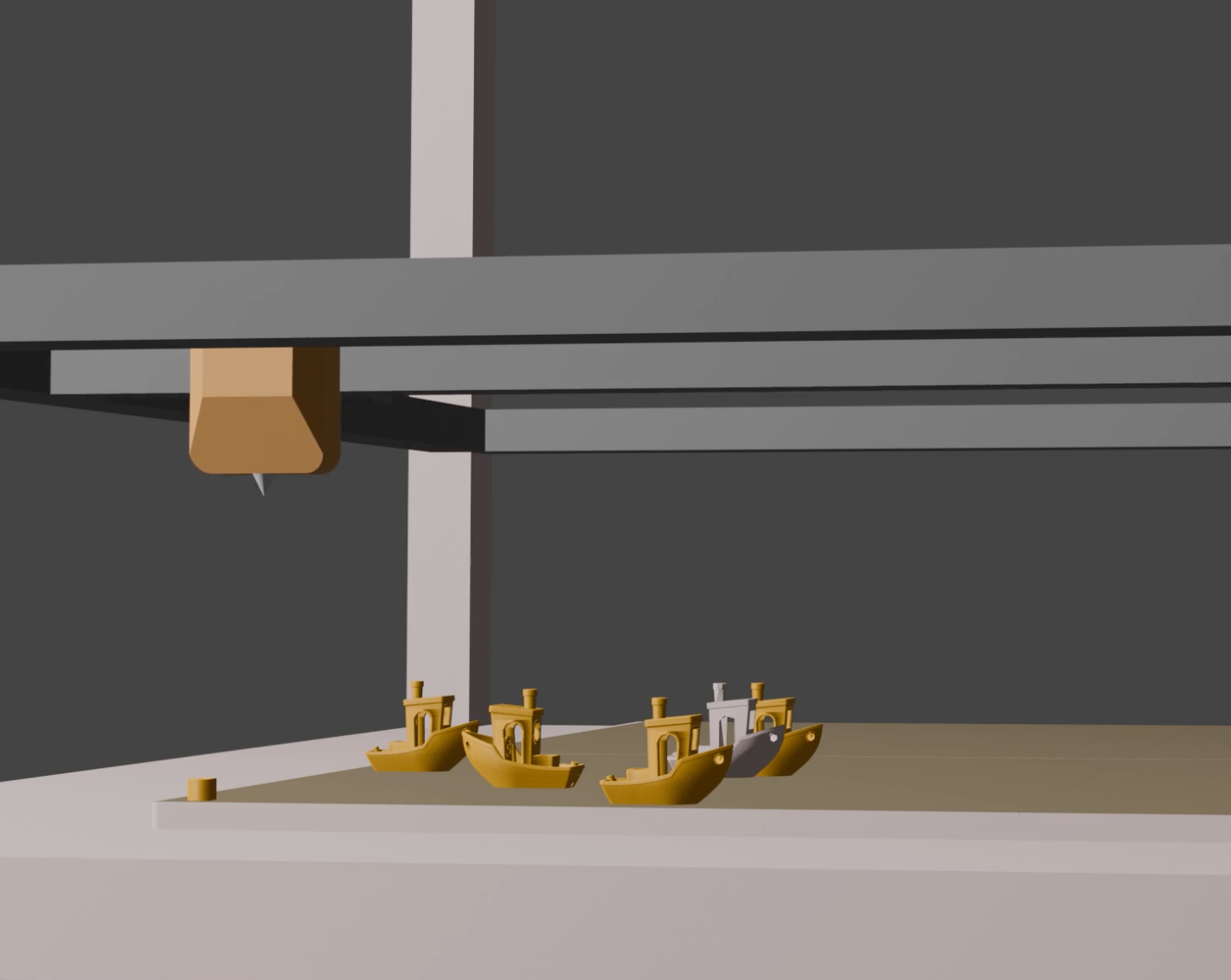
Upgrading virtual printer to a bigger platform (thanks to @UncleJessy for the Orangestorm Giga model on Printables). 800x800 build plate - should give plenty of room for at least 4 gantries - with 2 or more heads per gantry.
Pictured next to the Ratrig VCore 4 IDEX 400x400 I have been using - so exactly double the size.
Weight of the Z Axis could be a problem though.
-
@dwuk This is not quite what I meant. I meant a interlacing pattern, wide enougth to weld together the sparse infill:
This way you should retain close to full part strength and can put all perimeters in a single thread for optimal surface quality. Scince the sparse infill appears to be generated in relation to a global origin, this should work for arbitrary models and infill patterns when in parallel printing mode. For parallel mirror mode, you need a infill pattern that is and stays symmetrical to your mirror plane regardless of z-height. From the more performant infill patterns, cubic appears to work, when angle is changed to zero: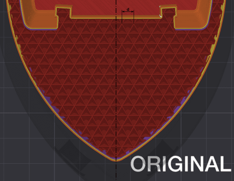
You can ignore the d-dimension. I dont know why I thought having the interlacing that wide would have been critical. I put my files on a printabels site, if you want to take a look, but cant post the link here due to lack of reputation. Ill put it in a Youtube comment for now. -
@JVan thanks for the clarification. Will add this into the y direction segmentation gcode processor and when I create X direction mirror and duplicate mode separator will add in alternate interlacing of layers based on the support pattern.
It will mean widening the minimum gaps slightly to avoid head clashes - but I should be able to mitigate this by optimising the placement of nozzles on extruders.
-
@dwuk Talking about interleaving infill reminded me of my regular CoreXYU, where I had one small nozzle for perimeters and a big nozzle for infill. I safed a lot of time doing "infill every n layers"
A four-head printer could have one big infill nozzle and three finer nozzles with different colours, I guess? -
@o_lampe. Interesting, I am intending to include some example print time comparisons with nozzles of different sizes in the same print. Is infill every N layers something that is available in any of the prusaslicer based slicers - as when I tried some comparisons (by using prusa XL profiles) it looked that you have to use the same layer height for the different nozzle sizes - which still brought some good savings.
-
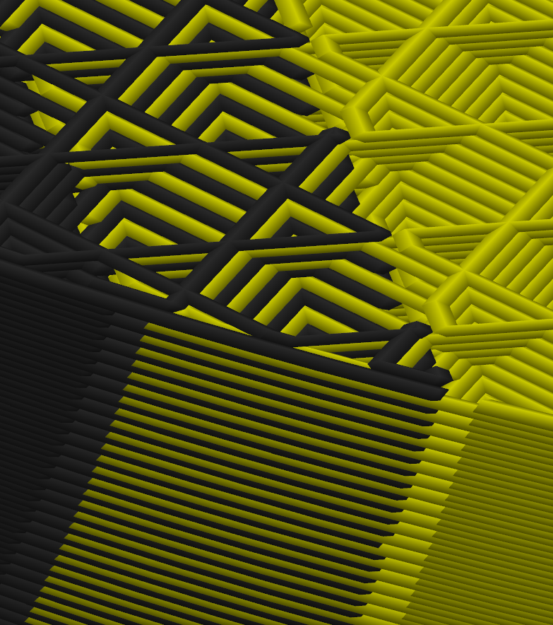
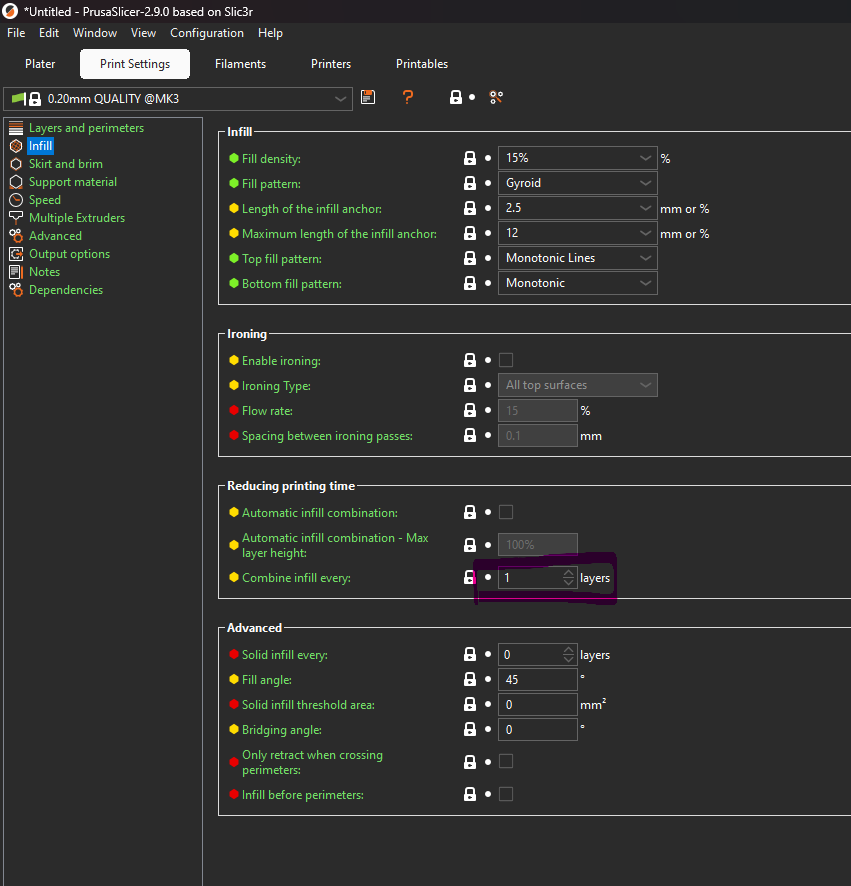
@dwuk Its this setting. Setting it to 2 will result in double height infill lines:
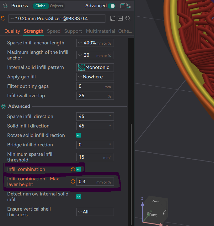
On Orca and (probably) Bambu its this. Here you set infill layer heigth directly. Either as mm or as % times nozzle diameter:
-
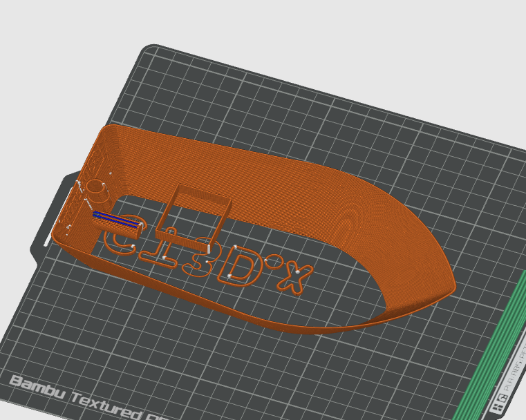
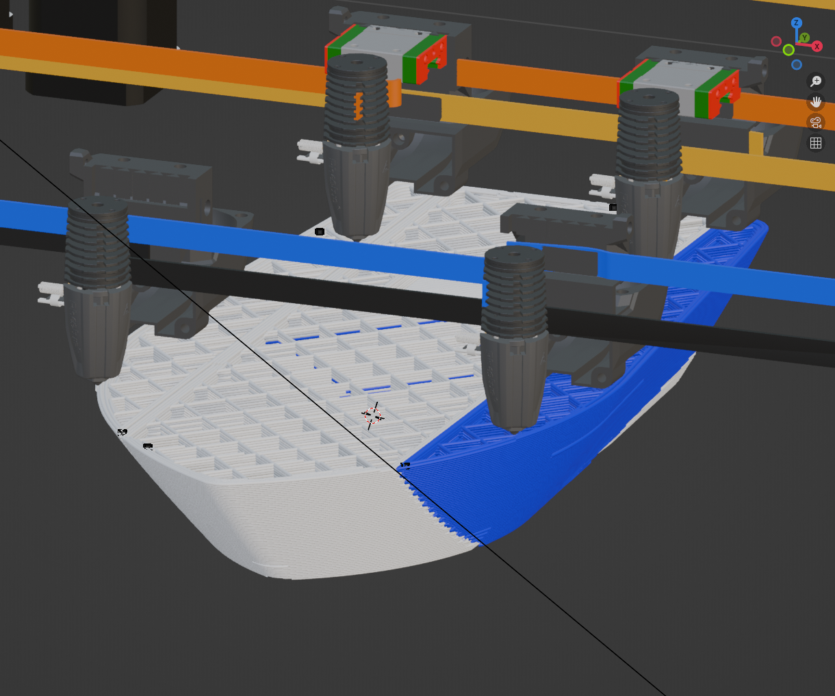
@JVan Added an option to colour each segment differently so that that they are easier to see.
Then for the parallel print segmentation I have simply offset all of the segments on alternate layers by a specified amount and I think it works quite well - so great idea thanks.
Screenshot with outer walls segmented - so that it is easier to see the offset joins
Or with the outer walls non segmented -
Will do the same to the mirrored segmented version next - will need to grow the width of the non mirrored section in the middle on both sides on alternate layers to get the same effect.
-
@JVan thanks - will try those options out.
My Blender simulator doesn't currently support multiple nozzle sizes - but should be fairly easy to add.
-
@dwuk said in IDEX BOTH ON CORE XY:
but should be fairly easy to add.
In the meantime, for simulation you can reduce infill to 25% of the actual value when you plan to use double layer thickness and twice the nozzle diameter.
-
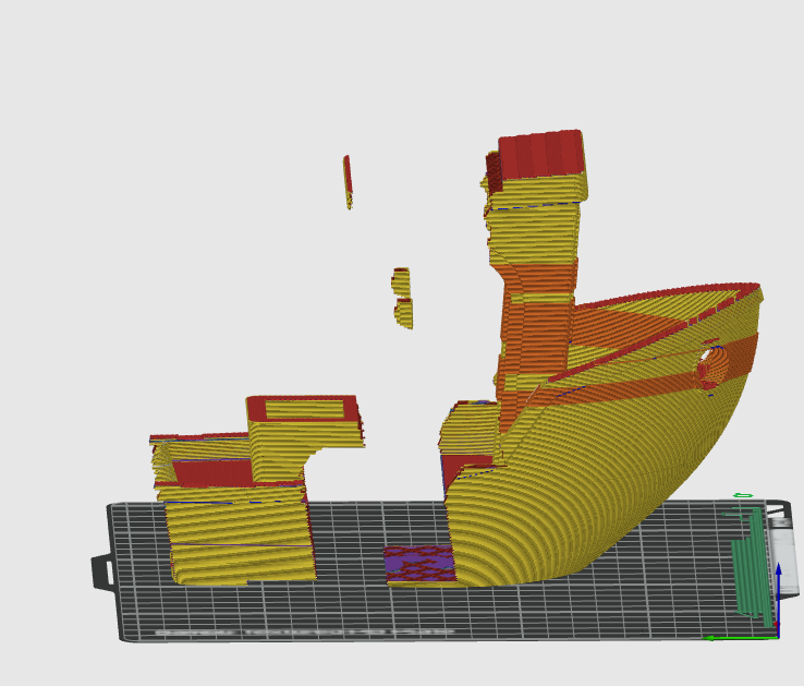
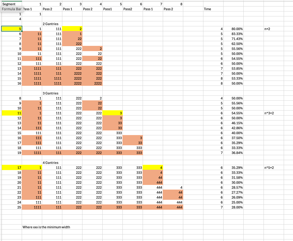
Trying to improve my algorithm for sizing the Y Axis segments when a) Up to 4 gantries are available and b) where the amount of extrusion time is unevenly spread across the print area.
In the first instance there are fairly big constraints on the minimum size of the segments due to the need to avoid head clashes.
Only when segments have reached their minimum sizes is there any benefit in using additional gantries in parallel.
And also it is only feasible to vary the start points and sizes of the segments to match better with where the extrusion is happening once the minimum sizes are all reached.
The attached is my attempt at working out (based on a minimum gap in the example of 3 or xxx) when it is worth starting to use extra gantries - which is highlighted in yellow.
The pink highlighted segments are then marked as the ones that can be varied in sized in order to better spread them over where the most work is needed on each layer.
I have changed my post processor to in its first pass collect an approximation of how much work is needed in each Y integer dimension in terms of raw extruding time - by dividing the length of the extruded move by the rate ( I know this is not completely accurate due to acceleration and deceleration) - and then dividing this by the Y movement and spreading these extrusions out evenly over each integer dimension in the range.
Will then try to use these calculated figures to help decide how the segments can be shifted around in order to make them as balanced as possible in each of the two passes.
Will then also consider slowing down the rates slightly in the segments that have the least work - so that ideally all print heads are in use for most of the time - rather than being intermittently idle and therefore causing oozing.
-
@dwuk It seems the post processor is pretty busy. Munching through GBs of gcode is much harder than splitting an .stl file of several MB.
Do you use an SBC or external CPU? It would be cool, if you could process layer by layer, while already printing.
You don't want the whole processing take longer than reducing printing time ...PS: Maybe you'll find a ready to use "center of gravity" calculation code? To me this is a close enough approximation for the best coordinate, where to put the cut.Would only work when cutting the .stl file I guess.... But maybe that's the right way of processing:- decide where to place and cut the object , based on the stl file
- then do the cut in the gcode file
-
@o_lampe Yes the code is getting a fair bit more complex. So far I don't think there any cross layer calculations so it could potentially be done just in time layer by layer, however ultimately I think it would best be done on the CPU that is doing the slicing (or as part of the slicer).
A present I am doing the processing on a MacBook Air in python.
I found an error in the segmentation of the early examples where I was using an X rather than Y coordinate - correcting this is making the segmented models look a look more evenly split.
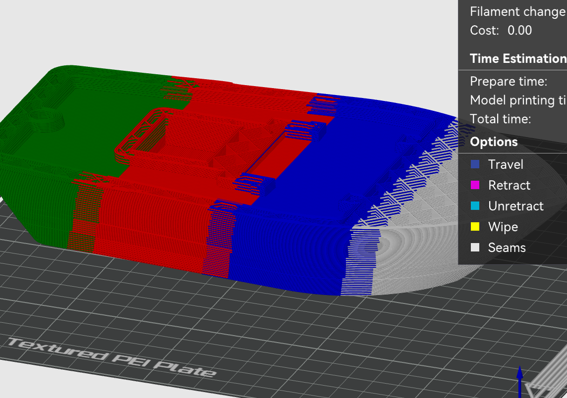
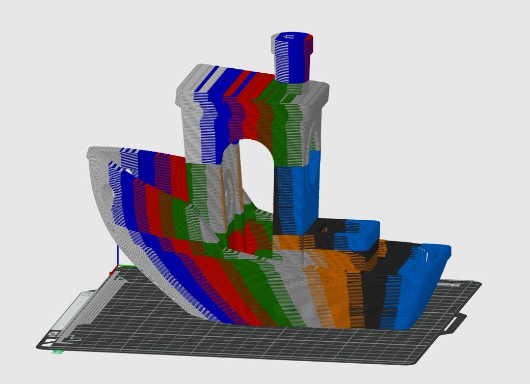
Just now need to address the slightly shifting around of segments for more efficient splitting - or for example the front (Green/Grey/Orange) and back (Black and Blue) of the cab in the attached 8 way segmented example (Shown without outer wall single threaded)
Version with layers alternately offset (probably a bit too far) for improved strength.
Will consider whether working the segments out from the centre (or most dense area) has any benefits when I am working on tweaking the segment boundaries for more efficient splits for parallel printing.
-
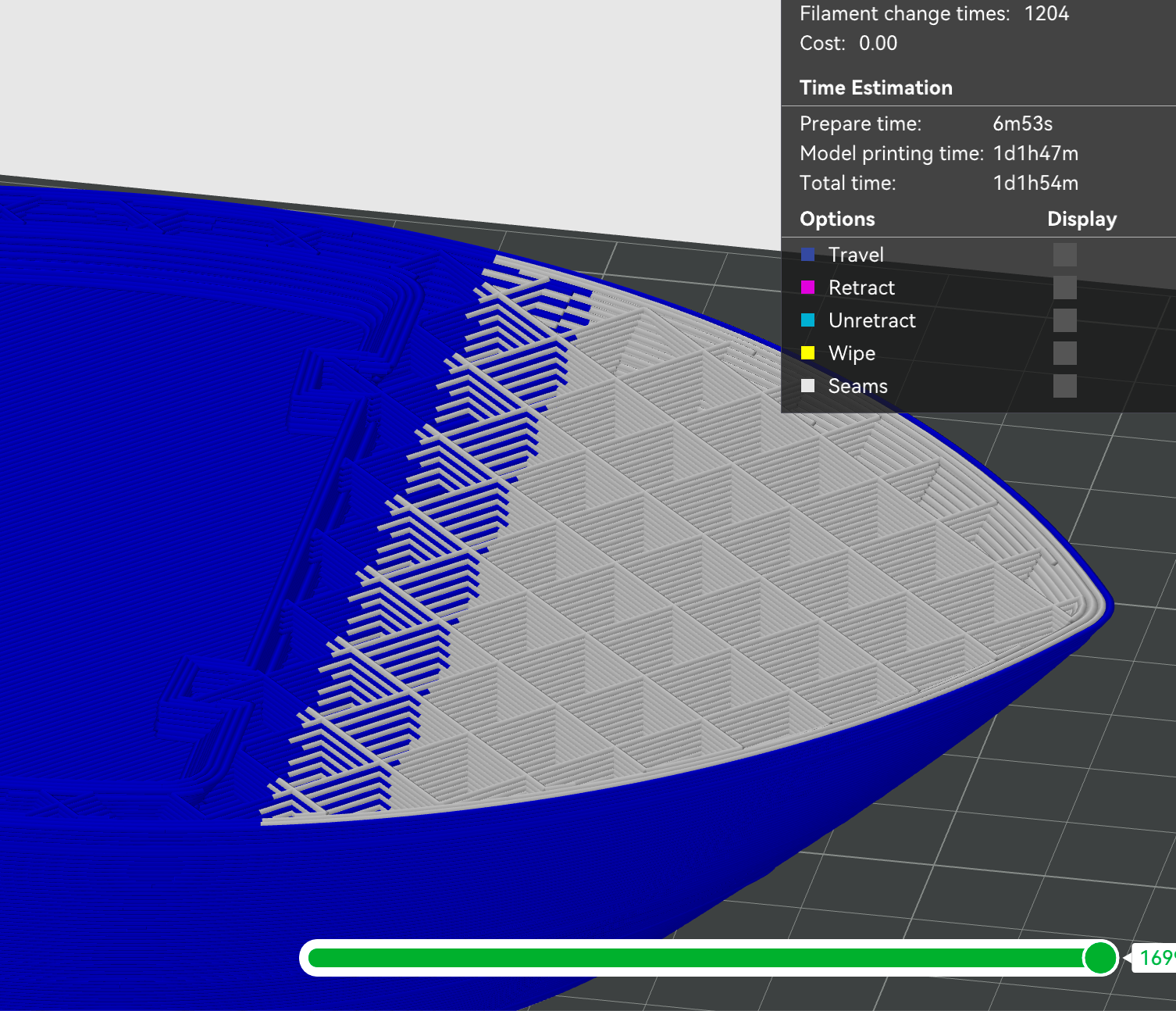
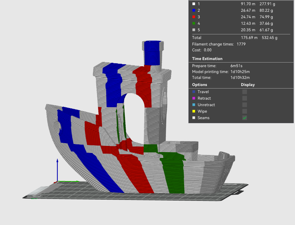
@dwuk Illustrated a bit better on this version with pass1 4xgantry nozzles all in white, with pass2 in multi colour - the issue I would like to address is the really thin (and therefore inefficient) green and red sections at the bottom front of the cab and white and the back of the cab.
-
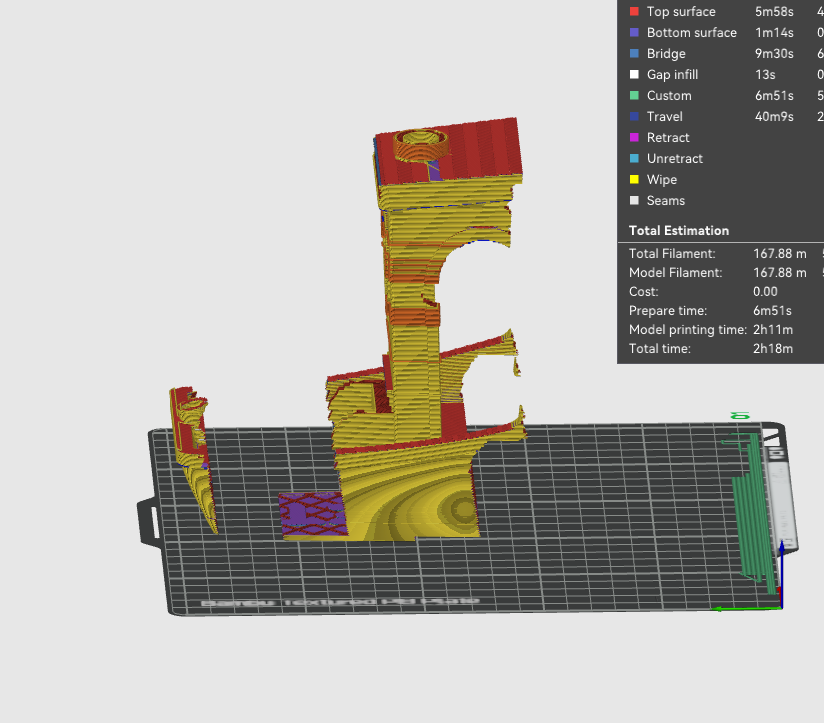
@dwuk Going down a bit of a rabbit hole with the tweaking - decided to try accurately calculating the time for extrusions - including acceleration and deceleration etc - not sure if these calculations are correct - but probably doesn't matter too much at this stage.
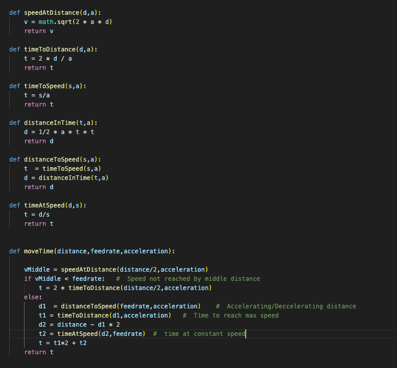
Then used this to select passes with segments in them which quite a big print time difference and then have simply taken the segment with the longest time and either reduced its size down to the minimum size it can be for head clash avoidance, or halved its size. I have then added this adjustment onto the segment with the shortest time.
It didn't select the layers I expected - probably because the segments in the cab are already at minimum size.
It makes the print look a bit more messy - but at least I can pick out the adjusted layers quite easily,
Will run some prints through my simulations with and without the adjustments to see if the layers that have been adjusted print any more efficiently.
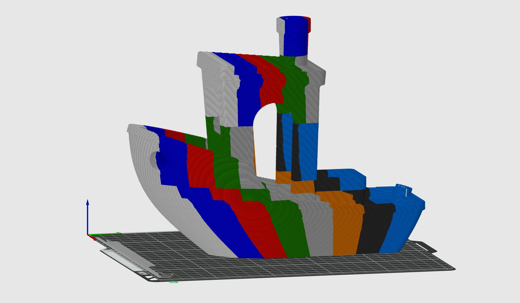
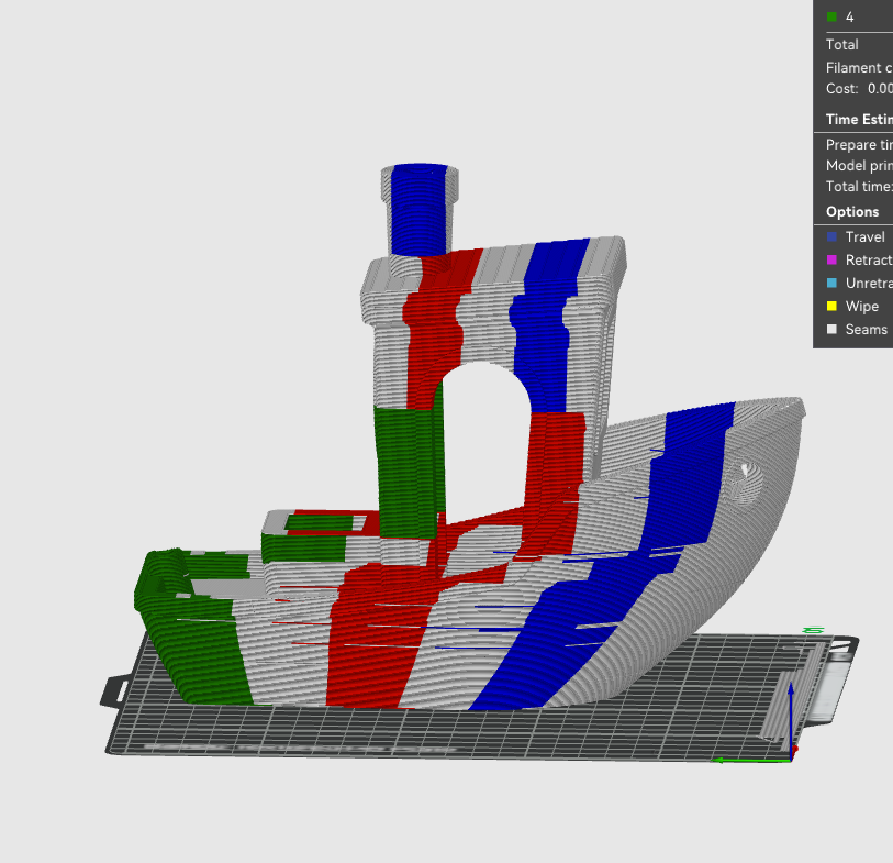
Example 3 gantry print shown - with pass1 heads shown in white and pass2 multi colour.
-
@dwuk I'm impressed, you came quite far with simulating all the different splitting algorythms.
But isn't it time to make split versions for one tool head? Just to see the real world output of your mods with inner layers overlapping and tons of retracts...I can think of several things that can go wrong trying to print the first layer. It's already nerve-wracking with a single object, although print surface and bed-adhesion has improved a lot.
We know from former dual tool printers, how hard it is to find the sweet spot regarding z-height (and without mesh levelling)
Somehow the second tool always scratched off the freshly laid tracks of tool one... -
@o_lampe Thanks and agreed - will be interesting to see some actual single print head test prints to see what I need to do in terms of retractions and zHopping etc. to get them to work. Printers currently out of action due to house guests - but hope to be able to get access again at the back end of the week.