Using tool distribution board for multiple Motors 23CL
-
@droftarts said in Using tool distribution board for multiple Motors 23CL:
@RockB The folder structure should be as shown here: https://docs.duet3d.com/en/User_manual/RepRapFirmware/SD_card#sd-card-structure
There should be a 'firmware' folder in the root, which is where firmware files are read from. The "Duet3Firmware_M23CL.bin" file should be in that. Make sure you're using the one from the 3.5.2 zip file. Ideally refresh it with a new copy, as it's usually a corrupt firmware file that gives the 'Bad firmware CRC' message.I have copied the fresh contents from 3.5.2 zip file to the firmware folder on SD card. (only the .bin files)
If you have a second firmware folder in the 'sys' folder, you can safely delete that.
The second firmware folder was actually within the main 'firmware' folder. I have deleted this second firmware folder.
Tested again after these changes. Same issue with fast blinking red led on motor.
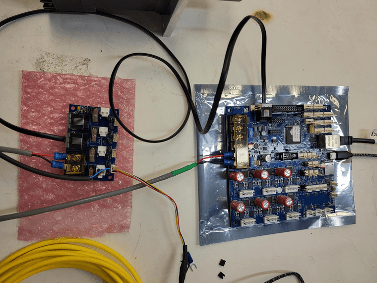
As far as I can tell, your wiring looks correct, with bypass jumpers removed from the Tool Distribution board for the connected tool, and the CAN termination jumper is in place. But I can't see the RJ11 cable between the Duet and the TDB, and I can't see the CAN wiring at the motor end. There's still a possibility that it's a wiring issue.
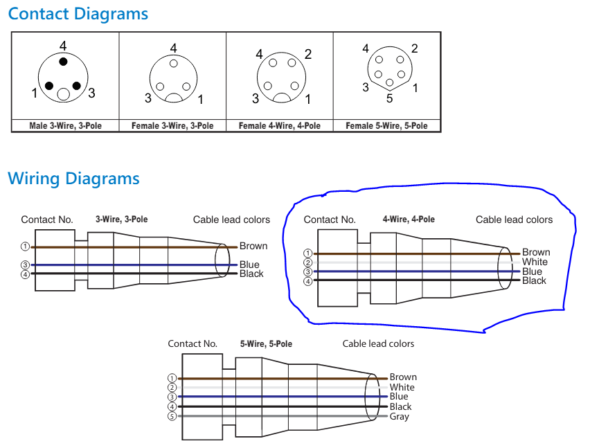
Here are some more pictures and wiring diagram:
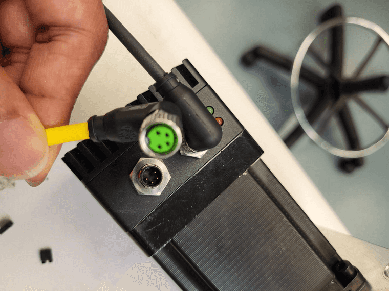
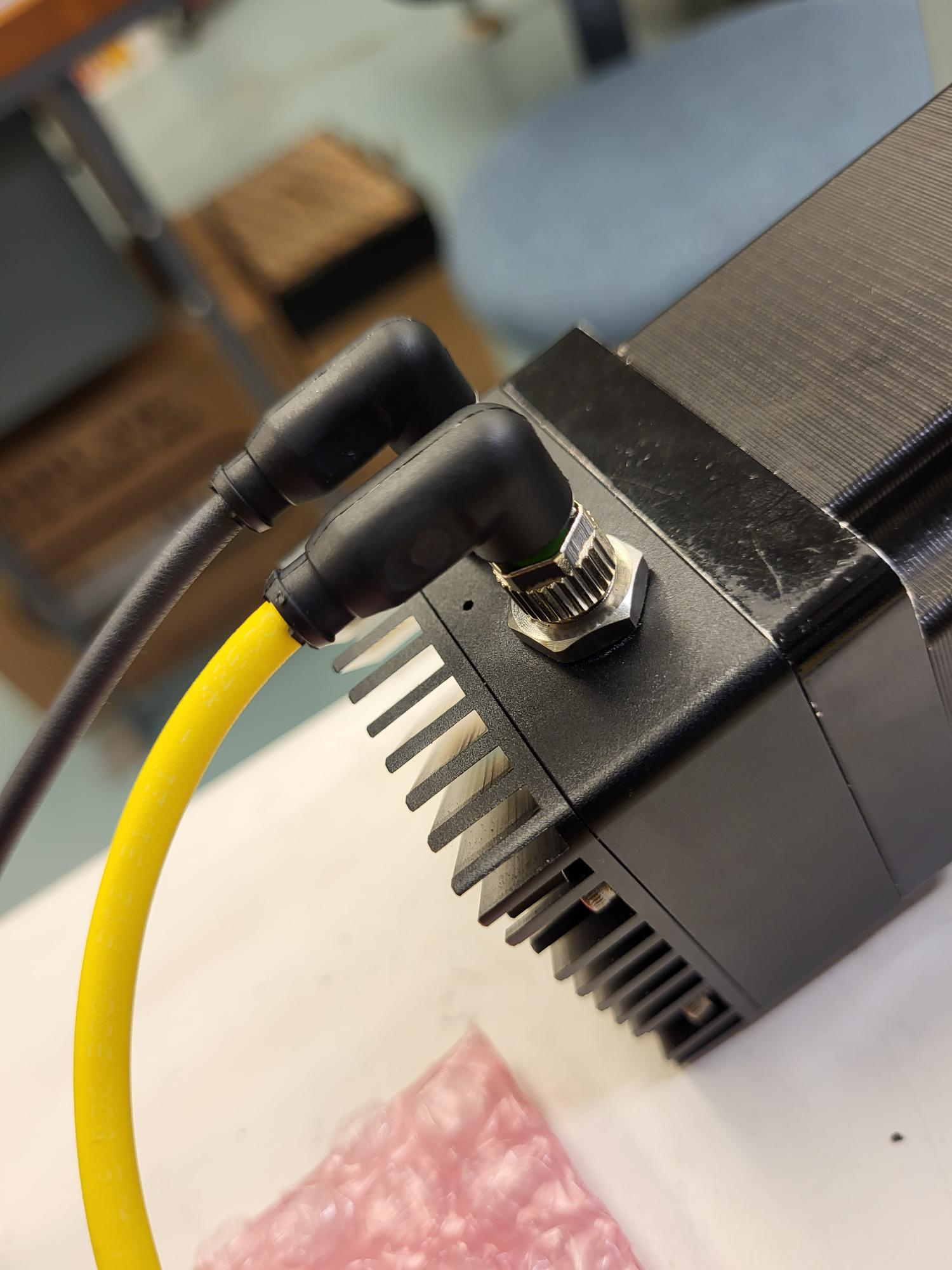
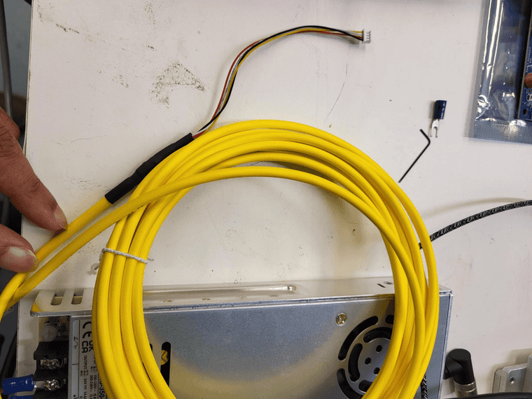
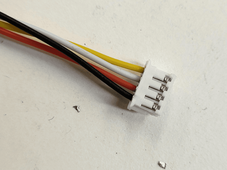
Soldering connection for coneecting 4-pin M8 cable with 4 pin JST-ZH cable:
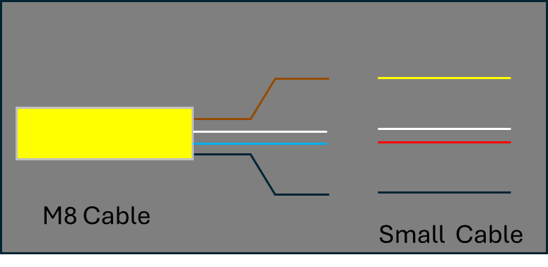
Manufacturer wiring diagram for M8 cable:
When you press the reset button on the 23CL, does anything show up in the console of DWC? If it is requesting firmware, I think you should get a message there.
Nope. I am not getting any message on DWC after I press the reset button.
uploading a custom RRF firmware for my machine
You have modified and compiled RRF for yourself? If so, please revert to the released version until we get this issue sorted out.
Apologies, I meant I have used RRF config tool to create a custom config for my machine. In the first config I created had multiple 23CLs and Tool1RRs called out in the config.g; however only one 23CL was connected to TDB for testing. I did get some errors like the Heater not found and so on since no Tool1RRs were connected at that time. I am not sure if this triggered the condition or had anything to do with it. One of my replies above contains the config.g file where I have commented out other axes, extruders, fans and tools while only 23CL is mapped to Z axis for testing.
Just to check the CAN connections, does it matter if a config.g file is present?
-
@RockB Thanks, as far as I can tell the motor wiring looks to be correct.
Could you wire up a Roto board, and see if you can get that to connect? It only needs power, and the two CAN wires connected to two of the pins on the TDB. Leave the bypass jumpers in place on the TDB, for the tool output you connect it to. Remove the 23CL CAN wiring, and put the bypass jumpers back in place there, too.
If the colours of the wires in both ends of the RJ11 cable are visible, check they are in the same order.
Ian
Bed-slinger - Mini5+ WiFi/1LC | RRP Fisher v1 - D2 WiFi | Polargraph - D2 WiFi | TronXY X5S - 6HC/Roto | CNC router - 6HC | Tractus3D T1250 - D2 Eth
-
@RockB said in Using tool distribution board for multiple Motors 23CL:
Just to check the CAN connections, does it matter if a config.g file is present?
It helps in that it starts up the network, but you don't need anything configured in config.g to check a board is on the CAN bus.
Ian
-
@RockB said in Using tool distribution board for multiple Motors 23CL:
It always used to flash red led quickly as seen in my video above. Whenever the motor is powered with reset pressed, it flashes both red and green led once and then reverts back to continuous flashing of red led once the reset is released.
How fast is it flashing? Once a second means it is connected to the main board and running normally. Several times a second with no pauses means it doesn't have communication with the main board. Several times with pauses means it is reporting an error code.
-
@droftarts @dc42
I finally figured out this issue. I swapped out TDB with a new one and things started working. The red LED now blinks every second showing the Motor can communicate with the mainboard. I also tried wiring the roto toolboard to the same TDB as the stub and that also worked well.
I can communicate to both devices using M122 and M115.The TDB was purchased recently from Filastruder. Any thoughts on why this would go bad?
-
@RockB The TDB is a pretty simple, passive, device, so there's not much to go wrong. It's possible there's a soldering fault on it, I suppose. Or maybe the pins in the CAN connector is misaligned. Can you take a picture of both sides of the board and post them?
Ian
Bed-slinger - Mini5+ WiFi/1LC | RRP Fisher v1 - D2 WiFi | Polargraph - D2 WiFi | TronXY X5S - 6HC/Roto | CNC router - 6HC | Tractus3D T1250 - D2 Eth
-
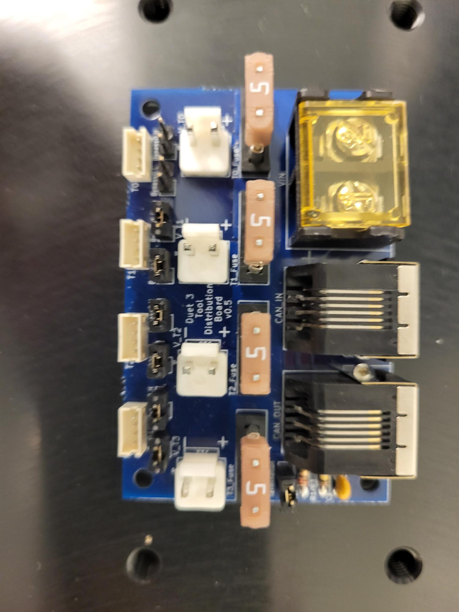
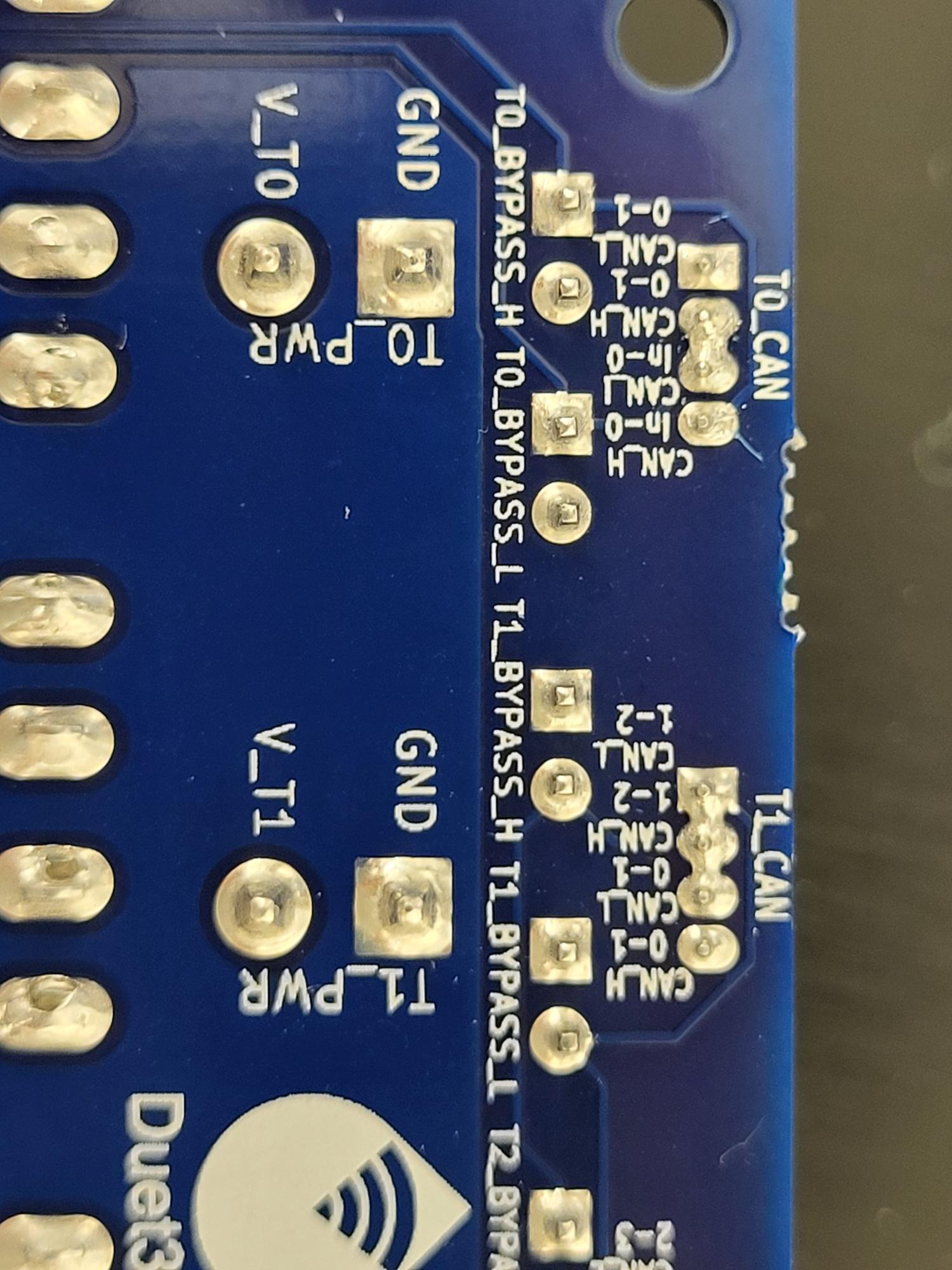
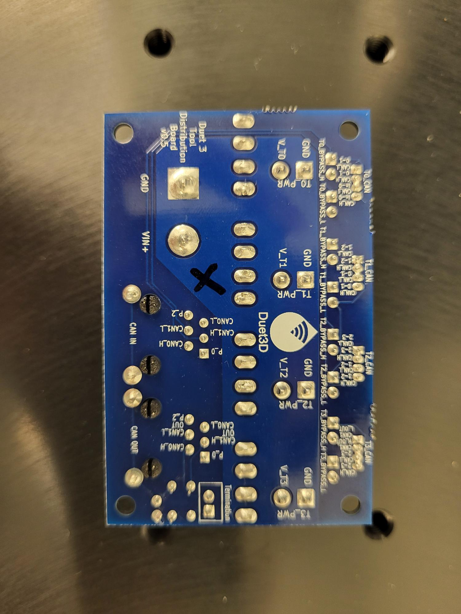
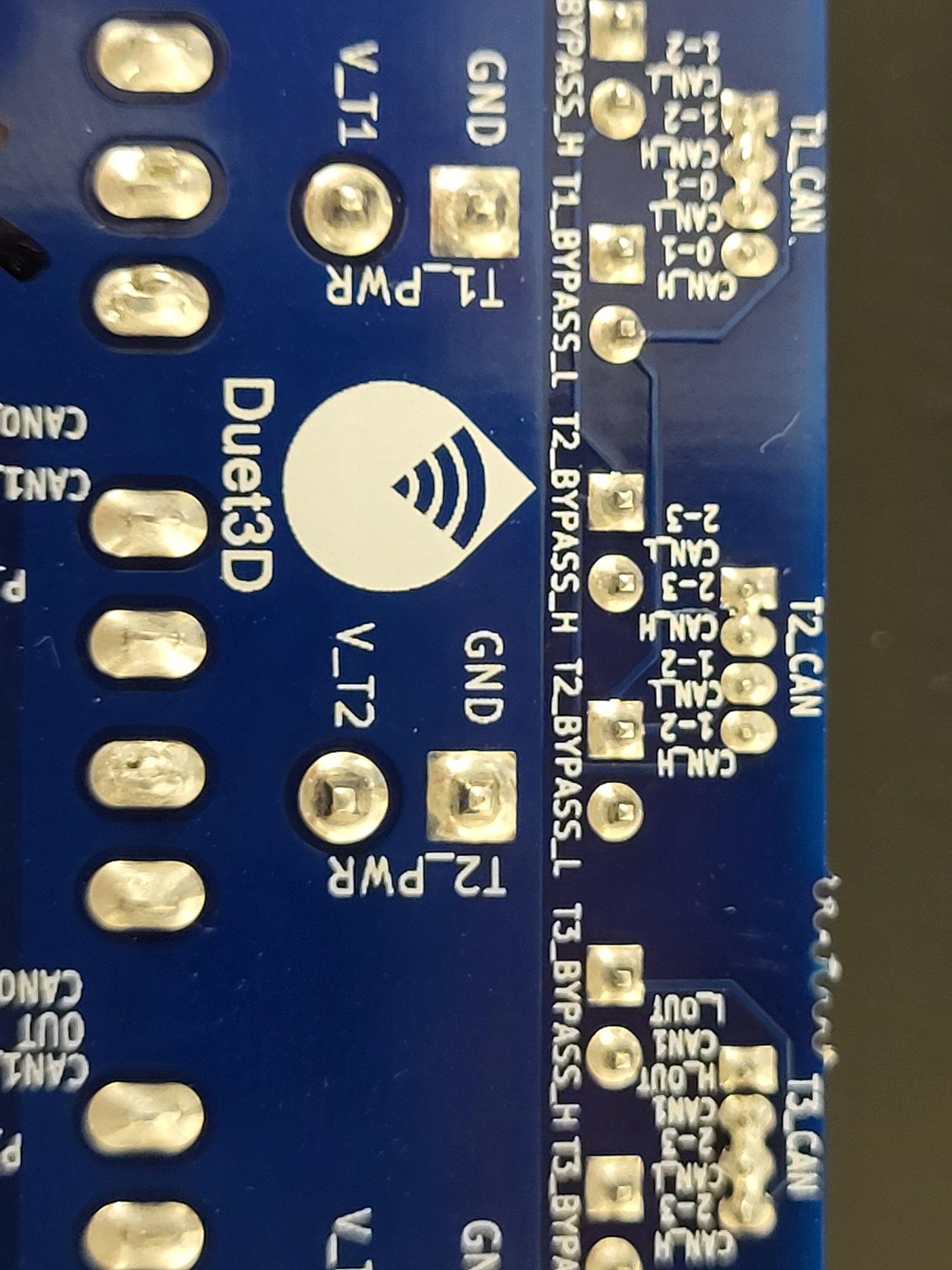
@droftarts Ian, It indeed does look like a poor soldering job. Following are some pictures. CAN_H and CAN_L pins seems to be soldered together on more than one 'tool' outputs
Note: The black 'X' mark is my way to identify bad board from another.
What's the procedure to get a refund or replacement of these boards?
Purchased from Filastruder (@elmoret) -
@RockB Yikes, that's poor. The assembly company must have had the trainees on the tools that day! Yes, no problem, we'll replace under warranty. Please send an email to warranty@duet3d.com and CC your reseller. Include a link to this forum thread and the details of your original purchase. You'll receive a reply with a form to fill out.
If you don't want the hassle of waiting for a replacement, and you're comfortable waving a soldering iron around, I'm happy if you want to clean up the solder yourself, and we'll continue to honour the warranty. Though it would be good to get that board back and show the assembly company!
Ian
-
 undefined nachogil referenced this topic