BLT function
-
@Bridge-Of-Don said in BLT function:
I suspect that I will also need to invert the Z drive as it also lifts the bed towards the extruder when use Z+ option on dashboard!! (AND when I try and home X or Y the bed LIFTS not drops .....)
Yes that sounds right. Your Z axis is inverted. You should fix that before trying any further Z axis homing.
@Bridge-Of-Don said in BLT function:
Am I better to rewire ALL three drives so that they are all running 'forwards' in case there are other issues later?
Either or. You can rewire, or do it in the config. Makes no difference as long as the motor is going to right way.
@Bridge-Of-Don said in BLT function:
The screen remains at 1000 regardless of BLT deployed or retracted.
That means the probe is in a triggered state all of the time. Also indicated by the error message.
@Bridge-Of-Don said in BLT function:
The BLT is wired we reckon correctly (no expansion board) so using 1,2, 8 as per image.
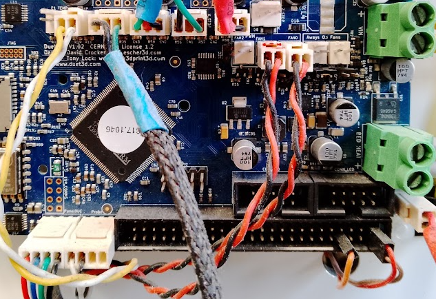
Can you show a photo of the wiring?
@Bridge-Of-Don said in BLT function:
Does the 'Home Z' on the dashboard run the 'Homez.g' routine?
Yes. All homing moves are defined in the homing macros. Homex.g homey.g homez.g and homeall.g. Those are used by the web interface or when sending the gcode command G28.
-
OK, I'll just reverse the drives within the CONFIG, much easier as the wires are all into the small multi-way connectors. The real reason to ask was in case there were 'numerous' other locations that I'd have to edit the G code.
The photo I referred to was the one shown on the 'how to' page
https://docs.duet3d.com/User_manual/Connecting_hardware/Z_probe_BLTouch
our unit didn't come with a multi plug, just a double and a single.
Much of the wiring is a little 'ropey' / 'suspect' , various colours/plugs/types etc !
but as we were handed it for free, then we should not complain?I'll try the config and 'homing' next week, hopefully this will resolve the setting up?
Should the probe deploy 'just before' the Z drive begins moving?Alan
-
Normally the BLtouch will read 0, and when the pin touches it will flash briefly to 1000 when triggered and return to 0 as the pin retracts.
Yours indicates that it is already showing as triggered. Seeing your photo, the white wire on the probe connector is the signal wire for the bltouch.
But your config says you have the
"^exp.thermistor3"pin used for the signal wire.Here's my config for comparison
M950 S0 C"exp.heater3" ; create servo pin 0 for BLTouch
M558 P9 C"^zprobe.in" H3 F60 T12000
I think the main problem is that your pin name is incorrect for how it's connected.
M558 K0 P9 C"^exp.thermistor3"should beM558 P9 C"^zprobe.in"The K0 is optional since you only have a single probe.
-
@Phaedrux said in BLT function:
Normally the BLtouch will read 0, and when the pin touches it will flash briefly to 1000 when triggered and return to 0 as the pin retracts.
Yours indicates that it is already showing as triggered. Seeing your photo, the white wire on the probe connector is the signal wire for the bltouch.
But your config says you have the
"^exp.thermistor3"pin used for the signal wire.Here's my config for comparison
M950 S0 C"exp.heater3" ; create servo pin 0 for BLTouch
M558 P9 C"^zprobe.in" H3 F60 T12000
I think the main problem is that your pin name is incorrect for how it's connected.
M558 K0 P9 C"^exp.thermistor3"should beM558 P9 C"^zprobe.in"The K0 is optional since you only have a single probe.
Ah, OK, we ran the RepRap configuration so hoped I'd made all the correct choices but maybe I'd mis-understood what the 'heater' connection was!!
I'll edit as per your suggestion and report back on how we get on.
Thanks again for the pointers.
Alan
-
Some more success this week.
The BLTouch appears to function and stops bed movement then 'lowers' around five mmWhere should the nozzle end up after 'Home ALL' ?
Should it be 'about middle' and a few mm (6.7) away from bed?
I can see that Home X & Home Y run the carriages until they hit the micro switches, and then Home Z seems to push the nozzle to middle of the bed (although I changed this section X{var.xCenter} Y{var.yCenter} to be X 150, Y150 as I couldn't see where the Duet unit created this variable from?? and knew if it tried to probe the bed when at X=0 & Y=0 then it would fail as this is in 'fresh air'
")
move.compensation.probeGrid.mins[0]
obviously the var xCenter comes from the 'calculation' after the = sign; home XY
var xTravel = move.axes[0].max - move.axes[0].min + 5 ; calculate how far X can travel plus 5mm
var yTravel = move.axes[1].max - move.axes[1].min + 5 ; calculate how far Y can travel plus 5mm
G91 ; relative positioning
G1 H1 X{-var.xTravel} Y{-var.yTravel} F600 ; coarse home
G1 H1 X{-var.xTravel} F600 ; coarse home in the -X direction
G1 H1 Y{-var.yTravel} F600 ; coarse home in the -Y direction
G1 X5 Y5 F6000 ; move back 5mm
G1 H1 X{-var.xTravel} Y{-var.yTravel} F300 ; fine home
G1 H1 X{-var.xTravel} F300 ; fine home in the -X direction
G1 H1 Y{-var.yTravel} F300 ; fine home in the -Y direction
G90 ; absolute positioning; home Z
var xCenter = move.compensation.probeGrid.mins[0] + (move.compensation.probeGrid.maxs[0] - move.compensation.probeGrid.mins[0]) / 2 - sensors.probes[0].offsets[0]
var yCenter = move.compensation.probeGrid.mins[1] + (move.compensation.probeGrid.maxs[1] - move.compensation.probeGrid.mins[1]) / 2 - sensors.probes[0].offsets[1]
G1 X{var.xCenter} Y{var.yCenter} F6000 ; go to bed centre
G30 ; probe the bedwe are still getting a few error messages when attempting to 'Home X or Y' that I over-ride with the M564 S0 H0 command, need to figure out why!
Now we have a functioning movement we can look at getting the wiring sorted as there are broken wires at the heater/nozzle etc and didn't feel any need to tidy those if there were other issues!!
-
@Bridge-Of-Don said in BLT function:
I couldn't see where the Duet unit created this variable from??
It knows the length of the X and Y axis from the M208 command. So if that's correct, then it should work. The firmware has an object model of various machine parameters that can be used for programming macros etc.
@Bridge-Of-Don said in BLT function:
Where should the nozzle end up after 'Home ALL' ?
Should it be 'about middle' and a few mm (6.7) away from bed?
That's entirely up to you. When it's finished probing it would be sitting at the same spot it was positioned before probing. It's up to you if you want to stow the print head away at that point, maybe by homing X and/or Y a second time to move it back. Or since homing is usually done before a print anyway just leave it there.
@Bridge-Of-Don said in BLT function:
we are still getting a few error messages
what error messages are you getting?
-
Thanks, I changed the 'HOME Z' & 'HOME ALL' to use the variable but then it attempts to probe at the X=0, Y=0 so reverted back to X150 Y150 and that seems to be fine, and always probes at centre of the build plate.
M208 X0:300 Y0:300 Z0:300 ; set minimum and maximum axis limitsWe cannot get the 'Home' functions to work unless I send M564 S0 H0, we don't have any MACROS
05/06/2024, 09:10:59 M98 P"config.g"
HTTP is enabled on port 80
Warning: Heater 0 predicted maximum temperature at full power is 321°C
05/06/2024, 09:30:21 G28 X
Error: in file macro line 8: G1: insufficient axes homed
05/06/2024, 09:32:16 M564 S0 H0
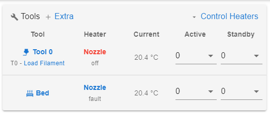
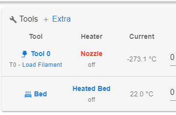
05/06/2024, 09:45:10 Upload of homez.g successful after 0sAlso I seem to have an issue with the bed temperature, we measure 132k Ohms at the connector but still shows -273C, suggesting open circuit? OR a misconnection/configuration, even when plugged into the bedthermistor port
; Sensors
M308 S0 P"bedtemp" Y"thermistor" A"Heated Bed" T130000 B4725 C7.06e-8 ; configure sensor #0
M308 S1 P"e0temp" Y"thermistor" A"Nozzle" T100000 B4725 C7.06e-8 ; configure sensor #1; Heaters
M950 H0 C"e0heat" T1 ; create heater #0
M143 H0 P0 T0 C0 S140 A0 ; configure heater monitor #0 for heater #0
M307 H0 R2.43 D5.5 E1.35 K0.56 B0 ; configure model of heater #0
M950 H1 C"e1heat" T1 ; create heater #1
M143 H1 P0 T1 C0 S285 A0 ; configure heater monitor #0 for heater #1
M307 H1 R2.43 D5.5 E1.35 K0.56 B0 ; configure model of heater #1As a test we pulled the thermistor from the bed connector and put onto (E0) to nozzle as the wires are broken on nozzle but I must have an error on the config? as the same temperature is shown on both . .. . as per image
-
@Bridge-Of-Don xCenter and yCenter are defined by these two lines:
var xCenter = move.compensation.probeGrid.mins[0] + (move.compensation.probeGrid.maxs[0] - move.compensation.probeGrid.mins[0]) / 2 - sensors.probes[0].offsets[0] var yCenter = move.compensation.probeGrid.mins[1] + (move.compensation.probeGrid.maxs[1] - move.compensation.probeGrid.mins[1]) / 2 - sensors.probes[0].offsets[1]It uses the bed mesh grid set by M557, so if you don't have this set, the numbers will be 0.
We cannot get the 'Home' functions to work unless I send M564 S0 H0, we don't have any MACROS
05/06/2024, 09:30:21 G28 X
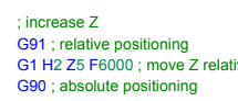
Error: in file macro line 8: G1: insufficient axes homedYou do have macros; you have the homing macros in /sys folder, homex.g, homey.g, homez.g, homeall.g. I expect in the homex.g macro (and maybe the others) you have this move:
; increase Z
G91 ; relative positioning
G1 Z5 ; move Z relative to current position to avoid dragging nozzle over the bed
G90 ; absolute positioning
If the Z axis is not homed, you will get an error, because
G1 Z5is a 'normal' move. It should beG1 H2 Z5. The H2 makes it a move that ignores the machine limits. See https://docs.duet3d.com/en/User_manual/Reference/Gcodes#g0g1-h-and-s-parameterAlso I seem to have an issue with the bed temperature
There's an error in your config.g. You're using the same temperature sensor (T1, the one for the nozzle) for both bed and nozzle:
; Heaters
M950 H0 C"e0heat" T1 ; create heater #0
...
M950 H1 C"e1heat" T1 ; create heater #1
Change the M950 H0 entry to T0.
For the actual sensor configuration:
M308 S0 P"bedtemp" Y"thermistor" A"Heated Bed" T130000 B4725 C7.06e-8 ; configure sensor #0
M308 S1 P"e0temp" Y"thermistor" A"Nozzle" T100000 B4725 C7.06e-8 ; configure sensor #1
I know these are the defaults for thermistor values in the config tool, but they are unlikely to be correct. Do you know what thermistors are being used? Your bed is likely to use a standard thermistor. Your hot end looks like an E3D V6. So you are likely to get more accurate temperature reporting if you use the following:
M308 S0 P"bedtemp" Y"thermistor" A"Heated Bed" T100000 B3950     ; configure sensor #0
M308 S1 P"e0temp" Y"thermistor" A"Nozzle" T100000 B4388 C7.06e-8 ; configure sensor #1
Ian
-
@droftarts
Ian, magic those are the pointers we need.
I'll stick with the X150 Y150 as it does no real harm?I didn't think that the 'Home, X, Y, Z & ALL were 'macros'
Yes the Home X, Y, Z macros onlyhave G1 Z5, again from the 'default' config created by RepRap
The Home ALL is subtley different, so I'll just add the H2 to the three others to avoid issues
No idea what thermistors or heaters are fitted, although both the thermistors are sitting at around 130000 Ohm when at room temp so happy to change to your suggestion.easy to swap the M950 H0 T1 to T0, I was looking at the wrong part of the code ie the sensors M308
I'd assumed that the Heaters was the connections for the power out, not measuring the result ?
Ref the text "e1heat", should this read "bed"? just for clarity going forward? we plan to leave it plugged into the 'Bed Thermistor' input now proved that it works.
I think we are now getting to a stage where we need to tidy the wiring by removing the random bits of cable and connectors (lots of the wires at extruder have 3" extensions & plugs on each end) no idea why.....
then possibly can report back next time a functioning unit ?
-
@Bridge-Of-Don said in BLT function:
I'll stick with the X150 Y150 as it does no real harm?
That's fine!
I didn't think that the 'Home, X, Y, Z & ALL were 'macros'
Anything that's a bit of code that can be called is effectively a macro, so all gcode in /sys is effectively a macro, just isn't in the /macros folder!
Yes the Home X, Y, Z macros only have G1 Z5, again from the 'default' config created by RepRap
Thanks, this appears to be a bug in the config tool, I have alerted @chrishamm. Change them to
G1 H2 Z5.both the thermistors are sitting at around 130000 Ohm when at room temp
That probably means room temperature is about 20C. The T value is the resistance at 25C.
Ref the text "e1heat", should this read "bed"? just for clarity going forward?
I guess the output is controlling a Solid State Relay (SSR), which turns the bed on and off? If so, you can use either, as the SSR shouldn't draw very much current. If you do change it to 'bed', you'll need to move the wires to the SSR to the heated bed output.
Ian
-
@droftarts said in BLT function:
both the thermistors are sitting at around 130000 Ohm when at room temp
That probably means room temperature is about 20C. The T value is the resistance at 25C.
Ref the text "e1heat", should this read "bed"? just for clarity going forward?
I guess the output is controlling a Solid State Relay (SSR), which turns the bed on and off? If so, you can use either, as the SSR shouldn't draw very much current. If you do change it to 'bed', you'll need to move the wires to the SSR to the heated bed output.
Ian
Ian
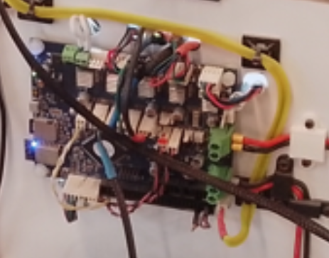
Aye the heated bed has a stonking big SSR to control it and it is wired into the Bed output, so it will have to be on/off rather than anything fancy like PWM?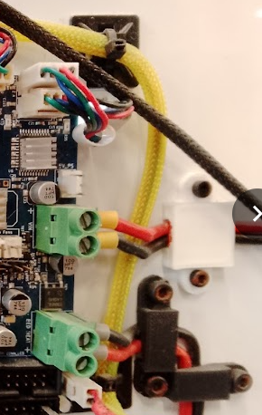
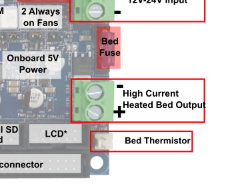
although it switches the 'negative' supply?!I think I'd be happier changing this to the bed output connection as per image? as then it makes life simpler for anybody trying to follow what we have fixed/corrected, rather than fudged?
@droftarts said in BLT function:
M950 H1 C"e1heat" T1 ; create heater #1
I assume the text should be
M950 H1 C"bedheat" T1 ; create heater #1
so that this controls the correct output for the bed if using the 'High Current Heated Bed'?
This is an example of the wiring that needs 'tidied'
PS I'm glad that it wasn't just my wrong doing about the 'default config'
Thanks againAlan
-
Progress
ALL the X, Y & ALL homing work, I had to add H2 to a few places at the end of each routine, maybe not 'elegant' but fixed error messages
; decrease Z again
G91 ; relative positioning
G1 H2 Z-5 F6000 ; move Z relative to current position
G90 ; absolute positioningStill to fix the wiring for nozzle thermistor but at least the sensors are correct and the temperature reading moves with the sensor (if I swap them), so maybe a blessing that one wire was broken?
Alan
-
@Bridge-Of-Don said in BLT function:
I had to add H2 to a few places at the end of each routine
That's correct, as again Z may not be homed, so you would get an error message when it tried to move back to the original Z height. Again, I've alerted @chrishamm to this, so he can update the config tool to fix this. Thanks!
I think I'd be happier changing this to the bed output connection as per image? as then it makes life simpler for anybody trying to follow what we have fixed/corrected, rather than fudged?
Using an SSR to control the heated bed isn't a fudge. Unless you know how much current the bed draws (you can measure the current to get an idea), I'd leave it in place. The Duet 2 bed heater output can support a bed that draws up to 15A, but it's possible that the replacement bed draws significantly more than that. For example, a 300x300mm bed that draws 15A would have an output of 360W at 24V, and a resistance of 1.6ohms, and should be able to get to 100C.
You can use PWM control, rather than bang-bang, on an SSR, but you might have to slow down the switching frequency. Check the manufacturer's datasheet for the SSR.
Also worth checking if the heated bed runs off the same PSU as the Duet, or a different one which could be wired to the SSR. What PSU(s) is/are fitted? Output voltage and current or wattage capacity would be good to know.
Ian
-
@droftarts
Ian, by 'fudge' I meant connecting the heated bed to a different 'output' it already has wiring from the 'BED HEATER' to the SSR and so I'd rather leave that as it is, saves (over)loading the Duet board and simpler to swap a SSR than a Duet")
I can check the SSR specs as well to see how fast it can be switched, especially if using PWM will give a more consistent temperature across the bed....
Not sure about the power supply's spec (and away from the shed now for a few weeks) but I assume that if it was working previously then I'll leave alone?
If not enough supply amps then I'm sure i have some Switched mode supplies 'lurking' in garage.
We greatly appreciate the help given so far!!!
Alan
-
@Bridge-Of-Don said in BLT function:
it already has wiring from the 'BED HEATER' to the SSR
If that's the way it was wired already, then yes, the config.g is still a bit wrong. The bed heater 'traditionally' uses sensor 0 and heater 0, and the first hot end as sensor 1 and heater 1 (slightly confusing because this becomes 'Tool 0').
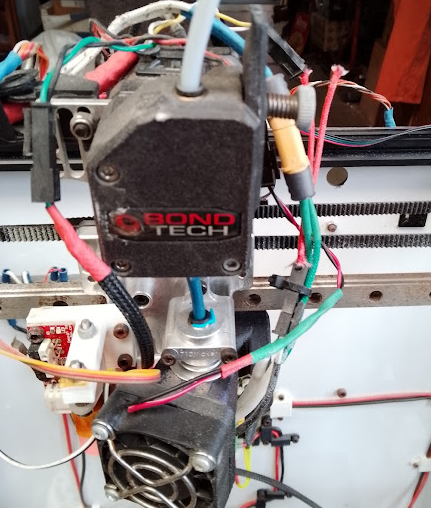
I think there's another error; from your picture in this post https://forum.duet3d.com/post/339699 it looks like the hot end heater is connected to e0heat (two white wires that go through the back panel), not e1heat:
The hot end thermistor is, I guess, the yellow and white cables connected to e0temp. I'm not sure why it's reading -273C, when I think you said you measured 130000 ohms. Perhaps you changed something else? I think the thermistors and heaters should be set as:
; Sensors
M308 S0 P"bedtemp" Y"thermistor" A"Heated Bed" T100000 B3950     ; configure sensor #0
M308 S1 P"e0temp" Y"thermistor" A"Nozzle" T100000 B4388 C7.06e-8 ; configure sensor #1

; Heaters
M950 H0 C"bedheat" T0 ; create heater #0
...
M950 H1 C"e0heat" T1 ; create heater #1
I also notice you have the two Z motors connected to the Z axis motor connector. That's fine, because they will be synchronised and work together, but you could connect one of the motor to the spare E1 motor output. This would allow you to level the bed, at least across the X axis, using the BLTouch. This is how I have my TronXY set up currently (at least until I change it for three motors and a kinematic bed). See https://docs.duet3d.com/en/User_manual/Connecting_hardware/Z_probe_auto_levelling
But maybe one step at a time...!Ian
-
@droftarts said in BLT function:
@Bridge-Of-Don said in BLT function:
it already has wiring from the 'BED HEATER' to the SSR
If that's the way it was wired already, then yes, the config.g is still a bit wrong. The bed heater 'traditionally' uses sensor 0 and heater 0, and the first hot end as sensor 1 and heater 1 (slightly confusing because this becomes 'Tool 0').
I think there's another error; from your picture in this post https://forum.duet3d.com/post/339699 it looks like the hot end heater is connected to e0heat (two white wires that go through the back panel), not e1heat:
The hot end thermistor is, I guess, the yellow and white cables connected to e0temp. I'm not sure why it's reading -273C, when I think you said you measured 130000 ohms. Perhaps you changed something else? I think the thermistors and heaters should be set as:
; Sensors
M308 S0 P"bedtemp" Y"thermistor" A"Heated Bed" T100000 B3950     ; configure sensor #0
M308 S1 P"e0temp" Y"thermistor" A"Nozzle" T100000 B4388 C7.06e-8 ; configure sensor #1

; Heaters
M950 H0 C"bedheat" T0 ; create heater #0
...
M950 H1 C"e0heat" T1 ; create heater #1
I also notice you have the two Z motors connected to the Z axis motor connector. That's fine, because they will be synchronised and work together, but you could connect one of the motor to the spare E1 motor output. This would allow you to level the bed, at least across the X axis, using the BLTouch. This is how I have my TronXY set up currently (at least until I change it for three motors and a kinematic bed). See https://docs.duet3d.com/en/User_manual/Connecting_hardware/Z_probe_auto_levelling
But maybe one step at a time...!Ian
I'll change the config to match this latest from yourself,
I reckon that it is better to stick with the 'traditional' wiring arrangement
the multi plug (yellow/white) is in e0temp, and are broken off up at extruder hence the 'open circuit'....maybe not a great previous photo?
this is a 'square-on' view to show plugged into E0 Temp & E0 Heater
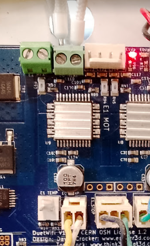
the two thicker white wires do eventually appear at the extruder, in different colour(s)As for fancy bed levelling I'm happy to stick with the two Z motors in synch and if needed it is a simple matter of using a test block at each side to 're-level' if they get out of synch, so aye 'one step at a time'
Alan
-
@Bridge-Of-Don
I am happy to report that we have today successfully manged to print off a small 'cube'.
We still need to fine tune the heaters both on control (to prevent overshoot) and actual temperature but at least it functions.
We used the 'AstroPrint' web based slicing option and downloaded the G-codes to the PC then 'uploaded' them to DWC, maybe not the most elegant of solutions but it works.
We like the ability to 'fine tune' the slicing within the 'AstroPrint' as hopefully we will learn as we go-along.I'm away again for a week, then home then away, so will have nowt to report for a little while.
-
undefined Phaedrux marked this topic as a question 27 Jun 2024, 21:44
-
undefined Phaedrux has marked this topic as solved 27 Jun 2024, 21:44