Mosfet issue? chamber heater in E1heat supplying 24V when off
-
I am using a Duet 2 Ethernet motherboard with RepRap V3.3 and currently have a hotend connected to E0heat (working properly) and a bed heater (requires 120V AC) connected to the bed heat terminal with an SSR (also working properly).
Recently, I added on a chamber heater and read the Duet Documentation for connecting a chamber heater during setup. My chamber heater is a 1000W ceramic air heater that can use 110V or 220V AC. That said, I set up the chamber heater to work with AC mains power through an SSR to the motherboard.
First, I wanted to try connecting the chamber heater to E1Heat (an extra extruder terminal) via its SSR. The duet documentation states that you can do this if your chamber heater uses the same voltage requirement as the board. The motherboard requires 24V DC, of course, and as I mentioned, the chamber heater requires 110V or 220V AC. That said, they are not the same. I knew this initially, though I wanted to test the chamber with a lower voltage input from this terminal to see if I could get it to work properly when directly connected to the board.
As a result of this test, every time I turn on the board and the chamber heater is plugged into AC mains power, the heater immediately starts heating and will not stop until it is unplugged from the mains (even though it is OFF on the interface and has not been activated). I later found that the E1Heat terminal I plugged it into from its SSR was receiving 24V no matter what mode I set (OFF, ON, or STANDBY) and the light showing that extruder heater as "ON" stays lit as well. Even when the chamber heater is not plugged into AC mains the motherboard still sends 24V to this terminal.
Finally, here's my questions on all this:
-
From all of my searching on this issue, it seems most likely that I have messed up or blown my MOSFET for this extruder terminal, E1Heat. Can anyone confirm whether it is completely blown or if it is salvageable? Could I reset the board and see if it goes back to normal?
-
Is it not possible for me to connect the chamber to the board this way? If so, what other method makes the most sense based on its requirements? I'm doing my best to try to run all my heaters on this one board....
If anyone has any recommendations at all I would really appreciate your thoughts!
-
-
@Charily_Antics_343 yes, it sounds like the mosfet is blown. It can be replaced by someone who is capable of soldering components.
Regarding the voltage comment -- that's only relevant for heaters directly driven by the board; if you drive SSRs they will be driven with VIN no matter whether the heater runs 110V or 220V or whatever.
The good news is that since you use an SSR, you should be able to use a PWM capable IO to drive the SSR as well since they usually can take something between 5V and 30V as input -- check your SSR for actual specs. Note that cheap SSRs are often counterfeits which may not actually meet the documented specs,.
-
@oliof After looking at the diagram of the Duet 2 Ethernet motherboard multiple times, I cannot pinpoint where the MOSFET for E1heat is.... Would you be able to point this out for me? I should be able to replace it myself. (Apologies for such a basic question here.)
Also, is there a PWM capable IO on this motherboard you think I might be able to use? Or would this require an additional board? My SSR is rated for 3-32V DC input. I am using a Crydom D2425 which I trust is working correctly. (I am using the same SSR for the bed and it hasn't had any issues.)
Thank you so much for your recommendations!
-
@Charily_Antics_343 said in Mosfet issue? chamber heater in E1heat supplying 24V when off:
Also, is there a PWM capable IO on this motherboard
Yes the hotend heater and fan outputs can be configured as heater outputs to switch an SSR. Just choose the pin name of the output you want to use.
-
@Charily_Antics_343
You can find the schematic here.
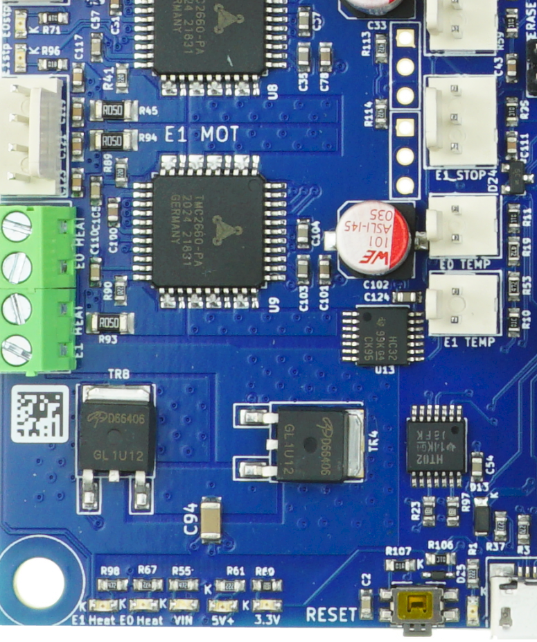
It is TR8.
-
@Charily_Antics_343 how did you connect the SSR control terminals to the E1 output? The E1 output has a pin that is permanently connected to VIN (which in your case is 24V) and a pin that is switched to ground by the mosfet. So you can connect the 3 to 32V SSR control terminals to those pins (making sure you get the polarity correct).
If the E1 mosfet is blown then the red LED that indicates power is being supplied to the output will be lit permanently.
-
This post is deleted!