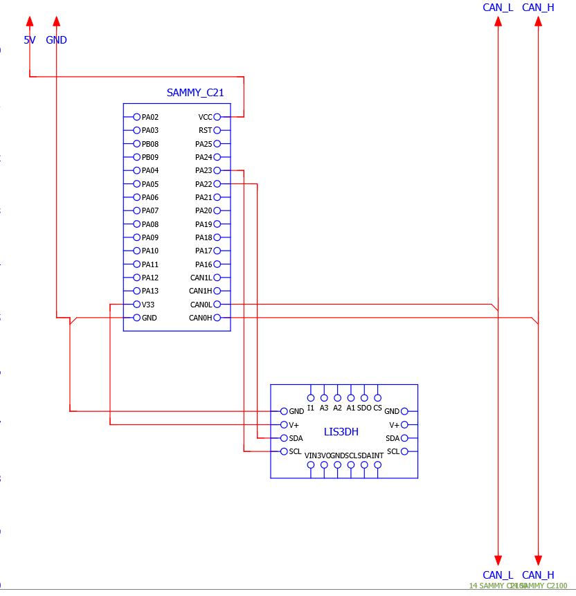
Adafruit LIS3DH and Sammy-C21
-
Hello,
I ordered both of these boards and have read through these two pages:
https://docs.duet3d.com/en/User_manual/Connecting_hardware/Sensors_Accelerometer
and
https://docs.duet3d.com/Duet3D_hardware/Duet_3_family/Using_the_Sammy-C21_development_board_with_Duet_3But I'm not seeing how exactly to wire these two boards together.
Here's what I think I understand so far:
On the Sammy-C21:
VCC - connected to a 5V output from a Duet board
GND - connected to a ground pin on a Duet board
CAN0 L - connected to Duet CAN_L (out)
CAN0 H - connected to Duet CAN_H (out)
CAN1 L - one side of a 120 ohm resistor
CAN1 H - the other side of the 120 ohm resistor
PA13 - ?
PA16-18 ?
PA21-23 - probably unused?
button1 - probably unused?On the LIS3DH
VIN - 5V connected to Sammy-C21
GND - connected to Sammy-C21 ground
SDO - ?
SCL - ?
SDA - ?
remaining pins probably not used?Thanks
-
@p8blr if you will be connecting a LIS3DH or LIS2DW accelerometer to the SAMMYC21 then it's easiest if you run the SAMMYC21 from 3.3V not 5V, so that the I2C bus runs at 3.3V. So I suggest that you don't bypass the 3.3V regulator. You can power the SAMMYC21 from a USB power supply, at least initially.
Regarding the CAN connections, see https://docs.duet3d.com/en/Duet3D_hardware/Duet_3_family/Using_the_Sammy-C21_development_board_with_Duet_3#connecting-the-sammy-c21-to-a-duet-3-system. You don't need to do anything with the unused CAN1 port.
The LIS will run in I2C mode, therefore the SDO pin should be left not connected. The SCL and SDA pins on the SAMMYC21 are as listed at https://docs.duet3d.com/en/Duet3D_hardware/Duet_3_family/Using_the_Sammy-C21_development_board_with_Duet_3#features-of-the-standard-firmware-binary. Likewise the button.
-
@dc42 If the SammyC21 is the last device in my series, how will the CAN bus get terminated? Would I need to solder a 120 ohm resistor to CAN0 L and CAN0 H, or could I terminate it elsewhere by using a termination jumper on one of my other duet boards - in other words does the terminating resistor have to be at the very end of the chain?
So to be clear, you're saying the only connections coming from the LIS3DH will be 3.3V, ground, SCL, and SDA?
-
@p8blr yes, the terminating resistor goes at the end of the chain
-
@p8blr You can wire the SammyC21 as a 'stub' off the main CAN bus, and terminate the bus on another board. See the 'stubs' section under https://docs.duet3d.com/en/User_manual/Machine_configuration/CAN_connection#wiring-scheme
Ian
-
M955 P124.0Returns: Accelerometer 124.0 type LIS3DH with orientation 12 samples at 1344Hz with 10-bit resolution
But when I record the motion profile I get:
Error: M956: Failed to start accelerometer data connection: INT1 error
I wired what @dc42 mentioned regarding the I2C mode, but the instructions aren't clear on [THIS](link url) page as to what interrupt pin I need to use.
Help please?
-
@p8blr you need to connect the LIS3DH INT pin to PA13. See the table at https://docs.duet3d.com/Duet3D_hardware/Duet_3_family/Using_the_Sammy-C21_development_board_with_Duet_3#features-of-the-standard-firmware-binary.
-
@dc42 Thanks, connecting the int pin fixed it.
For anyone else reading this thread in the future, you need 5 wires from a LIS3DH to a SAMMY C21.
GND - GND
V33 - V+
PA22 - SDA
PA23 - SCL
PA13 - INT -
undefined dc42 marked this topic as a question 12 Oct 2024, 15:31
-
undefined dc42 has marked this topic as solved 12 Oct 2024, 15:31
