My Second build (in progress)
-
@Dad003 You can simplify construction and probably reduce mass by using rectangular aluminum tubing to make the two pulley blocks at the ends of the axis. You can use it for motor mounts, too.
If you bolt the t-slot pieces directly to each other you won't need all those corner braces. Tap the ends of the inside t-slot pieces, and drill tool-access holes at appropriate locations in the outside t-slot pieces. You can use button head cap screws with washers in the slots to connect two pieces together. This assumes that the ends of the pieces are cut/milled square. See: https://www.youtube.com/watch?v=HfcXjYWw5UQ
-
@mrehorstdmd said in My Second build (in progress):
@Dad003 You can simplify construction and probably reduce mass by using rectangular aluminum tubing to make the two pulley blocks at the ends of the axis. You can use it for motor mounts, too.
If you bolt the t-slot pieces directly to each other you won't need all those corner braces. Tap the ends of the inside t-slot pieces, and drill tool-access holes at appropriate locations in the outside t-slot pieces. You can use button head cap screws with washers in the slots to connect two pieces together. This assumes that the ends of the pieces are cut/milled square. See: https://www.youtube.com/watch?v=HfcXjYWw5UQ
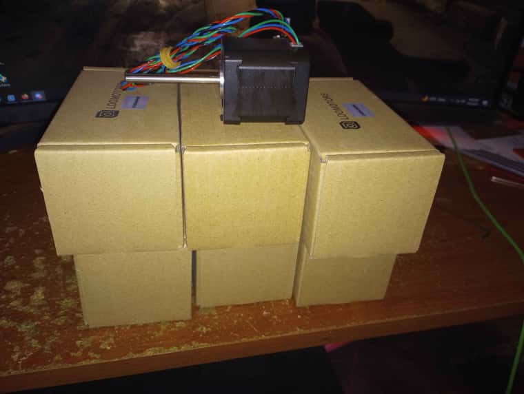
ill take that in consideration , but my plan here is to have everything out of aluminum plate , water jet cut since i dont have the equipment to do a lot of drilling or machining , the machine i would need for that at work never has the right setup on it lol , with that process i can easily had a lots of cut to lighten everything since it all on mgn9c block , him still at early design anyway just slowly designing and then printing things and see how it look like , knowing myself i will most likely fill up a whole box of parts again until final design .
still not sure about what kind of probe i will use becasue of the heated chamber been thinking of a klicky probe since there are high temp switch
-
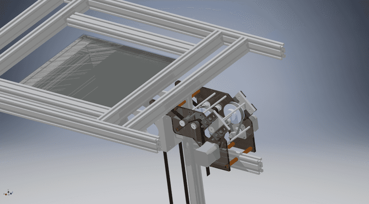
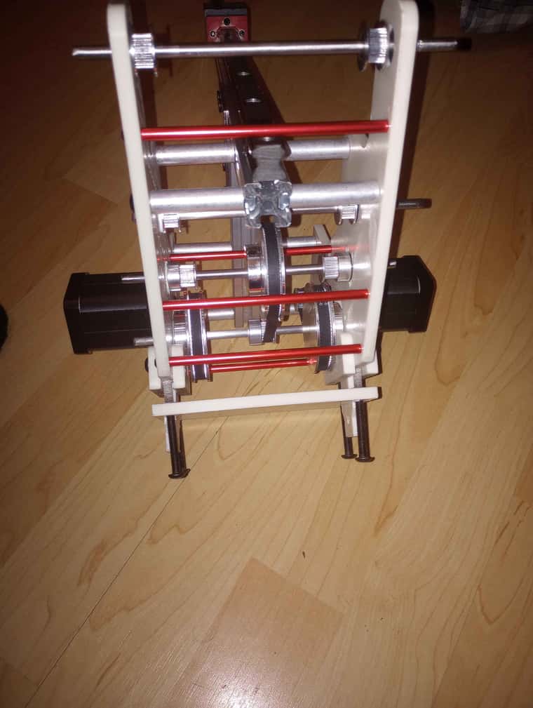
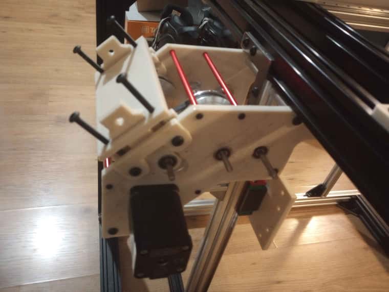
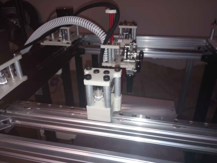
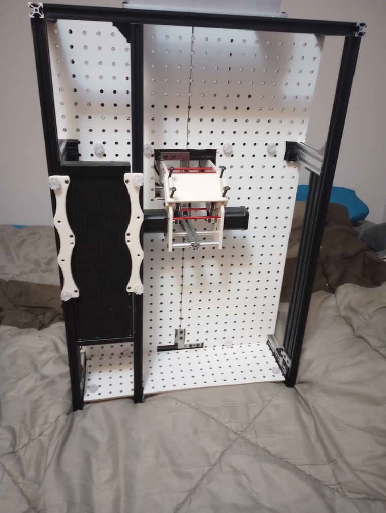
Slowly simplifying every component as well, working in my z axis system with belt , current printer use 20>60-20>60-20 this for 1380 step , this one will use 20>80-20>80-20 for over 2500 step with a .9 stepper motor , and the holding torq is.so good that with no power bed doesn't fall down .
-
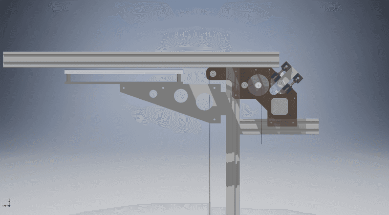
redesigned my Z axis belt system one more time
-
@Dad003 One of these will make your life much easier. The 30:1 reduction enables it to lift very heavy beds, and it doesn't move when the motor is disabled, allowing restart of prints in the event of a power failure. It doesn't require brakes, additional wiring, or additional configuration. Just treat the motor like a normal stepper. I used 60 tooth pulleys on the shaft to get 20 um per full step from the motor. I've been using it for my 695 mm Z-axis about 7 years without any problems. The gear quality is very high, so there are no gear induced artifacts in the z-axis of prints.
-
@mrehorstdmd said in My Second build (in progress):
@Dad003 One of these will make your life much easier. The 30:1 reduction enables it to lift very heavy beds, and it doesn't move when the motor is disabled, allowing restart of prints in the event of a power failure. It doesn't require brakes, additional wiring, or additional configuration. Just treat the motor like a normal stepper. I used 60 tooth pulleys on the shaft to get 20 um per full step from the motor. I've been using it for my 695 mm Z-axis about 7 years without any problems. The gear quality is very high, so there are no gear induced artifacts in the z-axis of prints.
Do you have a link to this particular one ?
My pulley system doesn't drop the bed either , I've tested it and you need over 10 pound on the table to even make it move
-
@Dad003 click on "one of these" in the post above. That guy has been selling the things via ebay for many years.
Your design may work, but look at all the parts and space required. The worm gear box with attached motor is as simple as it gets. -
@mrehorstdmd yea i understand that , but still after looking at that price , most of my component are readily available on amazon , other than the 2 side plates that need to be water jet cut for the final version it cost a fraction of that worm gear setup .
-
@Dad003 I thought you were trying to simplify the design. Never mind.
-
@mrehorstdmd kinda but I want to keep cost down as well . From my early calcul this will be an expansive build about 3000 to 5000 $ at least . Depending of material to enclose the full printer.
-
This post is deleted! -
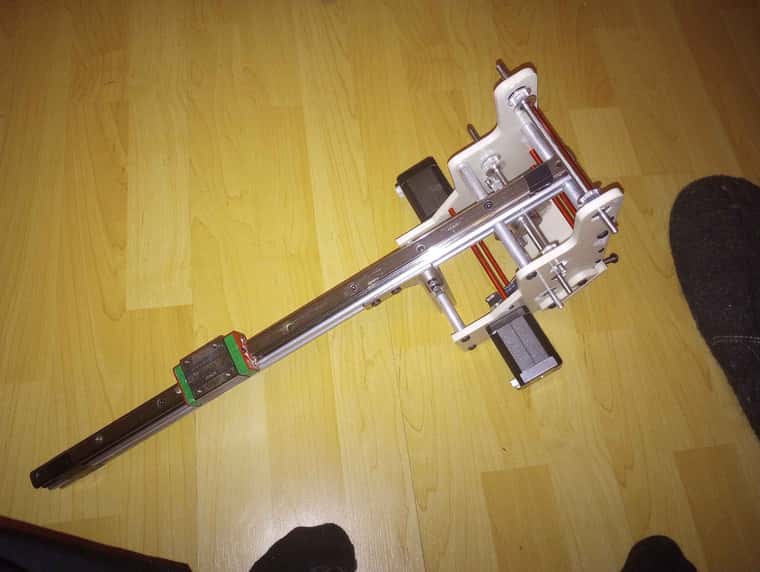
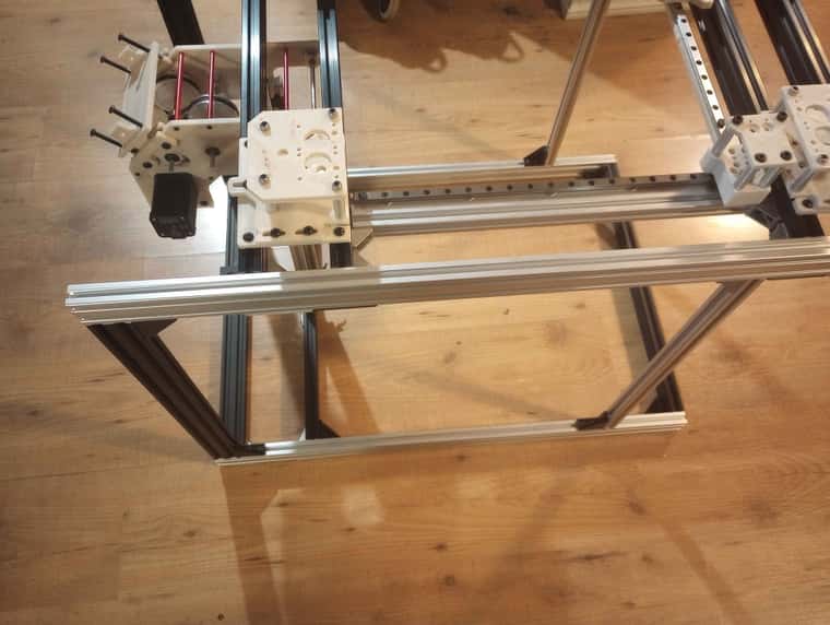
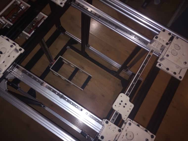
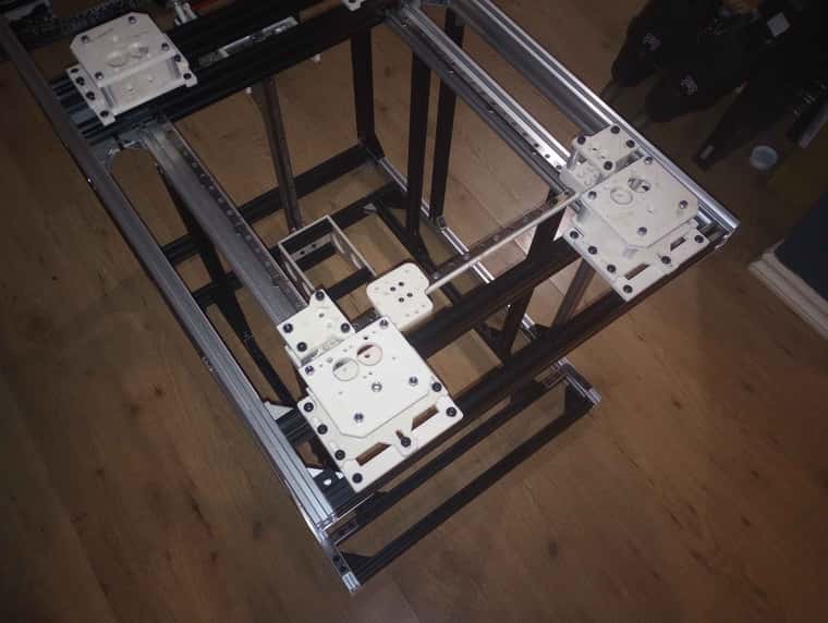
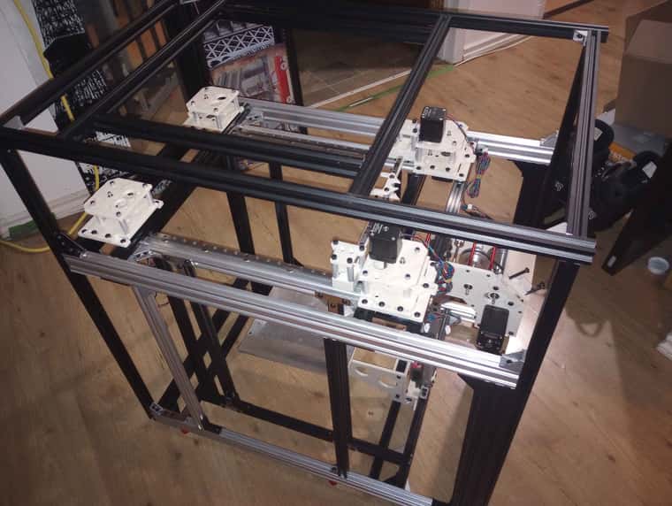
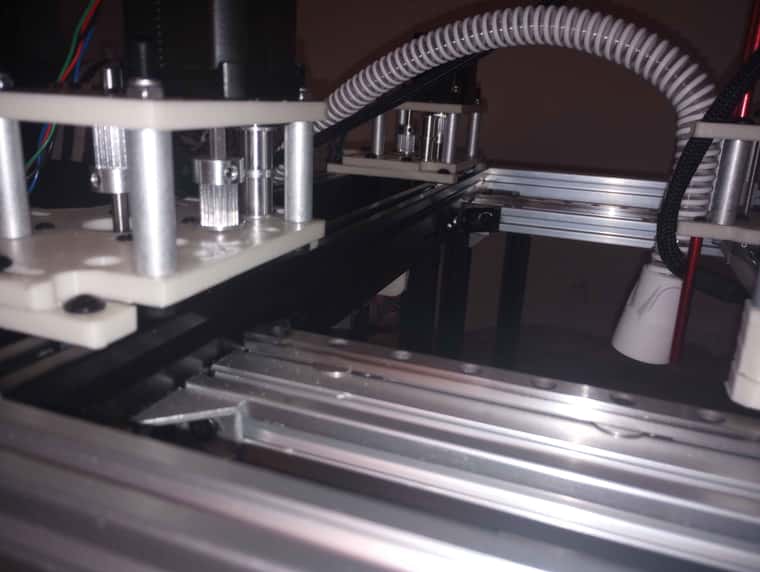
Z axis assembled, i have more aluminum extrusion on the way so i should be able to fully assemble the frames . still have many part to prints , to test
 ,
, -
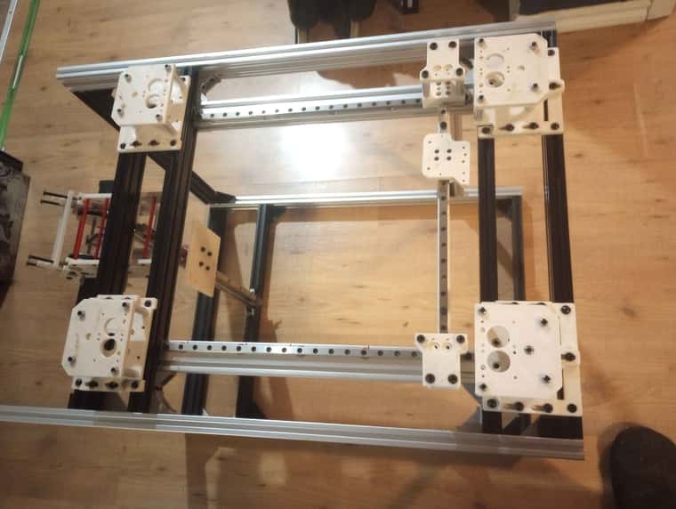
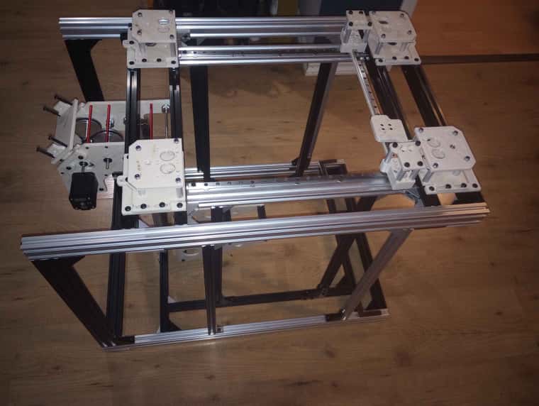
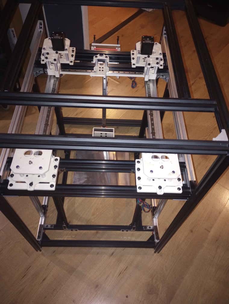
frame 1/2 assembled .
-
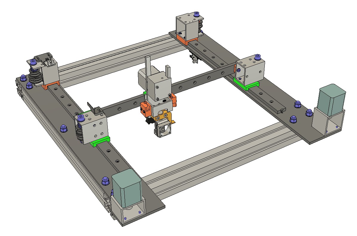
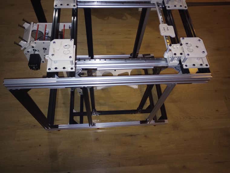
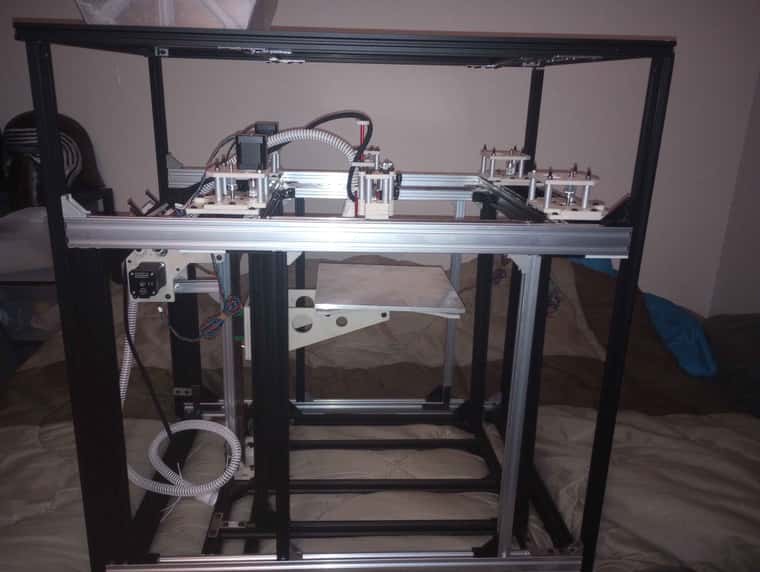
main frame of the beast is mostly done , i need to add a bar or 2 in one spot and that will be it for that .
-
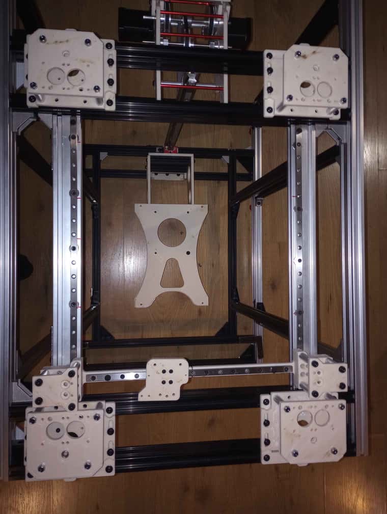

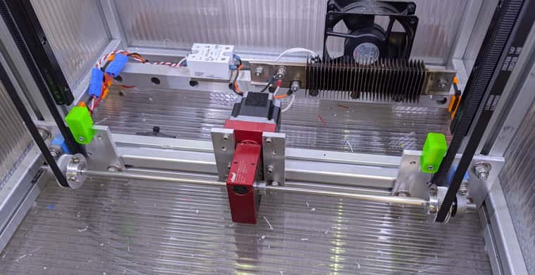
250mm print bed it is , it will use a silicon heater from keenovo with a voron cutout. Need to reprint gantry , did some change to make it smaller lighter .
-
i Went with the LDO , super power HT for my build , they have nice spec for a quick machine and 180C temp max and since they will sit outside the heated chamber we should have a good margin. pick up the 55mm shaft version as well so i could add an extra bearing to support the end .
-
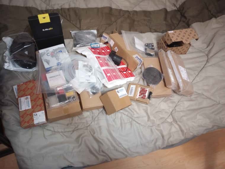
slowly been working on it , here a little update , ive been slowly ordering part, thinking and designing more things .
-
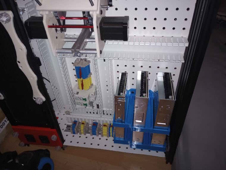
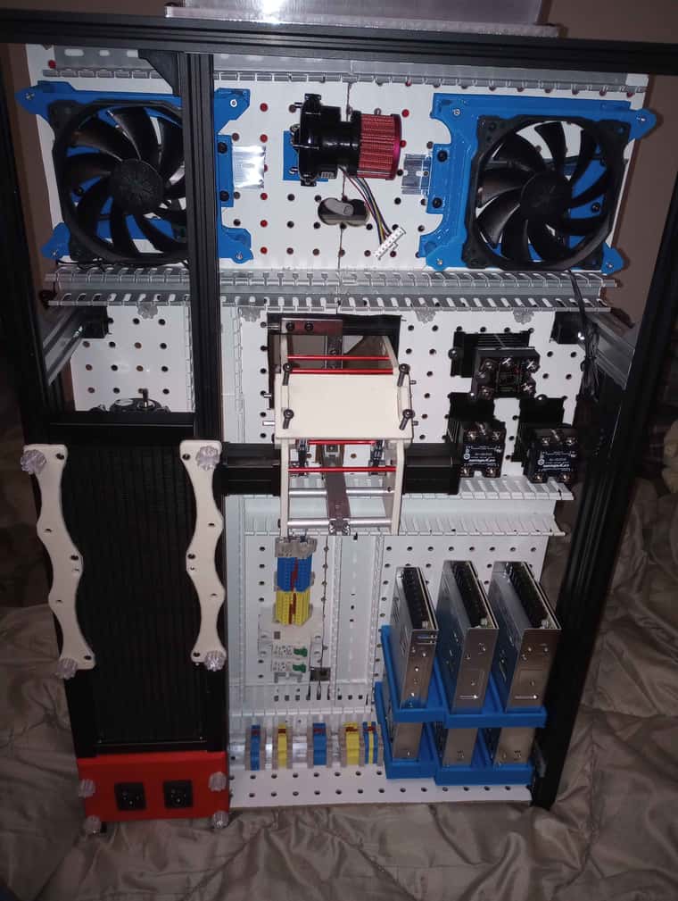
well him still slowly building this , still have to buy a duet 3 and an expansion board , but currently in canada there is no duet 3 6hc in stock anywhere , and i have to buy silicon heater for heated bed and heated chamber . anything else is already here , 12v psu for all the fan and water pump , 24volt for the expansion board and hotend , and 48v for the main mobo for xy axis. i need to print myself some riser for the din rail so they sit higher a bit so they are easier to wire .
-
well i think i got my layout all done now , had to go with some smaller cable tray for the top since i was a bit space restricted but it should be enough . fun part to come is to wire everything which is gonna be interesting lol , main duet will be on the right and expansion board on the left . both will have a 120mm fan to cool off the mobo . on top of the 3x120 sucking air for the radiator .
-
well here another little update , duet 3 6hc has been ordered , only things left is the expansion board and a few minor things to buy to get this baby online for some test .
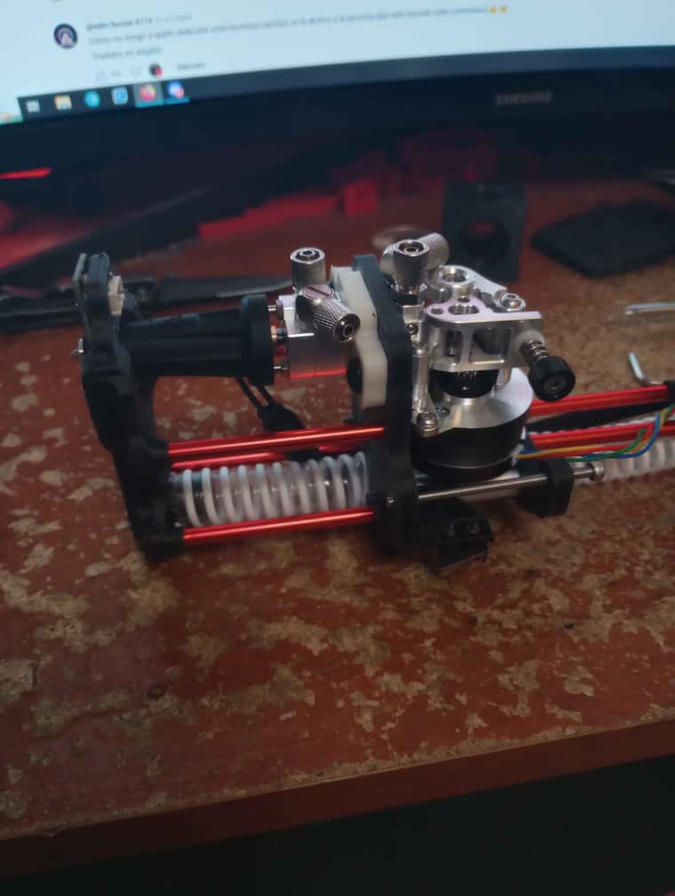
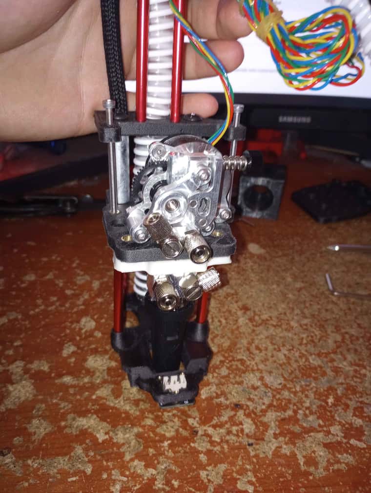
hot end assembly minus water cooled loop and a few things. ended up going for a klicky for probe . it is sitting at the front of the air duct close of the nozzle .