Duet3D Logo Duet3D
    • Tags
    • Documentation
    • Order
    • Register
    • Login

    My Second build (in progress)

    Scheduled Pinned Locked Moved
    My Duet controlled machine
    6
    55
    3.2k
    Loading More Posts
    • Oldest to Newest
    • Newest to Oldest
    • Most Votes
    Reply
    • Reply as topic
    Log in to reply
    This topic has been deleted. Only users with topic management privileges can see it.
    • mrehorstdmdundefined
      mrehorstdmd @Dad003
      last edited by

      @Dad003 I thought you were trying to simplify the design. Never mind.

      Dad003undefined 1 Reply Last reply Reply Quote 0
      • Dad003undefined
        Dad003 @mrehorstdmd
        last edited by

        @mrehorstdmd kinda but I want to keep cost down as well . From my early calcul this will be an expansive build about 3000 to 5000 $ at least . Depending of material to enclose the full printer.

        mrehorstdmdundefined fcwiltundefined 2 Replies Last reply Reply Quote 0
        • mrehorstdmdundefined
          mrehorstdmd @Dad003
          last edited by

          This post is deleted!
          1 Reply Last reply Reply Quote 0
          • Dad003undefined
            Dad003
            last edited by

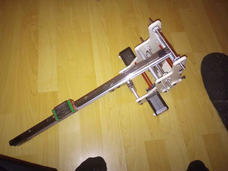
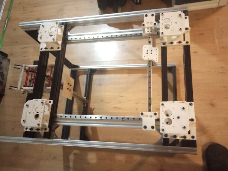
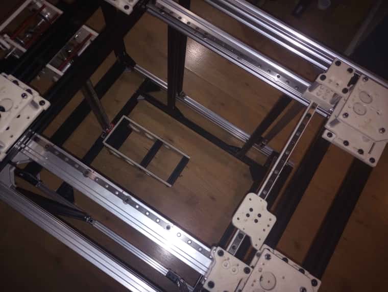
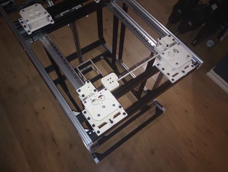
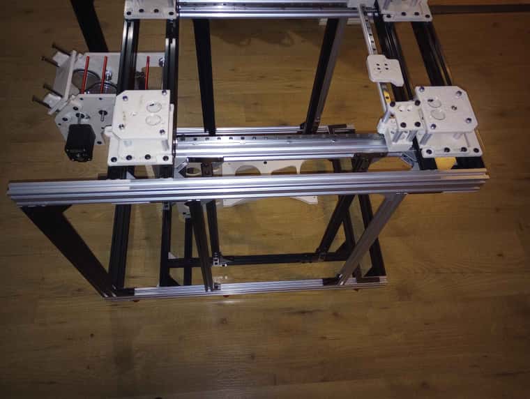
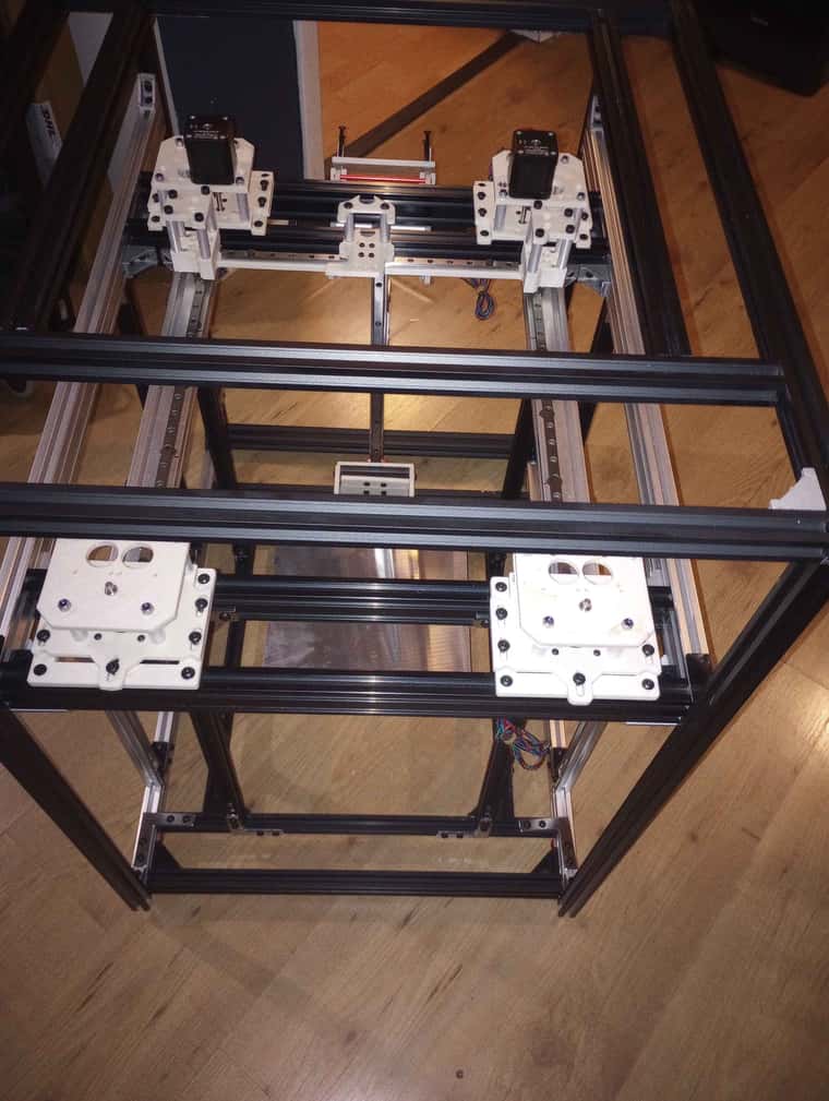
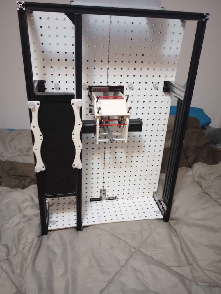
            Z axis assembled, i have more aluminum extrusion on the way so i should be able to fully assemble the frames . still have many part to prints , to test

            IMG_20240825_002244130.jpg IMG_20240825_002259059.jpg ,

            1 Reply Last reply Reply Quote 0
            • Dad003undefined
              Dad003
              last edited by

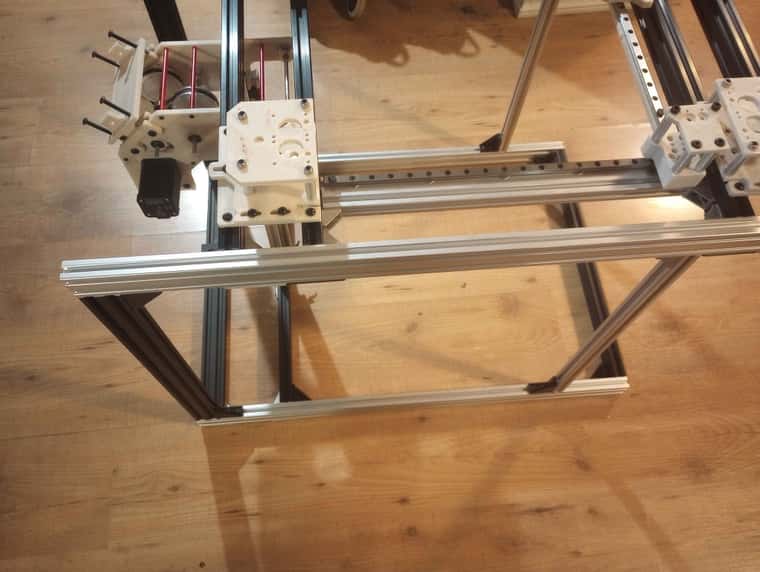
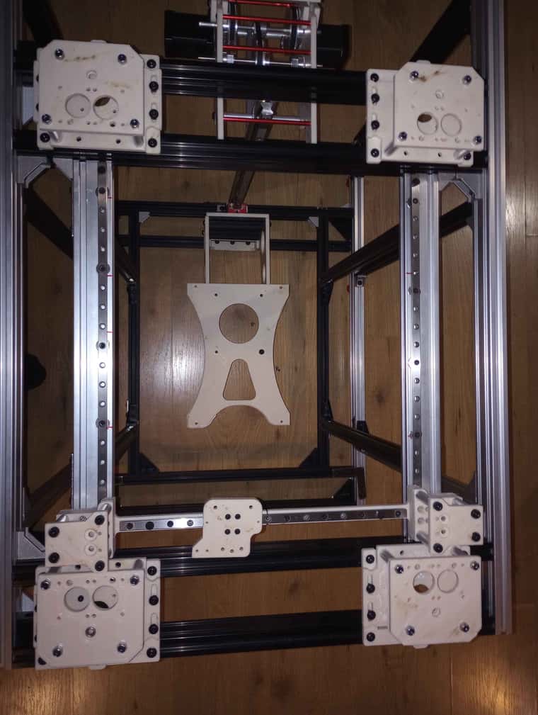
              frame 1/2 assembled .

              IMG_20240825_164124459.jpg IMG_20240825_164135690.jpg IMG_20240825_164115181.jpg

              1 Reply Last reply Reply Quote 0
              • Dad003undefined
                Dad003
                last edited by

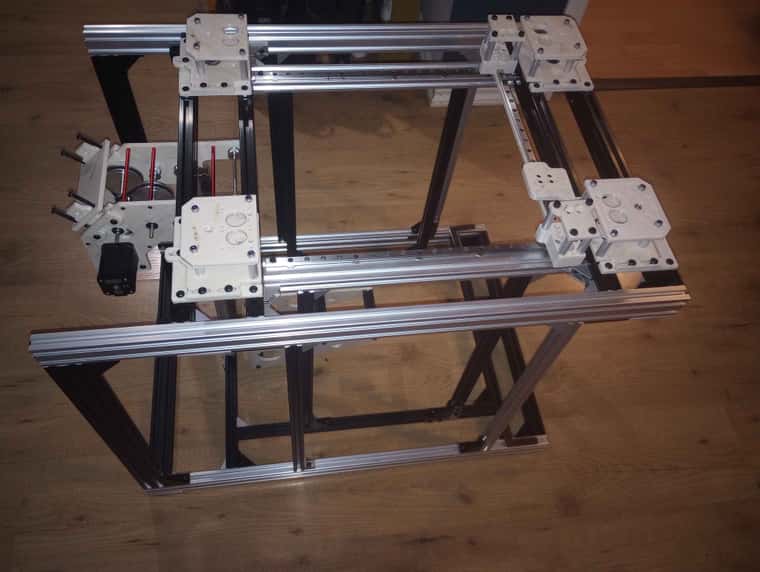
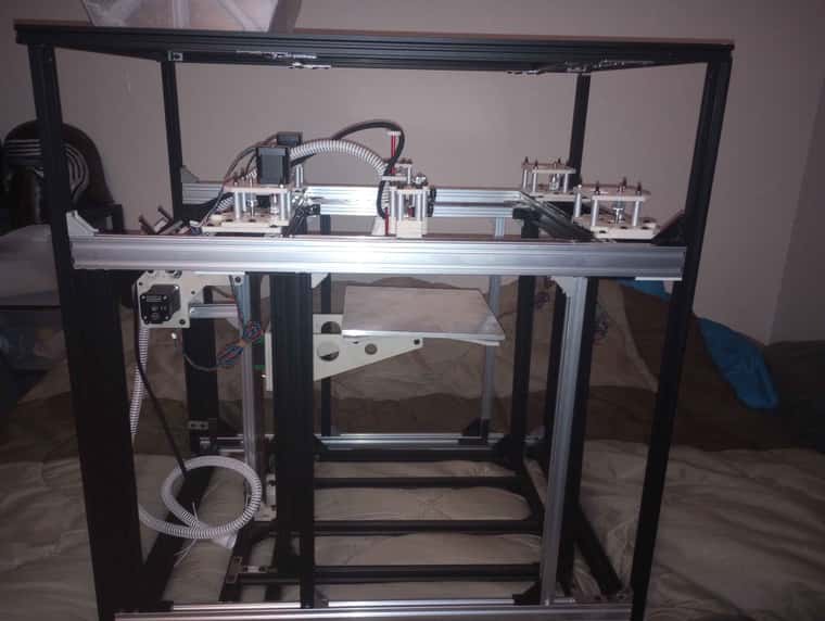
                main frame of the beast is mostly done , i need to add a bar or 2 in one spot and that will be it for that .

                IMG_20240826_214406473.jpg IMG_20240826_214353814.jpg IMG_20240826_214418960.jpg

                1 Reply Last reply Reply Quote 0
                • Dad003undefined
                  Dad003
                  last edited by

                  IMG_20240830_071051157.jpg IMG_20240830_071039737.jpg IMG_20240830_071051157.jpg

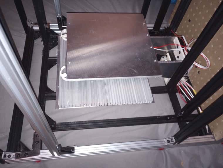
                  250mm print bed it is , it will use a silicon heater from keenovo with a voron cutout. Need to reprint gantry , did some change to make it smaller lighter .

                  1 Reply Last reply Reply Quote 1
                  • Dad003undefined
                    Dad003
                    last edited by

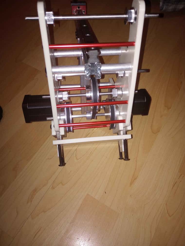
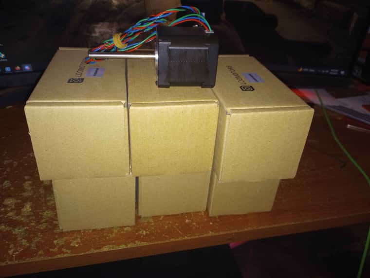
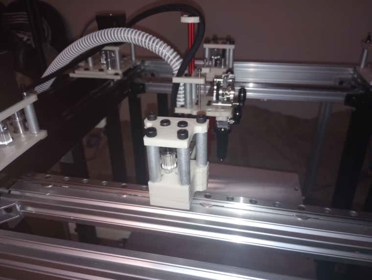
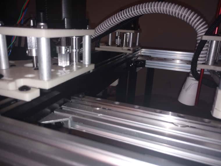
                    i Went with the LDO , super power HT for my build , they have nice spec for a quick machine and 180C temp max and since they will sit outside the heated chamber we should have a good margin. pick up the 55mm shaft version as well so i could add an extra bearing to support the end .

                    IMG_20240909_215057957.jpg IMG_20240909_224905446.jpg IMG_20240909_224944366.jpg

                    1 Reply Last reply Reply Quote 0
                    • Dad003undefined
                      Dad003
                      last edited by

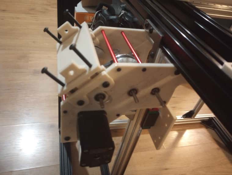
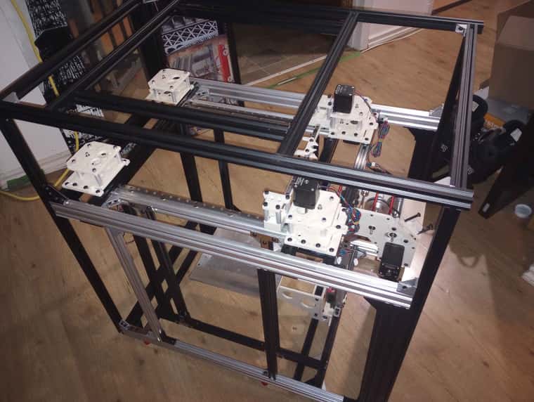
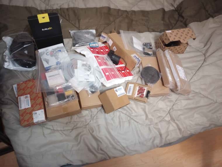
                      slowly been working on it , here a little update , ive been slowly ordering part, thinking and designing more things .

                      IMG_20241031_202912877.jpg IMG_20241031_202620263.jpg IMG_20241031_202632510.jpg

                      1 Reply Last reply Reply Quote 2
                      • Dad003undefined
                        Dad003
                        last edited by

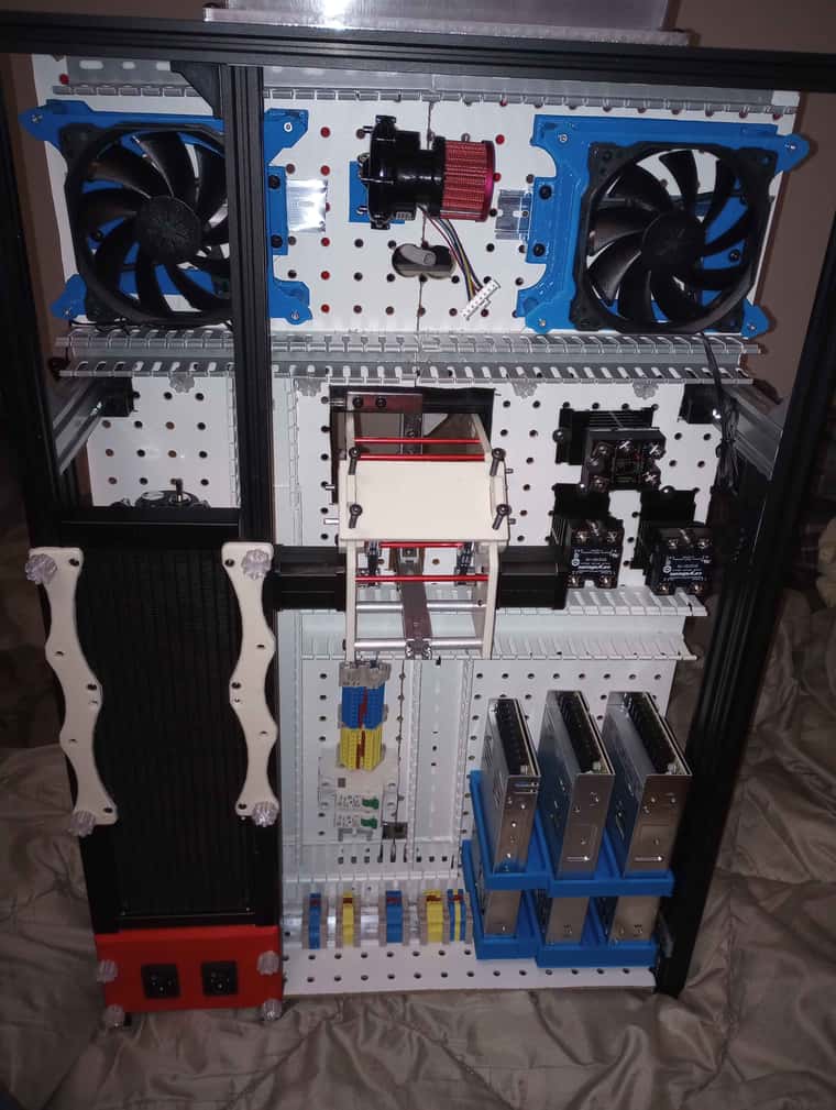
                        well him still slowly building this , still have to buy a duet 3 and an expansion board , but currently in canada there is no duet 3 6hc in stock anywhere , and i have to buy silicon heater for heated bed and heated chamber . anything else is already here , 12v psu for all the fan and water pump , 24volt for the expansion board and hotend , and 48v for the main mobo for xy axis. i need to print myself some riser for the din rail so they sit higher a bit so they are easier to wire .

                        IMG_20241226_182234719.jpg IMG_20241224_153822832.jpg IMG_20241224_214630934.jpg

                        1 Reply Last reply Reply Quote 1
                        • Dad003undefined
                          Dad003
                          last edited by

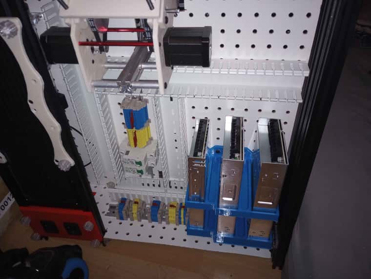
                          well i think i got my layout all done now , had to go with some smaller cable tray for the top since i was a bit space restricted but it should be enough . fun part to come is to wire everything which is gonna be interesting lol , main duet will be on the right and expansion board on the left . both will have a 120mm fan to cool off the mobo . on top of the 3x120 sucking air for the radiator .

                          IMG_20241228_161145754.jpg

                          1 Reply Last reply Reply Quote 0
                          • Dad003undefined
                            Dad003
                            last edited by

                            well here another little update , duet 3 6hc has been ordered , only things left is the expansion board and a few minor things to buy to get this baby online for some test .
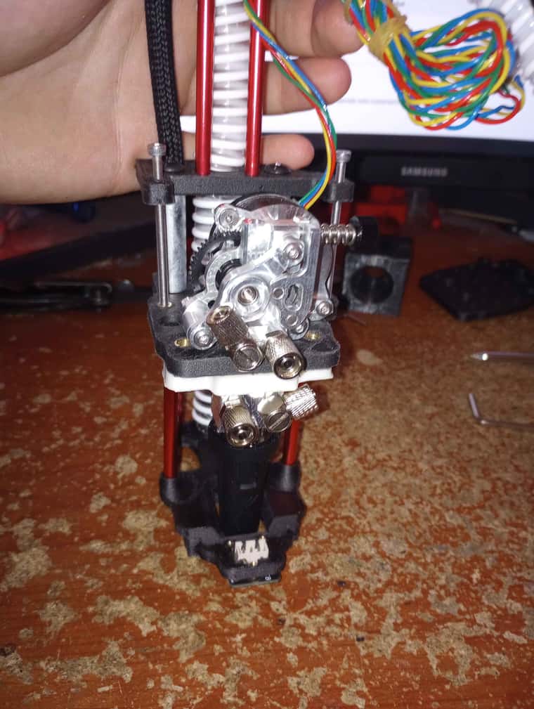
                            hot end assembly minus water cooled loop and a few things. ended up going for a klicky for probe . it is sitting at the front of the air duct close of the nozzle .

                            IMG_20250118_160800667_HDR.jpg IMG_20250118_160830560.jpg

                            1 Reply Last reply Reply Quote 0
                            • Dad003undefined
                              Dad003
                              last edited by

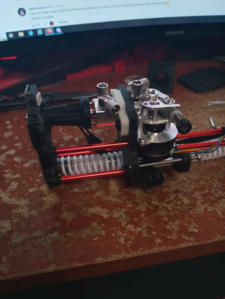
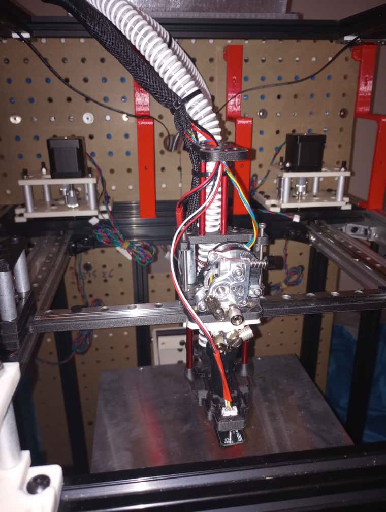
                              started to work on some of my wiring a bit mostly for the hotend so far ,

                              IMG_20250121_211437410.jpg

                              1 Reply Last reply Reply Quote 1
                              • Dad003undefined
                                Dad003
                                last edited by

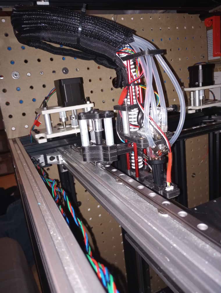
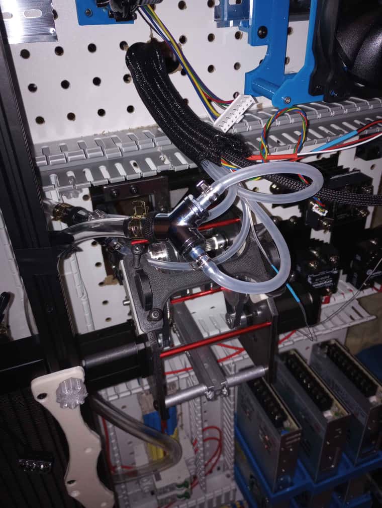
                                Well my duet 3 6hc 1.02 finally arrived now waiting for the expansion board to show up and i will be able to finalize the wiring and fire this things up soon and do some test , my original plan was to run a single water cooled loop to the extruder and hotend but the tubing couldn't make the bend , so decided to use a Y splitter in the back that come from a bigger tube for the loop and split in 2 . than split back in 1 .

                                IMG_20250203_221317491.jpg

                                IMG_20250129_193644624.jpg

                                T3P3Tonyundefined cosmowaveundefined 2 Replies Last reply Reply Quote 0
                                • T3P3Tonyundefined
                                  T3P3Tony administrators @Dad003
                                  last edited by

                                  @Dad003 wow that looks like a lot of water. Is that water cooling form an existing design? I found when messing with watercooled hot ends years ago that very little water was actually needed as its such an efficient conductor of heat.

                                  www.duet3d.com

                                  Dad003undefined 1 Reply Last reply Reply Quote 1
                                  • Dad003undefined
                                    Dad003 @T3P3Tony
                                    last edited by

                                    @T3P3Tony it a Vzbot extruder and hotend , water cooled version , but the rest is just my own idea , like I said I wanted to do a single loop but couldn't have both cooled , the ultimate Goal is to have this things in a 80-100c heated chamber for Polycarbonate , will it stay like this I don't know , I have lots of testing to do .

                                    All pass throw a 360mm rads to cool off . Honestly can't wait to have this monster power on lol

                                    1 Reply Last reply Reply Quote 0
                                    • cosmowaveundefined
                                      cosmowave @Dad003
                                      last edited by

                                      @Dad003 said in My Second build (in progress):

                                      but the tubing couldn't make the bend

                                      Eventually, a spring over the tube helps against kinking?
                                      But this works only, when the tube isn't to stiff.

                                      Mankati FSXT+, DeltaTowerV2, E3D MS/TC

                                      Dad003undefined 1 Reply Last reply Reply Quote 0
                                      • Dad003undefined
                                        Dad003 @cosmowave
                                        last edited by

                                        @cosmowave I didn't think of that .

                                        1 Reply Last reply Reply Quote 0
                                        • Dad003undefined
                                          Dad003
                                          last edited by

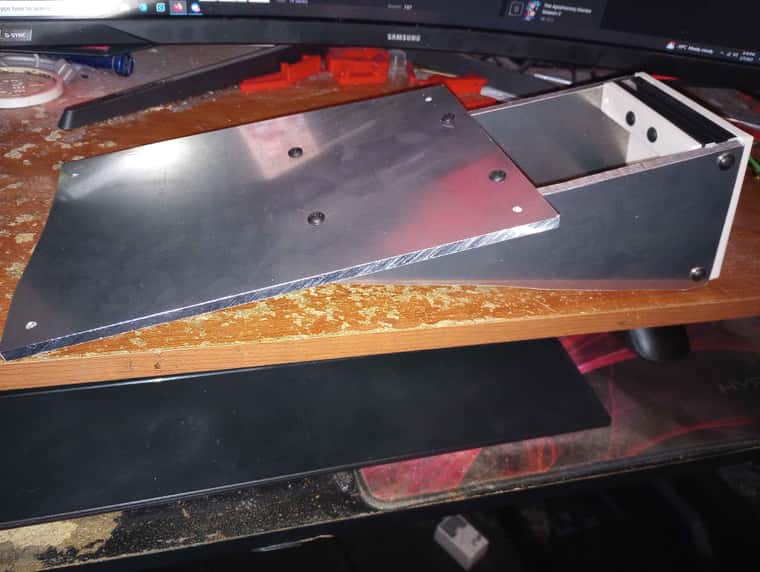
                                          swapped my 3d printed bed base for some basic aluminum parts , they are a bit crude lol i have limited tool at my hand for that but they will be good enough .

                                          IMG_20250207_202859524.jpg IMG_20250207_201045456.jpg IMG_20250207_201552357.jpg

                                          mrehorstdmdundefined 1 Reply Last reply Reply Quote 0
                                          • mrehorstdmdundefined
                                            mrehorstdmd @Dad003
                                            last edited by

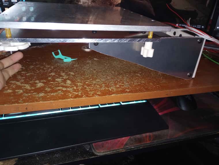
                                            @Dad003 That looks like a piece of cast tooling plate. That means it is flat. 3 points define a plane, not 4, so trying to tram with 4 screws is not a great idea.

                                            You might want to look into a kinematic mount for that bed plate. As it heats it will expand. That means something is going to have to flex and that means it will shift out of tram. A kinematic mount has 3 bed support points and just two tramming adjustments. It allows the bed to expand without causing anything to flex so doesn't go out of tram.

                                            Dad003undefined 1 Reply Last reply Reply Quote 0
                                            • First post
                                              Last post
                                            Unless otherwise noted, all forum content is licensed under CC-BY-SA