Inconsistent Trigger Height
-
Hi, I can't get consistent trigger heights for my delta printer and it throws up constant errors when auto-calibrating and auto-bed levelling. It does not print a consistent first layer.
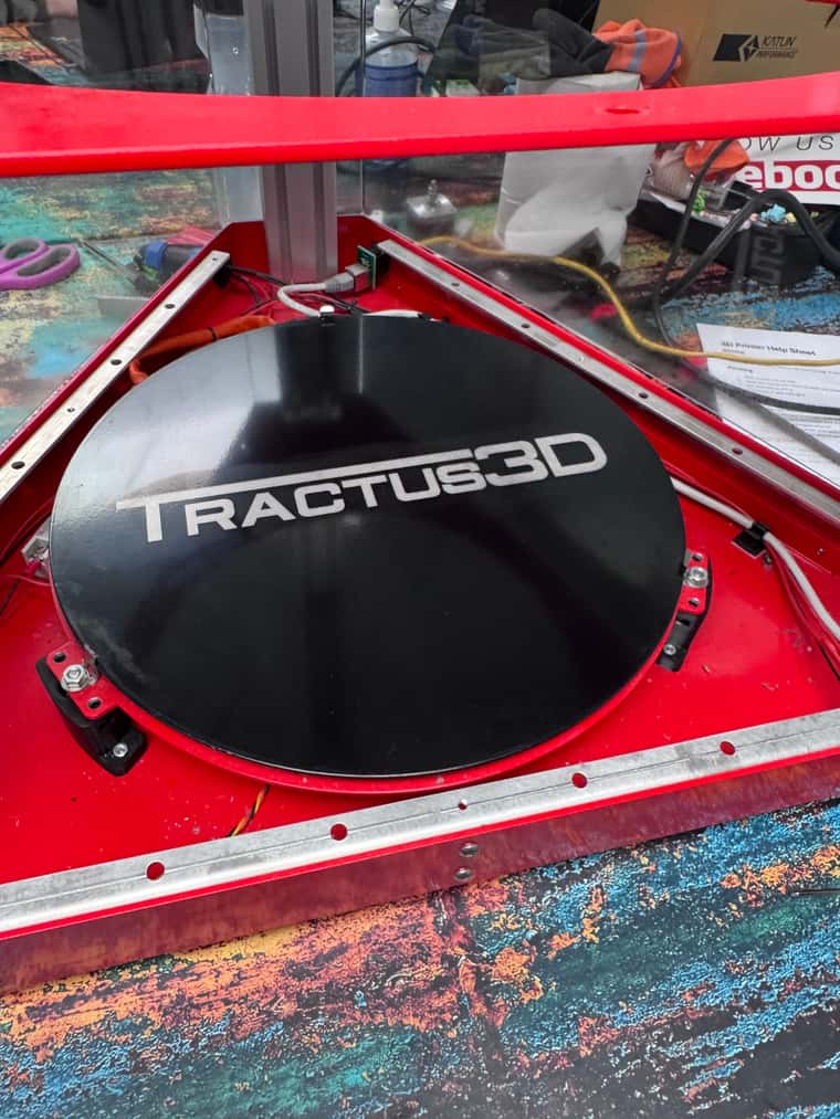
Printer: Tractus t1250 delta printer
Firmware:
-
RepRapFirmware for Duet 2 WiFi/Ethernet FIRMWARE_VERSION: 3.5.1 ELECTRONICS: Duet Ethernet 1.02 or later FIRMWARE_DATE: 2024-04-19 14:40:46
-
Paneldue 1.21.3
Hardware:
-
Duet2 v1.03
-
E3d v6 hot end, hemera boden extruder
I was following the calibration guide for delta printers and got to the auto-calibration step. When I got to the step to find the z-trigger height I could not get a consistent reading. I am not sure if this is hardware-related or software-related.
I have a range of measurements from -0.283mm to - 0.471mm. But each reading is different and a random number in this rang
e.I am not sure what to do and what to check. So far I have:
-
Tried doing it hot and cold and I got the same inconsistencies.
-
Checked that the carriage wheels move freely.
-
I am not sure how to check the motor current.
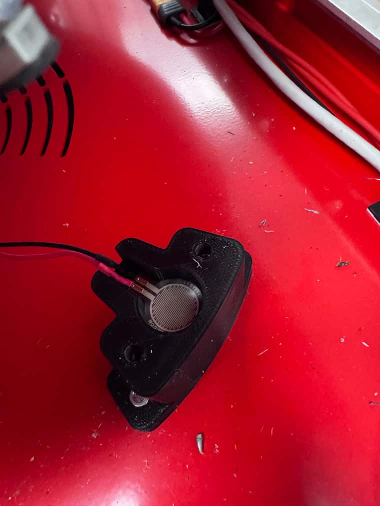
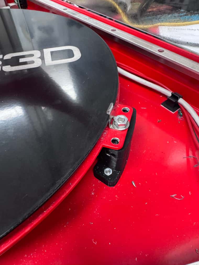
But it could be due to how the bed probe system is set up, I am not entirely sure how it works. It uses the nozzle so I assume it is a pressure sensor as it is a glass bed.
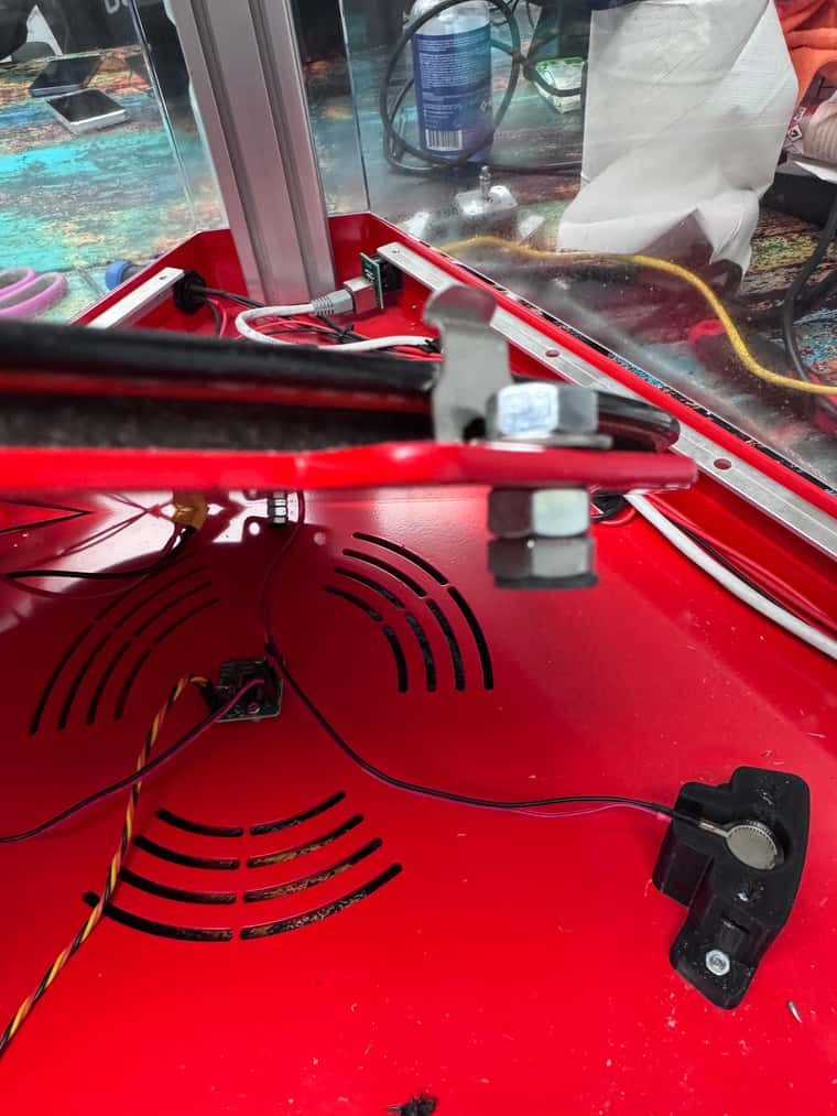
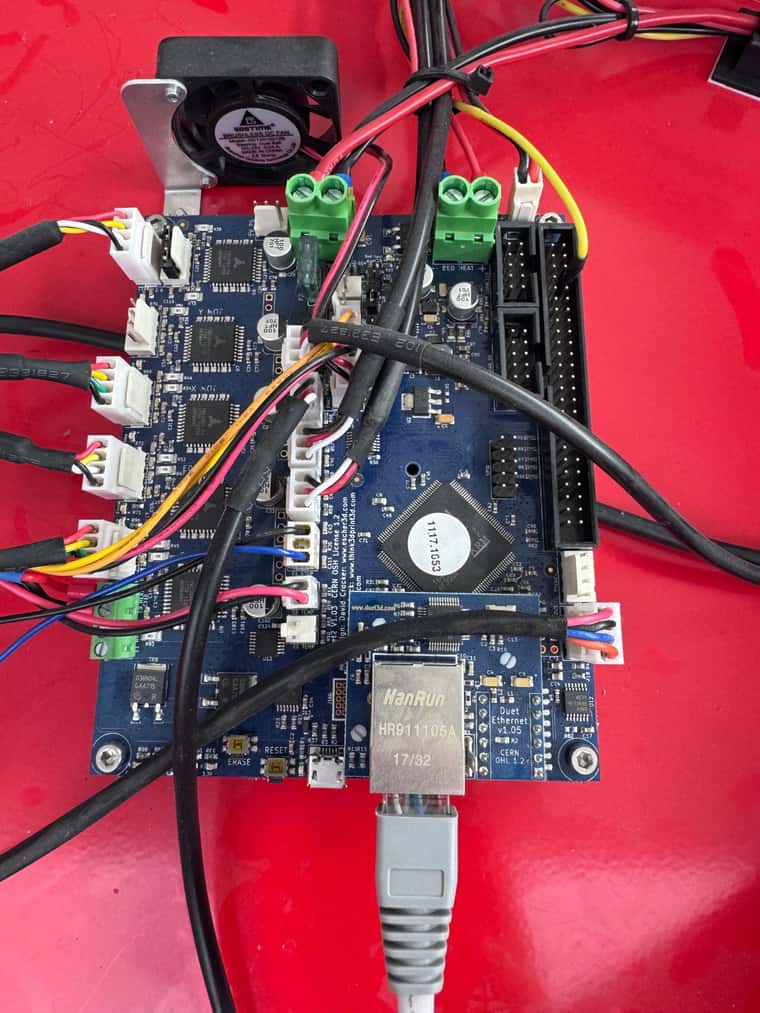
I am not sure how to check if this is working properly and what I would need to do to fix it. I have attached some pictures of the printer and the bed.
Is there anything I can do with the software to reduce this inconsistency? I am really stuck and not sure what to do.
Any help would be much appreciated. Thanks
; Configuration file for RepRapFirmware on Duet 2 Ethernet
; executed by the firmware on start-up
;
; generated by RepRapFirmware Configuration Tool v3.5.4 on Fri Aug 16 2024 12:20:56 GMT+0100 (British Summer Time)

; General

G90                        ; absolute positioning
M83 ; relative extruder moves
M550 P"T1250" ; set hostname

; Accessories
M575 P1 S0 B57600 ; configure PanelDue support

; Network
M552 P0.0.0.0 S1 ; configure Ethernet adapter
M586 P0 S1 ; configure HTTP

; Smart Drivers
M569 P0 S1 D2 ; driver 0 goes forwards (extruder 0)
M569 P2 S0 D2 ; driver 2 goes backwards (X axis)
M569 P3 S0 D2 ; driver 3 goes backwards (Z axis)
M569 P4 S0 D2 ; driver 4 goes backwards (Y axis)

; Motor Idle Current Reduction
M906 I40 ; set motor current idle factor
M84 S30 ; set motor current idle timeout

; Axes
M584 X2 Y4 Z3 ; set axis mapping
M350 X16 Y16 Z16 I1 ; configure microstepping with interpolation
M906 X1700 Y1700 Z1700 ; set axis driver currents
M92 X160 Y160 Z160 ; configure steps per mm
M566 X30000 Y30000 Z30000 ; set maximum instantaneous speed changes (mm/min)
M203 X36000 Y36000 Z36000 ; set maximum speeds (mm/min)
M201 X4000 Y4000 Z4000 ; set accelerations (mm/s^2)

; Extruders
M584 E0 ; set extruder mapping
M350 E16 I1 ; configure microstepping with interpolation
M906 E1100 ; set extruder driver currents
M92 E357.14286 ; configure steps per mm
M566 E18000 ; set maximum instantaneous speed changes (mm/min)
M203 E18000 ; set maximum speeds (mm/min)
M201 E4000 ; set accelerations (mm/s^2)

; Kinematics
M665 L457.600 R267.126 B175 H679.885 ; set delta radius, diagonal rod length, printable radius and homed height
M208 Z0 S1 ; set minimum Z
M666 X0 Y-0 Z-0 A0 B0 ; endstop adjustments and XY tilt, can be determined using auto calibration as well

; Probes
M558 K0 P5 C"e0stop" H5 F120 T18000 R0.2 A3 ; configure digital probe via slot #0
M558 H5 ;*** Remove this line after delta calibration has been done and new delta parameters have been saved
G31 P500 X0 Y0 Z-0.555  ; set Z probe trigger value, offset and trigger height

;Bed Mesh
M557 R150 S50 ;bed probe grid

; Endstops
M574 X2 P"xstop" S1 ; configure X axis endstop
M574 Y2 P"ystop" S1 ; configure Y axis endstop
M574 Z2 P"zstop" S1 ; configure Z axis endstop

; Sensors
M308 S0 P"bedtemp" Y"thermistor" A"Heated Bed" T100000 B4725 C7.06e-8 ; configure sensor #0
M308 S1 P"e0temp" Y"thermistor" A"Nozzle" T100000 B4267 C7.06e-8 ; configure sensor #1

; Heaters
M950 H0 C"bedheat" T0 ; create heater #0 (bed)
M143 H0 P0 T0 C0 S140 A0 ; configure heater monitor #0 for heater #0
M307 H0 R0.337 K0.353:0.000 D2.69 E1.35 S1.00 B0 ; configure model of heater #0
M950 H1 C"e0heat" T1 ; create heater #1 (Nozzle)
M143 H1 P0 T1 C0 S285 A0 ; configure heater monitor #0 for heater #1
M307 H1 R2.43 D5.5 E1.35 K0.56 B0 ; configure model of heater #1

; Heated beds
M140 P0 H0 ; configure heated bed #0

; Fans
M950 F0 C"fan0" ; create fan #0
M106 P0 S0 L0 X1 B0.1 ; configure fan #0
M950 F1 C"fan1" ; create fan #1
M106 P1 S0 B0.1 H1 T50 ; configure fan #1
M950 F2 C"fan2" ; create fan #2
M106 P2 S1 L0 X0.6 B0.1 ; configure fan #2

; Tools
M563 P0 D0 H1 F0 ; create tool #0
M568 P0 R0 S0 ; set initial tool #0 active and standby temperatures to 0C
; bed.g ; called to perform automatic delta calibration ; ; generated by RepRapFirmware Configuration Tool v3.5.4 on Fri Aug 16 2024 12:20:56 GMT+0100 (British Summer Time) G28 ; home the towers first ; Probe the bed at 12 peripheral and 6 halfway points, and perform 6-factor auto compensation ; Before running this, you should have set up your Z-probe trigger height to suit your build, in the G31 command in config.g. G30 P0 X0 Y84.9 H0 Z-99999 G30 P1 X42.45 Y73.53 H0 Z-99999 G30 P2 X73.53 Y42.45 H0 Z-99999 G30 P3 X84.9 Y0 H0 Z-99999 G30 P4 X73.53 Y-42.45 H0 Z-99999 G30 P5 X42.45 Y-73.53 H0 Z-99999 G30 P6 X0 Y-84.9 H0 Z-99999 G30 P7 X-42.45 Y-73.53 H0 Z-99999 G30 P8 X-73.53 Y-42.45 H0 Z-99999 G30 P9 X-84.9 Y0 H0 Z-99999 G30 P10 X-73.53 Y42.45 H0 Z-99999 G30 P11 X-42.45 Y73.53 H0 Z-99999 G30 P12 X0 Y42.4 H0 Z-99999 G30 P13 X36.72 Y21.2 H0 Z-99999 G30 P14 X36.72 Y-21.2 H0 Z-99999 G30 P15 X0 Y-42.4 H0 Z-99999 G30 P16 X-36.72 Y-21.2 H0 Z-99999 G30 P17 X-36.72 Y21.2 H0 Z-99999 G30 P18 X0 Y0 H0 Z-99999 S6 ; Use S-1 for measurements only, without calculations. Use S4 for endstop heights and Z-height only. Use S6 for full 6 factors ; If your Z probe has significantly different trigger heights depending on XY position, adjust the H parameters in the G30 commands accordingly. The value of each H parameter should be (trigger height at that XY position) - (trigger height at centre of bed) -
-
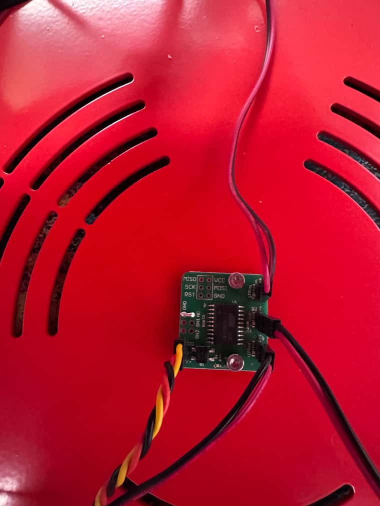
@JJJJ I'm pretty sure those are piezo sensors under the three mounting points of the bed. The small board in the middle is an amplifier, that generates a signal that the Duet understands from the input of the Piezo sensors. These register the contact of the nozzle on the bed. To do that, the nozzle has to hit with sufficient speed to register. Currently, your probe is set as:
; Probes
M558 K0 P5 C"e0stop" H5 F120 T18000 R0.2 A3 ; configure digital probe via slot #0
For the meaning, see https://docs.duet3d.com/User_manual/Reference/Gcodes#m558-set-z-probe-type
This old thread has some good info on setting up piezo sensors, but be careful, as it is written for the old version of RepRapFirmware, so the commands have changed, and only the last couple of posts in the thread are for RRF 3.x: https://forum.duet3d.com/topic/2671/precision-piezo-z-probes-guide-for-duet-users-reference
In particular, I think this is useful:
Probing speed F parameter (in mm/min). A value from 300-420 is recommended. Slower can give more accuracy but too slow may not trigger, as the probe generates a signal on a change (compression or flexing in the piezo disc.
and
Please note as of RRF version 1.20 (and later) you can use M558 P8 instead (other parameters are the same) which is a digital probe but without filtering or smoothing of the signal. This increases accuracy, as it takes less time to react to a trigger.
So, generally, I think your probing speed is too slow, at F120, and switching to P8 should make a faster response. The last couple of posts in the thread have a very high probe speed of F2400 and F3000. I don't know if the probe type can be switched to analogue mode (P1), it depends on the output of the amplifier board, and you would need to connect it to the Probe input, not an endstop. Note that things like belt tightness, loose joints between the axes and effector, loose hot end, and/or filament on the nozzle will also affect the readings.
So I think you're going to have to experiment with the settings, and test if the accuracy improves with changes. To test the accuracy when you change settings, have a look at this thread for a macro: https://forum.duet3d.com/topic/35200/probe-repeatability
Unfortunately, I can't find any example of the original Tractus3D configuration. If you have it, even if it was for the old version of RepRapFirmware, please post it. Tractus3D went bust, and it seems https://nexum3d.com/ has taken them over and sell some very Tractus3D-looking printers, so it may be worth getting in touch with them if you want the original
Ian
Bed-slinger - Mini5+ WiFi/1LC | RRP Fisher v1 - D2 WiFi | Polargraph - D2 WiFi | TronXY X5S - 6HC/Roto | CNC router - 6HC | Tractus3D T1250 - D2 Eth
-
@droftarts Thank you for your reply, that's very helpful I will try changing the speed then.
This is the printer they have at work and when I joined a few other people had already tried to get it working with no luck. When I went to update it I forgot to save the original config, it was on version 1. something. But it wasn't really working then anyway, so my plan was to start again so I did the config from scratch.
I have also struggled to find any information about the printer, so that explains why then.
I've managed to get some prints from it now I rewired the hot end and added a new extruder but it's just the first layer and z offset causing issues now.
I will try the things you have said, thanks again for your help.