BIQU Microprobe how do I set it up?
-
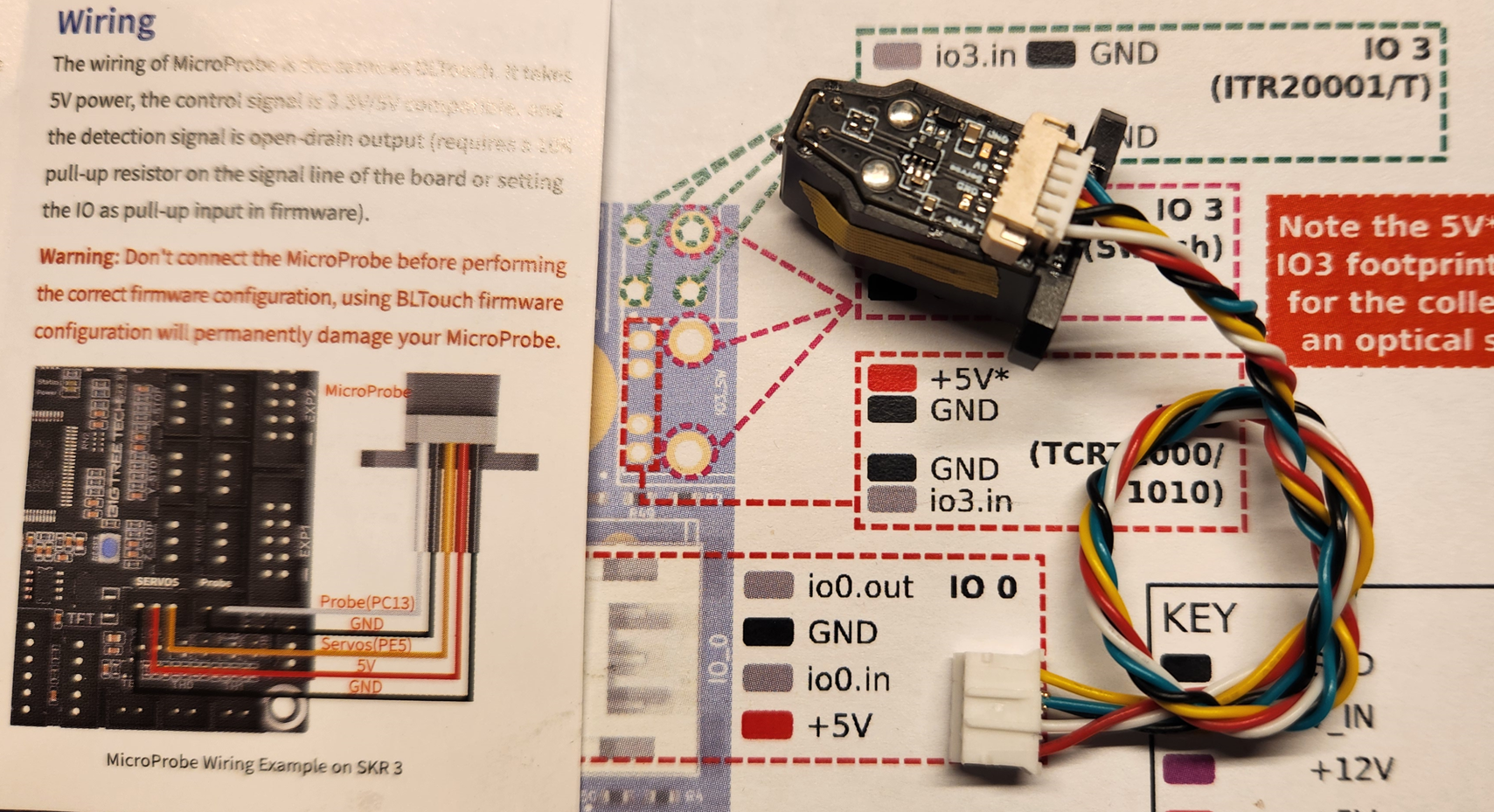
I am having trouble conneting a BIQU Microprobe, v. 2
It claims to be compatible with BL-Touch wiring. I have fully working BL-Touch connected to a Duet Toolboard.
The instructions that comes with the BIQU Microprobe warns that not having correctly configured software may damage the probe.
Checking the instructions on BIQUs site I understand it as for Duet board nothing needs to be changed.
However when I connect the BIQU probe I get an error message stating that the toolboard stopped reporting status and the hotend fan stops. If I disconnect it the fan starts again. I am suspecting something gets shorted.
Now I have probe number 3, and I do NOT want to fry something.
Fw version 3.5.3 on both Mini 5 board and toolboard.
Condig.g below.
How do I configure/wire this?
; Configuration file for Duet 3 Mini 5+ (firmware version 3) ; executed by the firmware on start-up ; ; generated by RepRapFirmware Configuration Tool v3.2.3 on Mon Jul 05 2021 16:50:46 GMT+0200 (Central European Summer Time) ; General preferences G90 ; send absolute coordinates... M83 ; ...but relative extruder moves M669 K1 ; select CoreXY mode ; Network M552 S1 ; enable network M586 P0 S1 T0 ; enable HTTP M586 P1 S1 ; disable FTP M586 P2 S0 ; disable Telnet M586 C"*" M550 P"DUET" ; set printer name M929 P"_eventlog.txt" S1 ;start logging ; Drives M569 P0.2 S0 D3 V10 ; physical drive 0.2 ZL goes forwards M569 P0.4 S0 D3 V10 ; physical drive 0.4 ZM goes forwards M569 P0.3 S0 D3 V10 ; physical drive 0.3 ZR goes forwards M569 P121.0 S1 D2 ; physical drive 121.0 E goes forwards M569 P0.0 S1 D2 ; physical drive 0.0 Y goes backwards M569 P0.1 S1 D2 ; physical drive 0.1 X goes backwards M584 X0.0 Y0.1 Z0.2:0.4:0.3 E121.0 ; set drive mapping M350 X16 Y16 Z16 E16 I1 ; configure microstepping with interpolation M92 X80.00 Y80.0 Z800.00 E716.256 ; set steps per mm ; Speed and Acceleration ;M98 P"0:/sys/setspeeds.g" M566 X600.00 Y600.00 Z100.00 E120.00 P1 ; set maximum instantaneous speed changes (mm/min) and jerk policy M203 X30000.00 Y30000.00 Z1200.00 E6000.00 ; set maximum speeds (mm/min) M201 X5000.00 Y5000.00 Z120.00 E3600.00 ; set accelerations (mm/s^2) M204 P8000 T8000 ; Driver Current M906 X1700 Y1700 Z1000 E800 I50 ; set motor currents (mA) and motor idle factor in percentage M917 X70 Y70 Z70 E70 ; stand still current factor in percentage M84 S30 ; Set idle timeout ; Axis Limits M208 X0 Y0 Z0 S1 ; set axis minima M208 X298 Y294 Z300 S0 ; set axis maxima ; Endstops M574 X1 S1 P"!121.io3.in" ; configure active-high endstop for low end on X via pin 121.io3.in M574 Y2 S1 P"!io6.in" ; configure active-high endstop for high end on Y via pin io6.in ; Z-Probe M950 S0 C"^121.io0.out" ; create servo pin 0 for BLTouch M558 P9 C"^121.io0.in" H3 F300:100:100 T18000 A6 S0.04 ; set Z probe type to bltouch and the dive height + speeds ;################################### G31 P500 X-26.6 Y-18.6 Z1.99 ; BLTouch set Z probe trigger value, offset and trigger height. ;################################### M671 X-6.6:147.9:302.4 Y-1:308:-1 P10 S3.0 M557 X5:263 Y5:275 P7 ; define mesh grid ; Heaters ;Bed M308 S0 P"temp0" Y"thermistor" T100000 B4138 ; configure sensor 0 as thermistor on pin temp0 M950 H0 C"out1" T0 ; create bed heater output on out0 and map it to sensor 0 M307 H0 B0 S1.00 ; disable bang-bang mode for the bed heater and set PWM limit M140 H0 ; map heated bed to heater 0 M143 H0 S120 ; set temperature limit for heater 0 to 120C M307 H0 R0.489 K0.256:0.000 D3.89 E1.35 S1.00 B0 ;Hotend M308 S1 P"121.temp0" Y"pt1000" ; configure sensor 1 as pt1000 on pin 121.temp0 M950 H1 C"121.out0" T1 ; create nozzle heater output on 121.out0 and map it to sensor 1 M307 H1 B0 S1.00 ; disable bang-bang mode for heater and set PWM limit M143 H1 S300; set temperature limit for heater 1 to 300C M307 H1 R3.509 K0.442:0.000 D7.05 E1.35 S1.00 B0 V23.8 M308 S2 P"mcutemp" Y"mcutemp" A"Duet Board" ; Configure MCU sensor M308 S11 Y"drivers" A"Duet stepper drivers" ; Fans M950 F0 C"121.out2" Q500 ; create fan 0 on pin 121.out2 and set its frequency M106 P0 S255 C"Hotend" S0 H1 L1.0 X1.0 T45 ; set fan 0 value. Thermostatic control is turned on M950 F1 C"121.out1" Q500 ; create fan 1 on pin 121.out1 and set its frequency M106 P1 0 H-1 L0.4 X1.0 C"Part Cooling" ; Buttons ;M950 J1 C"io1.in" ; TOP Button 1 (Top) ;M581 P1 T2 ; trigger2.g ;M950 J2 C"io2.in" ; Button 2 ;M581 P2 T3 ; trigger3.g ;M950 J3 C"io3.in" ; Button 3 ;M581 P3 T4 ; trigger4.g ;M950 J4 C"io4.in" ; Button 4 ;M581 P4 T5 ; trigger5.g ;M950 J5 C"io5.in" ; Button 5 (Bottom) ;M581 P5 T6 ; trigger6.g M950 J5 C"io5.in" ; inverted, in pin not grounded causes trigger to execute M581 P5 S1 T1 R1; T1 => trigger PAUSE M25, R1 only when printing ; Accelerometer M955 P121.0 I10 R12 ; Tools M563 P0 D0 H1 F1 ; define tool 0 G10 P0 X0 Y0 Z0 ; set tool 0 axis offsets G10 P0 R0 S0 ; set initial tool 0 active and standby temperatures to 0C M575 P1 S1 B57600 ; PanelDue M593 P"zvddd" F48.7 ; Input Shaper M572 D0 S0.025 ; Pressure Advance ;G29 S1 ; Load mesh bed compensation M376 H10 ; Taper out mesh bed compensation ;LED M950 E0 C"led" T2 Q3000000 ; configure LED light to Neopixel RGBW ; Miscellaneous M501 ; load saved parameters from non-volatile memory T0 ; select first tool M150 U255 P255 S120 F0 ; LED Green glow -
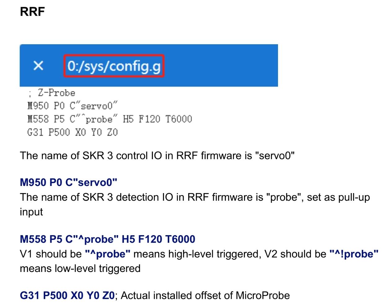
BIQU instructions
-
@fotomas https://teamgloomy.github.io/fly_e3_pro_v3_bltouch_3_5.html#configg-changes-1
See here for microprobe config changes for RRF. It doesn't use a servo so you don't use an S in M950. You also need to change your deploy and retract macros.
Don't forget to invert the probe for the V2 as well -
I made the following changes to config.g (BLTouch config commented out below)
; Z-Probe
M558 P9 C"^!121.io0.in" H3 F300:100:100 T18000 A6 S0.04 ; set Z probe type and the dive height + speeds
M950 P0 C"^121.io0.out"                                 ; create pin 0 for BIQU Microprobe

;M950 S0 C"^121.io0.out"                                ; create servo pin 0 for BLTouch
;M558 P9 C"^121.io0.in" H3 F300:100:100 T18000 A6 S0.04 ; set Z probe type to bltouch and the dive height + speeds

;###################################
G31 P500 X-26.6 Y-18.6  Z1.99                           ;Set Z probe trigger value, offset and trigger height.
I crimped a new cable. Joined the two ground wires from the probe to the one GND on the toolboard.
As soon as I connect it the DUET halts. Disconnecting it, the DUET somewhat recovers. Restarting the DUET it is all fine again.Connected BLTouch with new cable and reverted the config, it all works as before/expected.
Can the probe have been damaged by the S0 in the M950 command?
I have several probes (BIQU Sale) to try with but only one compleatly ontouched/tested that I am saving until this has been sorted.
-
@fotomas I can't see anything wrong with your wiring.
I'm not aware of it being possible to damage when programmed as a probe. We do have a few users who haven't been able to get one working recently though. I've only ever tested a v1 microprobe. I don't have a V2.