Posted this part in the RatRig discord server. But it has a limited Duet3D fan base. So posting here too.
https://www.printables.com/model/967347-eva3-back-plate-tension-less-duet3d-tool-board
Posted this part in the RatRig discord server. But it has a limited Duet3D fan base. So posting here too.
https://www.printables.com/model/967347-eva3-back-plate-tension-less-duet3d-tool-board
@kipk
I have reserved one at
https://www.dold-mechatronik.de/
They expect it to be in stock next week.
@jay_s_uk Great tip, thank you. i will look into that.
Both that wiki and the GCode Dictionary explains thing with the term "Z leadscrews" which is correct in some hardware configurations. But it fooled me, maybe reading too quickly and not fully comprehending tings.
I propose a change to the use of "pivot point" or equivalent to make things a bit less likely to misunderstand.
@droftarts I have limited knowledge in this area, but would it be possible by using an arduino converting it to an analog signal and use that signal as a temp sensor on the Duet?
One would then get a curve plotted in the web interface and a neat way to control an extraction fan with "temp" levels in the M106 command.
Final settings (for future use by anyone interested):
config.g
-----------------------------------------
; Drives
M584 X0:3 Y1:4 Z2 U3 V4 P3; Three axis visible

; Tools
M563 P0 D0

; Drive direction
M569 P0 S1                       ; Drive 0 goes forwards
M569 P1 S1                       ; Drive 1 goes forwards
M569 P2 S1                       ; Drive 2 goes forwards
M569 P3 S1
M569 P4 S1

; Steps and Speed
M92 X80.00 Y80.00 U80.00 V80.00 Z4000.00 ; Set steps per mm
M566 X900.00 Y900.00 U900.00 V900.00 Z12.00; Set maximum instantaneous speed changes (mm/min)
M203 X6000.00 Y6000.00 Z180.00 U6000.00 V6000.00; Set maximum speeds (mm/min)
M201 X500.00 Y500.00 Z20.00 U500.00 V500.00; Set accelerations (mm/s^2)
M906 X800.00 Y800.00 Z800.00 U800.00 V800.00 I30; motor currents (mA) and motor idle factor
M84 S30  ; Set idle timeout

; Axis Limits
M208 X0 Y0 Z0 U0 V0 S1                 ; Set axis minima
M208 X600 Y400 Z100 U600 V600 S0           ; Set axis maxima

; Endstops
M574 X1 Y1 U1 V1 S0               ; Set active low and disabled endstops

homex.g
----------------------------------------
M584 X0 U3 P5; split steppers, 5 axis visible
G91 ; relative moves
G1 X-650 U-650  F450 S1 ; fast homing X and U in parallell
;G92 X0 U0 ; Make adjustments to square axis here
M584 X0:3 P3; join steppers, 3 axis visible
G90dsmudger
I would say these are major steps
Original connectors can be forced into the Duet board, but I ended up making adapters both for the steppers and the hot end. Pictures below show before the adapters during "proof of concept phase". On the hotend it self I made a new board using experimental circuit board and matching connectors. There was too much interference in the ribbon cable for the signal from the IR board so I added an ethernet (twisted pair) cable for that.
If there are any questions I would be happy to help.


Never used them, can not reach them with my fingers when mounted on my printer.
I got no voltage at those points. Not with or without an object within range.
I made several tests to be sure sonce i did net get any readots at all.
As a last test I was thinking of trying to shine some IR light on the sensor using the old ormerod sensor or a tv remote.
Settimg this up it started working again!!?? I did not get to the point using another IR source.
I have disconnected it several times and kept working then it stopped working again.
I have upgraded my duet-controlled Cetud3d with a Hemera extruder. I have been testing how fast it can print and still have not reached its limits.
Peak speed in the PLA print below is about 250 mm/s , reported by DWC.
This is unnecessary and so much FUN 
https://youtu.be/gCN8IdGvwas
@fotomas
Did a test, first layer transparent PLA layed down in a concentric pattern. On top of that black and red PLA and lastlt a black layer. All layers printed with a .4 mm nozzle and layerheight .4 mm. The coaster has a diameter of 80 mm.
There some moiré effects so there are things to improve. But as a first test I think it worked out fine.
(The text translates to "transmission interruption")


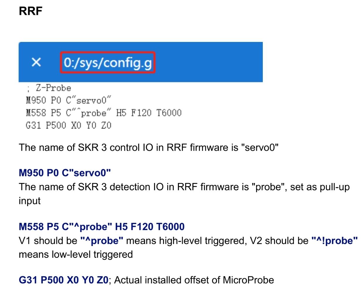
I made the following changes to config.g (BLTouch config commented out below)
; Z-Probe
M558 P9 C"^!121.io0.in" H3 F300:100:100 T18000 A6 S0.04 ; set Z probe type and the dive height + speeds
M950 P0 C"^121.io0.out"                                 ; create pin 0 for BIQU Microprobe

;M950 S0 C"^121.io0.out"                                ; create servo pin 0 for BLTouch
;M558 P9 C"^121.io0.in" H3 F300:100:100 T18000 A6 S0.04 ; set Z probe type to bltouch and the dive height + speeds

;###################################
G31 P500 X-26.6 Y-18.6  Z1.99                           ;Set Z probe trigger value, offset and trigger height.
I crimped a new cable. Joined the two ground wires from the probe to the one GND on the toolboard.
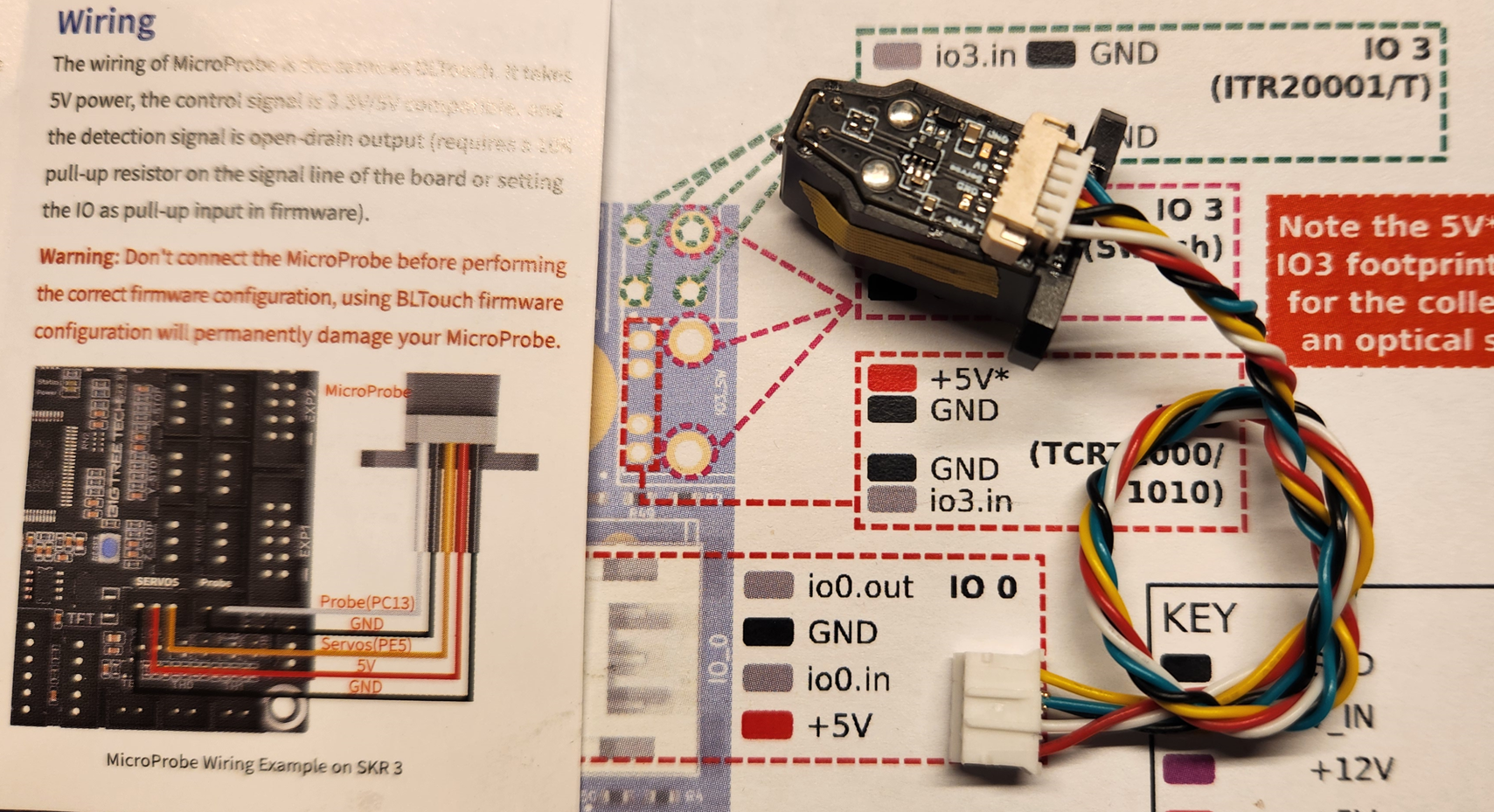
As soon as I connect it the DUET halts. Disconnecting it, the DUET somewhat recovers. Restarting the DUET it is all fine again.
Connected BLTouch with new cable and reverted the config, it all works as before/expected.
Can the probe have been damaged by the S0 in the M950 command?
I have several probes (BIQU Sale) to try with but only one compleatly ontouched/tested that I am saving until this has been sorted.
I am having trouble conneting a BIQU Microprobe, v. 2
It claims to be compatible with BL-Touch wiring. I have fully working BL-Touch connected to a Duet Toolboard.
The instructions that comes with the BIQU Microprobe warns that not having correctly configured software may damage the probe.
Checking the instructions on BIQUs site I understand it as for Duet board nothing needs to be changed.
However when I connect the BIQU probe I get an error message stating that the toolboard stopped reporting status and the hotend fan stops. If I disconnect it the fan starts again. I am suspecting something gets shorted.
Now I have probe number 3, and I do NOT want to fry something.
Fw version 3.5.3 on both Mini 5 board and toolboard.
Condig.g below.
How do I configure/wire this?
; Configuration file for Duet 3 Mini 5+ (firmware version 3)
; executed by the firmware on start-up
;
; generated by RepRapFirmware Configuration Tool v3.2.3 on Mon Jul 05 2021 16:50:46 GMT+0200 (Central European Summer Time)

; General preferences
G90                                                     ; send absolute coordinates...
M83                                                     ; ...but relative extruder moves
M669 K1                                                 ; select CoreXY mode

; Network
M552 S1                                                 ; enable network
M586 P0 S1 T0                                              ; enable HTTP
M586 P1 S1                                              ; disable FTP
M586 P2 S0                                              ; disable Telnet
M586 C"*"
M550 P"DUET"                                 		; set printer name

M929 P"_eventlog.txt" S1								;start logging

; Drives
M569 P0.2 S0 D3 V10                                   ; physical drive 0.2 ZL goes forwards
M569 P0.4 S0 D3 V10                                   ; physical drive 0.4 ZM goes forwards
M569 P0.3 S0 D3 V10                                   ; physical drive 0.3 ZR goes forwards

M569 P121.0 S1 D2                                     ; physical drive 121.0 E goes forwards
M569 P0.0 S1 D2                                       ; physical drive 0.0 Y goes backwards
M569 P0.1 S1 D2                                       ; physical drive 0.1 X goes backwards

M584 X0.0 Y0.1 Z0.2:0.4:0.3 E121.0                    ; set drive mapping

M350 X16 Y16 Z16 E16 I1                               ; configure microstepping with interpolation
M92 X80.00 Y80.0 Z800.00 E716.256                        ; set steps per mm

; Speed and Acceleration
;M98 P"0:/sys/setspeeds.g"
M566 X600.00 Y600.00 Z100.00 E120.00 P1      ; set maximum instantaneous speed changes (mm/min) and jerk policy
M203 X30000.00 Y30000.00 Z1200.00 E6000.00 ; set maximum speeds (mm/min)
M201 X5000.00 Y5000.00 Z120.00 E3600.00    ; set accelerations (mm/s^2)
M204 P8000 T8000

; Driver Current
M906 X1700 Y1700 Z1000 E800 I50                       ; set motor currents (mA) and motor idle factor in percentage
M917 X70 Y70 Z70 E70                                  ; stand still current factor in percentage
M84 S30                                               ; Set idle timeout

; Axis Limits
M208 X0 Y0 Z0 S1                                      ; set axis minima
M208 X298 Y294 Z300 S0                                ; set axis maxima

; Endstops
M574 X1 S1 P"!121.io3.in"                              ; configure active-high endstop for low end on X via pin 121.io3.in
M574 Y2 S1 P"!io6.in"                                  ; configure active-high endstop for high end on Y via pin io6.in

; Z-Probe
M950 S0 C"^121.io0.out"                          ; create servo pin 0 for BLTouch
M558 P9 C"^121.io0.in" H3 F300:100:100 T18000 A6 S0.04            ; set Z probe type to bltouch and the dive height + speeds


;###################################
G31 P500 X-26.6 Y-18.6  Z1.99 ; BLTouch set Z probe trigger value, offset and trigger height.
;###################################

M671 X-6.6:147.9:302.4 Y-1:308:-1 P10 S3.0
M557 X5:263 Y5:275 P7                               ; define mesh grid

; Heaters
;Bed
M308 S0 P"temp0" Y"thermistor" T100000 B4138				; configure sensor 0 as thermistor on pin temp0
M950 H0 C"out1" T0                                      ; create bed heater output on out0 and map it to sensor 0
M307 H0 B0 S1.00                                        ; disable bang-bang mode for the bed heater and set PWM limit
M140 H0                                                 ; map heated bed to heater 0
M143 H0 S120                                            ; set temperature limit for heater 0 to 120C
M307 H0 R0.489 K0.256:0.000 D3.89 E1.35 S1.00 B0

;Hotend
M308 S1 P"121.temp0" Y"pt1000"							; configure sensor 1 as pt1000 on pin 121.temp0
M950 H1 C"121.out0" T1                                  ; create nozzle heater output on 121.out0 and map it to sensor 1
M307 H1 B0 S1.00                                        ; disable bang-bang mode for heater  and set PWM limit
M143 H1 S300; set temperature limit for heater 1 to 300C
M307 H1 R3.509 K0.442:0.000 D7.05 E1.35 S1.00 B0 V23.8


M308 S2 P"mcutemp" Y"mcutemp" A"Duet Board"           ; Configure MCU sensor
M308 S11 Y"drivers" A"Duet stepper drivers"

; Fans
M950 F0 C"121.out2" Q500                                ; create fan 0 on pin 121.out2 and set its frequency
M106 P0 S255 C"Hotend" S0 H1 L1.0 X1.0 T45              ; set fan 0 value. Thermostatic control is turned on
M950 F1 C"121.out1" Q500                                ; create fan 1 on pin 121.out1 and set its frequency
M106 P1 0 H-1 L0.4 X1.0 C"Part Cooling"

; Buttons
 ;M950 J1 C"io1.in" ; TOP Button 1 (Top)
 ;M581 P1 T2 ; trigger2.g
 ;M950 J2 C"io2.in" ; Button 2
 ;M581 P2 T3 ; trigger3.g
 ;M950 J3 C"io3.in" ; Button 3
 ;M581 P3 T4 ; trigger4.g
 ;M950 J4 C"io4.in" ; Button 4
 ;M581 P4 T5 ; trigger5.g
 ;M950 J5 C"io5.in" ; Button 5 (Bottom)
 ;M581 P5 T6 ; trigger6.g
 M950 J5 C"io5.in" ; inverted, in pin not grounded causes trigger to execute
M581 P5 S1 T1 R1; T1 => trigger PAUSE M25, R1 only when printing

; Accelerometer
M955 P121.0 I10 R12

; Tools
M563 P0 D0 H1 F1                                      ; define tool 0
G10 P0 X0 Y0 Z0                                       ; set tool 0 axis offsets
G10 P0 R0 S0                                          ; set initial tool 0 active and standby temperatures to 0C

M575 P1 S1 B57600									; PanelDue
M593 P"zvddd" F48.7									; Input Shaper
M572 D0 S0.025 										; Pressure Advance
;G29 S1												; Load mesh bed compensation
M376 H10 											; Taper out mesh bed compensation

;LED
M950 E0 C"led" T2 Q3000000							; configure LED light to Neopixel RGBW

; Miscellaneous
M501                                                ; load saved parameters from non-volatile memory
T0                                                  ; select first tool
M150 U255 P255 S120 F0								; LED Green glow
After finding and adressing several issues I belive it is working fine now.
I have:
Lowered the jerk value for Z to 15
Let the bed soak properly before do bed mesh (temp 80 )
Replaced lost screw, one of three holding the hotend to the heatsink. This was hidden by the silicon sock on my Phaetus Rapido hotend.
I think the jerk value was the thing but the other two brought a fair amount of inconcistency too.
So i will end this thread/question here. Thank you for all the help and a little extra to Phaedrux.
Reading about E3D's new PZ Probe https://e3d-online.com/products/pz-probe
I wonder if it would be possible to connect to Duet3D's Toolboard. The wireing instructions states that it should be connected to the PanelDue port.
Also, the stand-alone version of PZ Probe should/can it be connected between the hotend heatsink and toolhead. Looking at the Voron version, it seems to be "inside" the heatsink somehow.
@timschneider There is no M207 in config.g or print code.
I have done more testing.
So it does not seem to relate to babystepping. I started thinking in terms of loosing steps on Z-Axis, below is my motor settings, start and end GCode (if any Z-moves messes things up)
... I am running out of ideas here, does any one hava any ideas for some controlled approach to narrow down the possibilities?
speed settings
M566 X600.00 Y600.00 Z500.00 E120.00 P1      ; set maximum instantaneous speed changes (mm/min) and jerk policy
M203 X30000.00 Y30000.00 Z1200.00 E6000.00 ; set maximum speeds (mm/min)
M201 X20000.00 Y20000.00 Z300.00 E5000						; set accelerations (mm/s^2)
M204 P10000 T20000
Start of print code
M140 S80 ; set bed temp and continue
M109 S245 ; set nozzle temp and wait
M190 S80 ; set bed temp and wait

M150 R255 U255 B255 W255 P255 S120 F0 ; Print lights

G1 X100 Y4 Z5 F5000
M73 P1 R1
G1 Z0.6
M73 P2 R1
G1 X200 Y4 E30 F1500
End of print code
M106 S0
M400 G91; relative positioning
G1 H2 Z25 F12000 ; lift Z relative to current position
G90 ; absolute positioning
G1 Y270 X10 F5000; move head back
M150 U255 P255 S120 F0 ; Print done lights, green
M0
I start my printer with bed.g G32 (code borrowed and tweaked) from someone at this forum:
M290 R0 S0      ; clear baby stepping
M561            ; clear any bed transform
M400            ; finish all moves, clear the buffer

if !move.axes[0].homed || !move.axes[1].homed || !move.axes[2].homed
	G28             ; home all

M201 X1000 Y1000  ; reduce acceleration

; calibrate bed
while true
  if iterations = 5
    abort "Auto calibration repeated attempts ended, final deviation", move.calibration.final.deviation ^ "mm"
  G30 P0 X5 Y10 Z-99999 ; probe near a leadscrew
  if result != 0
    continue
  G30 P1 X150 Y275 Z-99999 ; probe near a leadscrew
  if result != 0
    continue
  G30 P2 X270 Y10 Z-99999 S3 ; probe near a leadscrew and calibrate 3 motors
  if result != 0
    continue
  if move.calibration.initial.deviation <= 0.05
    break
  echo "Repeating calibration because deviation is too high (" ^ move.calibration.initial.deviation ^ "mm)"
; end loop
echo "Auto calibration successful, deviation", move.calibration.final.deviation ^ "mm"
G0 X150 Y150 F12000

G28 Z                     ; rehome Z as the absolute height of the z plane may have shifted
G29 S1                    ; load saved mesh
M98 P"0:/sys/setspeeds.g" ; set speed and acceleration
@oliof No the value on PanelDue and DWC remains at 0.1
@gloomyandy That is a good question. I will test that ASAP
@oliof I set babystepping via PanelDue, see OP.
After som testeing I have drawn the conclusion that babystep settings accumulates between each print.
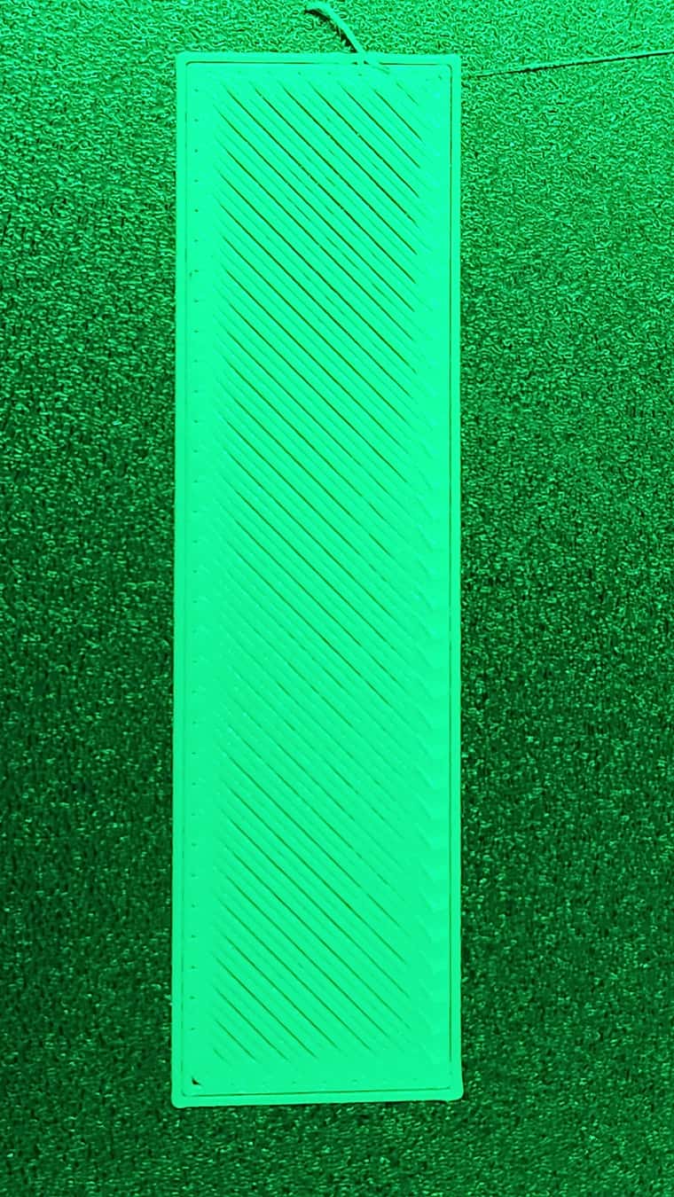
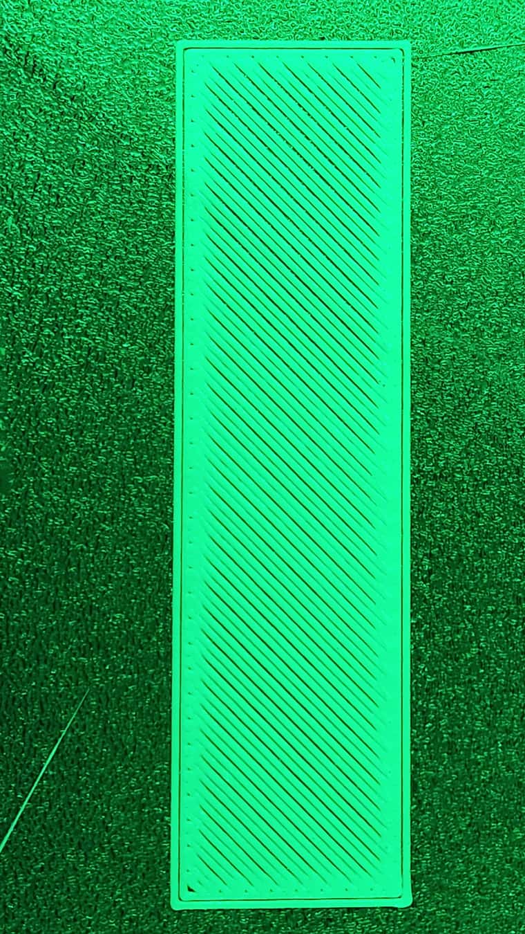
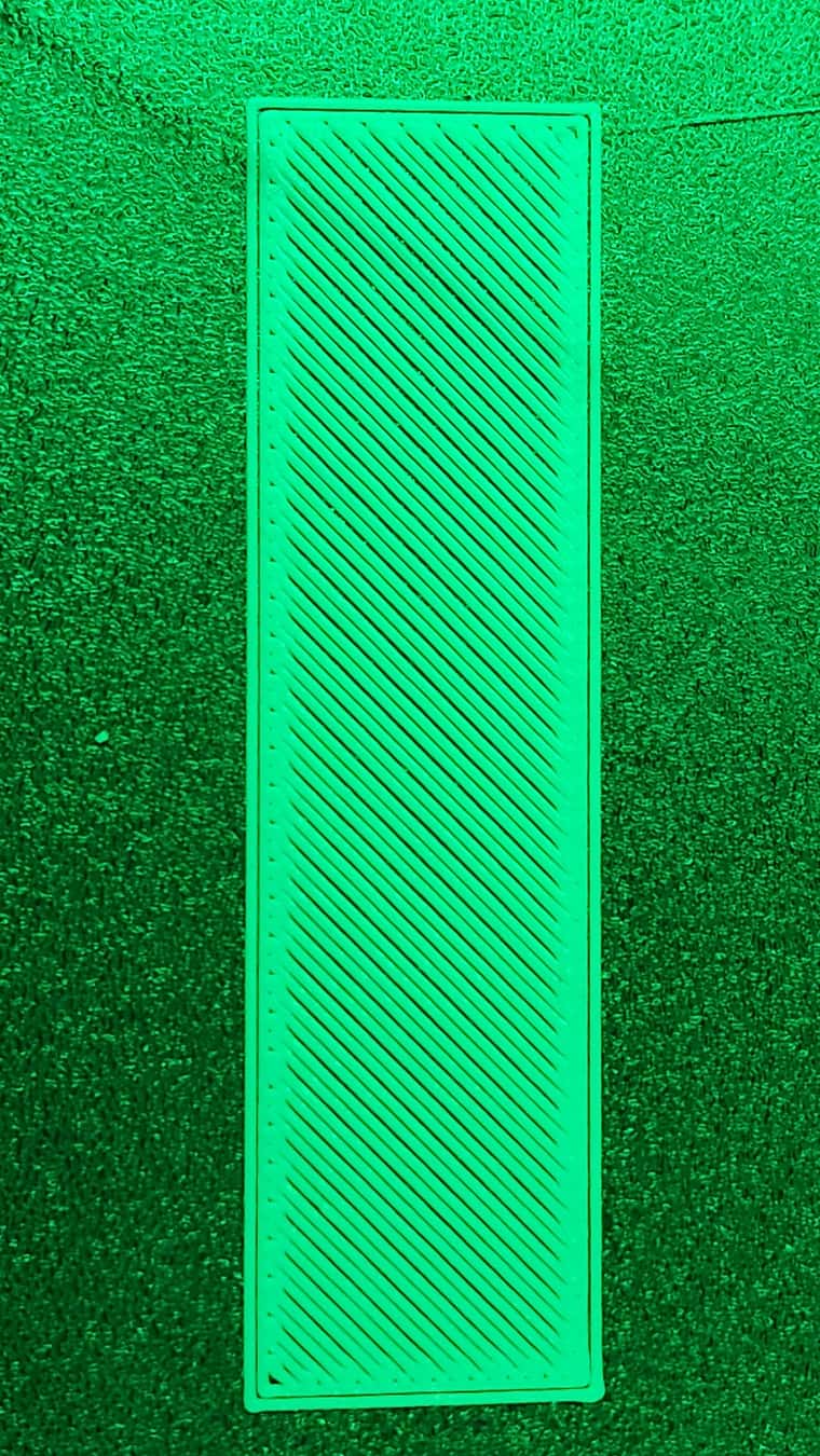
These are three consecutive prints (sorry for the green light, LED strip signaling finished print).
Baystep is set to 0.1 mm "higher" and as can be seen it prints higher and higher for each print.
Babystep is set by PanelDue FW 3.5.0
RepRapFirmware for Duet 3 Mini 5+ version 3.5.2 (2024-06-11 17:14:16) running on Duet 3 Mini5plus WiFi (standalone mode)
config.g and g-code for the print attached, sliced with Orca Slicer.
What can be the cause of this?