Homeall.g fails when homing all axes
-
@developeralgo222
i can confirm that the issue seems to be either DWC or Duet3D Firmware because it seems to home the individual axes but you still get an error " Failed to home axes ". As i said above homeall behaves differently it only home all other axes but not X & YThis needs to be fixed. i need to configure the Accelerometer to collect Acceleration Data on X & Y for input shaping and fine tuning but i can't do that in input shaping plugin if it can't see status of the X & Y & Z as being homed.
-
To me it doesn't seem likely that the problem is in the firmware.
And, if you would be so kind, in the future please post files using the </> tag, rather than as a links.
With the </> tag the code appears right in your post and we all don't have to download files just to look at them.
Thanks.
Frederick
-
I saw another problem. you have two endstops defined in config.g for some axis but only one is supported so the second endstop command is the one that is being used. for example:
M574 Z1 S1 P"!1.io0.in"             ; configure active high endstop switch for low end on Z via pin 1.io0.in
M574 Z2 S1 P"!1.io1.in"             ; configure active high endstop switch for High end on Z via pin 1.io1.in
only the high end endstop is used.
Did you try mu modified hmex.g to see if it worked?
-
@T3P3Tony
Got major issues with endstop triggers and need your help guysi was just going through the endstops again . Here is what i have noticed.
Explanation:
(1) For X-axis i have 2 endstops (1 NEMA34 Stepper motor on the X-axis , one at 0(min) and other at 340 (max) ) but both are connected together to act as 1 single endstop. So that if the machine touches any of them it will trigger for X-axis ( 2 physical endstops acting as 1 endstop )
(2) For Y-Axis i have 4 endstops ( 1 NEMA34 Stepper motor on the Y-axis with 2 Linear rails , each Linear rail has one at 0(min) and other at 447 (max) but all 4 endstops are connected together to act as 1 single endstop. So that if the machine touches any of them it will trigger for Y-axis ( 4 physical endstops acting as 1 endstop)
(3) For Z, U, V because they are shared Z-based CAM axes .i.e Z = ( Z1, Z2 ) , U = (Z3, Z4), V = ( Z5 , Z6 ) . Each of them has its own single endstop ( 6 endstops in total)
(4) For Rotational axes W, A, B, C, D, k -- all have their own single endstop ( 6 endstops in total )
Observed trigger testing Results when covering the endstop optical lights to trigger the endstops:
NOTE: For all axes , i observed that if i moved the machine to where it should trigger the axis endstop. it shows that its triggered on the dashboard. but when i move the machine away from the endstop it does not show that its not triggered. is this normal ?
(1) For X , it only actually triggers when both 2 physical endstops are touched at the same time. This actions really opposite of what i would like , which if any of the 2 physical ends is touched it triggers
(2) For Y , it only actually triggers when all 4 physical endstops are touched at the same time. This actions really opposite of what i would like , which if any of the 4 physical ends is touched it triggers
(3) Z , U , V ( Z1, Z2, Z3, Z4, Z5, Z6 ) only Z2 , Z3, Z6 triggers Z , U , V respectively but not Z1, Z3, Z5
(4) W,A,B,C,D,k all trigger
-
@developeralgo222
NOTE: all endstop triggers seem to be acting in the Opposite wayi.e if triggered it shows OFF on Dashboard and if not triggered it shows ON (Green) on the Dashboard
According the documentation :
In DWC v3.5 and later, the endstop status is indicated in the Status panel. If the endstop is triggered, a green square will highlight the axis that is triggered. If there is no green square, it is not triggered.
in my case its exactly opposite
-
For X-axis i have 2 endstops, one at 0(min) and other at 340 (max) ) but both are connected together to act as 1 single endstop
That's a problem: Endstops are a means to determine a physical location for an axis. If you can "home" the axis to two opposite locations, having both endstops wired together (i.e. in parallel), you are lost. Best is to just keep one endstop per axis.
-
according to Duet3 Documentation :
RepRapFirmware only supports one endstop per motor per axis. If your axis only has one motor, you can only have one endstop . is this still the case ?
On X-axis & Y-axis
To try and remedy this: i am thinking of doing this
(1) For X-axis , only have 1 physical endstop at min or max
(2) For Y-axis, only have 2 physical endstops (connected in parallel) each per Y-axis rail both at min or max
NOTE: i have the 4-wire Panasonic Optical Endstops PM-U25-N ( NPN type) (Black, Blue, Brown, white ) connected to Duet3D 6XD & 3HC board IO ports as follows:
Panasonic pm-254565_e_cata.pdf
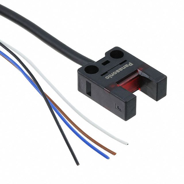
Black Wire ==> IOx.in
Blue Wire ==> GND
Brown Wire ==> 5V_EXTQuick Question: Normally what is the best location for an endstop for Duet3D 6XD boards is at Min or Max locations of the Axis ?
My triggers seem to be acting in reverse.
Trigger OFF means ON (Green on Dashboard) and Trigger ON means OFF for all axes
-
@developeralgo222 yes, that's still the case of 1 per axis.
It makes normal difference whether they are at min or max -
@developeralgo222 said in Homeall.g fails when homing all axes:
Trigger OFF means ON (Green on Dashboard) and Trigger ON means OFF for all axes
This is because the endstops are defined with the signal inverted, due to the "!", e.g.:
M574 X1 S1 P"!0.io1.in"see:
https://docs.duet3d.com/en/User_manual/Reference/Gcodes#m574-set-endstop-configurationTry
M574 X1 S1 P"0.io1.in"Its really worth following the documentation for setting up endstops:
https://docs.duet3d.com/en/User_manual/Connecting_hardware/Sensors_endstopsOnly have the endstop at one end of the axis.
Regarding this:
@developeralgo222 said in Homeall.g fails when homing all axes:
(2) For Y-axis, only have 2 physical endstops (connected in parallel) each per Y-axis rail both at min or max
However in your config.g you only have 1 motor on Y so you can only have 1 endstop:
M584 X0.0 Y0.1 Z1.0 U1.1 V1.2 W2.0 A2.1 B2.2 C3.0 D3.1 'k3.2 R0 S0 -
(1) For X-axis , only have 1 physical endstop at min or max
That's fine.
(2) For Y-axis, only have 2 physical endstops (connected in parallel) each per Y-axis rail both at min or max
Why? For each axis, you want to have one known position from where you then establish a coordinate system.
There are reasons to become confused:
- in case you have multiple steppers per axis (think of 3 motors for Z), you may want to level or tram the printbed or maybe the X plane (2 steppers). These cases are supported by RRF, but the rule: "one endtop per motor" stays valid. If your idea is to "tram" the Y axis, you need to wire one endstop per motor. In your arrangement, one or both of the endstops act as a combo, i.e. they don't provide one signal per stepper.
- as a safety measure, endstops on each end of an axis can be helpful (well, sometimes). If triggered, they can stop any motion beyond their respective positions. Technically, you can invoke a trigger (e.g. macro) to take appropriate action. That's a use case where an arrangement of endstops such as yours makes perfect sense.
- to initiate a coordinate system, you need to know one single spot per axis. This can be at any location on an axis, so the term "endstop" is somehow misleading. Many users have the idea of their "endstops" representing the origin of the printable area, but RRF allows you to define the origin to be somewhere else - for example, my X(Y origin is in the bed's center.
-
@infiniteloop said in Homeall.g fails when homing all axes:
(2) For Y-axis, only have 2 physical endstops (connected in parallel) each per Y-axis rail both at min or max
Why? For each axis, you want to have one known position from where you then establish a coordinate system.
I have 2 linear rails on Y-axis ( it moves on Dual Rail ) but only 1 Stepper Motor for controlling the Y-axis . So to comply with 1 Endstop/Motor/Axis on Duet and to remedy the Y-axis i am removing 2 endstops at the Max of the Y-axis. Just leaving 2 endstops at the Min of each rail . The 2 endstops are connected as a 1 single Endstop at the Min only. Will this work for Y-axis?
-
What is your thinking on having those two endstops?
You are aware that endstops serve no purpose except during G1 H1 or G1 H3 or G1 H4 moves?
Frederick
Printers: a small Utilmaker style, a small CoreXY and a E3D MS/TC setup. Various hotends. Using Duet 3 hardware running 3.4.6
-
@fcwilt
wasn't aware of that . So really, what's the value-added in having endstops anyway in duet ? since they seem to be integral part in some Duet's movement process. I am confused about your statement -
@fcwilt said in Homeall.g fails when homing all axes:
What is your thinking on having those two endstops?
You are aware that endstops serve no purpose except during G1 H1 or G1 H3 or G1 H4 moves?
Just having a single endstop at the min Y-axis. Since only 1 Single Endstop is allowed , by connecting the 2 physical endstops (at minimum) together to act as only a single endpoint at minimum
-
@developeralgo222 if you really want to use 2 Y endstops even though you have just 1 Y motor, then my interpretation of the datasheet you linked to is that you need to use the white wire as the output connected to the iox_in pin (not the black wire), connect both sensors in parallel, and use the ! character at the start of the pin name.
You can activate the endstops manually (i.e. place a piece pf card in the slot) and use the Object Model Browser in DWC to check that activating either endstop changes the state of the endstop in the object mode to triggered.
Duet WiFi hardware designer and firmware engineer
Please do not ask me for Duet support via PM or email, use the forum
http://www.escher3d.com, https://miscsolutions.wordpress.com -
@developeralgo222 said in Homeall.g fails when homing all axes:
@fcwilt
wasn't aware of that . So really, what's the value-added in having endstops anyway in duet ? since they seem to be integral part in some Duet's movement process. I am confused about your statementWhen you first power on a machine (or after any reset) the physical position of each axis is unknown.
The homing processes use G1 H1 moves and the action of the axis endstops to determine the actual physical position and thus sync the logical position with the physical position.
The position of the endstop must be near one end of the axis and must work in such away that it is not possible to obtain a physical position past the endstop where the endstop is not activated.
The G1 H1 moves allow stopping motion when the endstop is triggered. Since the location of the endstop is known (indeed it must be known) once the G1 H1 move is stopped the physical position of the axis is known and the the logical position of the axis (the value you see on the DWC) can be synced with the actual physical position.
Once the logical and physical are in sync normal G90 G1 moves can move to any point on the axis (within the min/max range) with a good deal of accuracy.
IF the endstop triggered at exactly the min or max of the axis (depending on where the endstop was) the G1 H1 move would establish BOTH the axis physical and logical position simultaneously.
However, I have never had a printer where that was true and it has always required a bit of additional code in the homing routine to sync the physical and logical positions.
Frederick
-
-
You can install two Y endstop sensors but you are not going to derive any benefit from doing so, when you only have one Y stepper motor.
Frederick
-
@developeralgo222 for Y axis and white wires use !iox.in
Duet WiFi hardware designer and firmware engineer
Please do not ask me for Duet support via PM or email, use the forum
http://www.escher3d.com, https://miscsolutions.wordpress.com -
Just leaving 2 endstops at the Min of each rail . The 2 endstops are connected as a 1 single Endstop at the Min only. Will this work for Y-axis?
Yes - because, as you rightly say, the two endstops are wired to act as a single switch.