SZP for bed level in 3.6-RC1
-
@Phaedrux said in SZP for bed level in 3.6-RC1:
https://docs.duet3d.com/User_manual/Machine_configuration/SBC_setup#update-firmware
I know how to do that when the firmware is via a depot but this is from a dropbox so I assume there is a manual procedure. Do I need to sftp them over?
-
so I played around with the drive current more. I cannot find a setting that works all the way from the bed to infinity. The best I can do, using 16, is get a non-99999 value from about 2mm over the bed to infinity. If I drop Z lower it jumps to 9999, but I can boost the current and get a good reading but then it instead jumps to 99999 at higher Z. It seems very finicky. This is all with a cold bed for now. I haven't tried heated.
-
I did this repeatability test after running a M558.1:
G1 Z5 F3000
G30 K1 P0 Z-9999
G30 K1 P1 Z-9999
G30 K1 P2 Z-9999
G30 K1 P3 Z-9999
G30 K1 P4 Z-9999
G30 K1 P5 Z-9999
G30 K1 P6 Z-9999
G30 K1 P7 Z-9999
G30 K1 P8 Z-9999
G30 K1 P9 Z-9999 S-1
G1 Z5and it works! The RMS error seems largish but it works.
So G30 works but M558 does not. Am I just missing a parameter?
M558 K1 H15:5 F1000 T15000 -
@jltx said in SZP for bed level in 3.6-RC1:
@Phaedrux said in SZP for bed level in 3.6-RC1:
https://docs.duet3d.com/User_manual/Machine_configuration/SBC_setup#update-firmware
I know how to do that when the firmware is via a depot but this is from a dropbox so I assume there is a manual procedure. Do I need to sftp them over?
Are you already on the unstable branch? If so, you should be able to upload the bin file and send M997 to flash to it. See here for parameter details for M997 in SBC mode.
https://docs.duet3d.com/en/User_manual/Reference/Gcodes#m997-perform-in-application-firmware-update
-
@Phaedrux I must be reading that wrong because it looks like the P parameter only works in standalone mode. For SBC only a feed is supported, stable or unstable. That is how I got to 3.6-rc1. I can try it later today. I assume I have to do the CAN board separately.
-
@jltx You can still send M997 S0 to flash the firmware if you've uploaded it. And you can use P to refer to the file name directly if it isn't the default.
-
-
The dive height is still not correct. And the trigger does not appear to work. I can see it turn red on DWC but the Z keeps decreasing until it hits the bed and keeps going until I reset.
-
no, wait! it works. I had made an experimental edit (I was sure it wouldn't help) yesterday out of desperation. But then I forgot to revert it. I just did and now I can ABL again!
I guess I need to tune the current more because I am getting bigger rms error than the threshold I am using for ABL.
-
spoke too soon. I ran it again and it made odd adjustments to the Z motors and then the head crashed into the bed pretty bad. I also noticed that it only does the first dive, not the second, e.g. 15 but not 5.
; Clear any bed transform M561 ; Turn off noisy Extruder motor M84 E0 ; Lower currents, speed & accel M98 P"/macros/print_scripts/setup_probing.g" ;if !move.axes[2].homed ; Home all axes G28 G1 Y240 Z6 ; move coil over bed and higher than trigger point M558.1 K1 S1.5 ; calibrate height coeff ; Probe the bed at 3 points, x3 for more precision M558 K1 H15:5 F800 T15000; increase the depth range, gets the gantry mostly level immediately M98 P"/sys/bed_probe_points.g" M558 K1 H4:2 F400 T15000 ; reduce depth range, probe slower for better repeatability M98 P"/sys/bed_probe_points.g" ; last attempt will be auto-repeated M558 K1 H1 F60 T15000 ; reduce depth range, probe slower for better repeatability while move.calibration.initial.deviation > 0.01 ; 0.003 if iterations > 3 abort "Too many leveling attempts! Canceling print." M98 P"/sys/bed_probe_points.g" echo "Current deviation: " ^ move.calibration.initial.deviation ^ "mm" echo "Leveling complete" ;use mechanical instead? G30 S-2 ; Z=0 ; Restore high currents, speed & accel M98 P"/macros/print_scripts/setup_printing.g" -
 undefined Phaedrux marked this topic as a question
-
I think the fundamental problem is there is no drive current for the SZP that covers the range necessary for bed leveling. If I dial in the drive current for near the bed then it is pre-triggered at the initial dive heights necessary for a possibly tilted bed (more than a few mm). Alternatively I can find a drive current that works at a higher height but then overflows before the trigger point near the bed.
Here is the probe set up I am using to go with the bed.g posted above:
; Scanning Z probe
M558 K1 P11 C"121.i2c.ldc1612" F36000 T36000    ; configure SZP as probe 1, type 11, on CAN address 120
M308 A"SZP coil" S10 Y"thermistor" P"121.temp2" ; thermistor on SZP coil
G31 K1 Z2 Y36                                   ; define probe 1 offsets and trigger height
M558.2 K1 S16 R115897                         ; set drive current and reading offset
Every day I run M558.2 K1 S-1 (for debug) and I get a different answer, 16, 22, 18. There is a span of about 5 around these that will work over some Z range and outside of that it is always overflowed. It's also hard to debug because in DWC the Z trigger is always red. sometimes that seems ok and other times it says it is pre-triggered.
-
I think my printer is monitoring this thread. So suddenly, without changes, the Z probe stopped being red.
So I tried again and now I get a completed ABL.
However, it is not repeating any probes as requested, i.e. second dive at reduced height. Is that expected with SZP?
-
I hate to jinx it but it seems to be working now, repeatedly. I think the key was having the z value not red (whatever that indicates). I don't know what flipped it. I only made one change to protect against bad currents. Since I added this statement in bed.g everything started working and this statement has never triggered. But I wonder if somehow sampling the value cleared something and now it works (not red)?
if sensors.probes[1].value[0] = 99999 abort "wrong current" -
 undefined jltx referenced this topic
-
@jltx I'm glad you have it working. I was in the process of typing up the following reply. You may find some of it of use...
What height from your nozzle (or other z=0 point) do you have the coil mounted? You may find that mounting it higher gives you a better working range. At the moment you are setting the trigger height to 2mm in your G31 command and are calibrating with M558.1 over a range of +/-1.5mm this means you will need the probe to provide valid readings with the nozzle 0.5mm above the bed and all points from there to above your dive height of 15mm. This may not be possible.
You may be able to make it work by setting the trigger height to a higher point. I'd try increasing that to say 3 or 4mm. Try changing the G31 Z parameter to 4 and then re-run the coil drive calibration with the nozzle at Z=2.5, then check that you still get valid readings at z=17.5. If all of that looks ok, then rerun M558.1 which should now calibrate at a height of 4mm rather than 2mm.
What amount of bed tilt are you looking to handle, so how far above/below Z=0 do you need to measure for a tilted bed? The szp is not really good at handling a wide range of heights when used in "scanning mode", probably only a range of a few millimetres.
The probe will be triggered (red in DWC) if the coil is ever in a position in which it is closer to the bed than its height above the bed when you calibrated the threshold using M558.1. You have set your trigger height to be 2mm using G31 so the probe will show as triggered if the nozzle is below 2mm above the bed. It will also show red (and display 99999) if the coil is too high/low for the drive current you have set.
To have the probe, probe multiple times you need to set the A parameter in M558 I can't see you doing that. You may also need to set the S parameter.
-
@gloomyandy thanks for the reply!
The probe is around 2mm above the nozzle tip. I can only move it about another 1mm higher relative to the nozzle without some redesign. Since my last post I had change the G31 to Z3 because that was what I got when I did a G30 K1 S-1. I'm really not clear how the trigger height is getting established. Am I requesting a height to trigger and then M558.1 is finding the right threshold to trip it? What is the purpose of overshooting the limit with S parameter? When I was setting 2mm before it tripped at 3mm.
While debugging this I realized that although the bed can potentially have a large tilt to it, it is mostly in negative. The high initial dive was to prevent crashes on first pass. But due to the bed probe at the back of the bed, the front cannot be more than ~7 mm higher so I set the first dive to 10mm now. So the SZP will cover less range now.
I don't understand the DWC feedback. I was seeing red Z values for heights above the trigger, like 6mm. And sometimes I see yellow. Right now it is behaving.
My config was about 4 years old, which I based off someone else. So this overhaul for CAN is finding a lot of things to fix. I have no idea how the bed level was working before because you are correct I am missing the A parameter. It was doing 3x probes at each point. And right before I switched to CAN I added the second dive height since that had been introduced in the intervening years and it did both heights but only once each. Now it is only doing 1 which makes sense based on command.
I am currently trying to get mesh.g to work but it fails every time on the first point with an error that I need to recalibrate the probe, despite the ABL working correctly now. The G29 starts with a high Z value that I cannot seem to control.
-
@jltx said in SZP for bed level in 3.6-RC1:
I don't understand the DWC feedback. I was seeing red Z values for heights above the trigger, like 6mm. And sometimes I see yellow. Right now it is behaving.
Are you sure it was red when that far above the trigger height? That is not normal unless the probe is returning an invalid reading (in which case it will read 99999). The colour will change as you get close to the trigger threshold. Had you actually set the trigger threshold when you saw the DWC reading go red? You can find out what the current trigger height and threshold are by running G31 k<probe number> with no other parameters.
The threshold is set either by using the P parameter to G31, when you do that you are basically saying set the trigger threshold to be <xxxx> (the P parameter value) and that this value will be reported at the Z height set with the Z parameter of G31. The alternate way to set the threshold with a SZP is to set the Z trigger height with G31 and then to use M558.1 to run a calibration pass. This will move to the Z trigger height plus the calibration range set by the M558.1 S parameter and will then move down to the trigger height minus the calibration range, taking a series of readings. This data is then used to calibrate the conversion of readings to actual height above the bed. As part of the process the probe trigger threshold will also be set to match the trigger height.
I am currently trying to get mesh.g to work but it fails every time on the first point with an error that I need to recalibrate the probe, despite the ABL working correctly now. The G29 starts with a high Z value that I cannot seem to control.
What is the full error message you are getting when you try to perform the scan? You probably need to post your updated bed.g and mesh.g files so we can see what it is you are doing.
After running ABL you should rehome Z and probably recalibrate the SZP using M558.1 then run the scan using G29, this scan will move the probe to the trigger height as set by G31 and will then perform the scan. So you need to be sure that that drive current is set to ensure that you have valid readings with the nozzle at the selected trigger height and at all heights above/below this needed to obtain a scan.
-
@gloomyandy said in SZP for bed level in 3.6-RC1:
Are you sure it was red when that far above the trigger height? That is not normal unless the probe is returning an invalid reading (in which case it will read 99999). The colour will change as you get close to the trigger threshold. Had you actually set the trigger threshold when you saw the DWC reading go red?
The trigger threshold is set in my config.g so always set. It is possible there was a lag on display update, i.e. last point red, next point should not be but still red. I don't have a computer near the printer, I only have 12864 so I use my phone for DWC if I am debugging live with the printer.
The alternate way to set the threshold with a SZP is to set the Z trigger height with G31 and then to use M558.1 to run a calibration pass. This will move to the Z trigger height plus the calibration range set by the M558.1 S parameter and will then move down to the trigger height minus the calibration range, taking a series of readings. This data is then used to calibrate the conversion of readings to actual height above the bed. As part of the process the probe trigger threshold will also be set to match the trigger height.
This is how I thought it worked. But I had the experience above where I had G31 Z2 and then later after an M558.1 I ran a G30 K1 S-1 and it triggered at 3.06 mm. So that convinced me I have not idea what is going on. But now it is behaving more like I would expect.
I am currently trying to get mesh.g to work but it fails every time on the first point with an error that I need to recalibrate the probe, despite the ABL working correctly now. The G29 starts with a high Z value that I cannot seem to control.
What is the full error message you are getting when you try to perform the scan? You probably need to post your updated bed.g and mesh.g files so we can see what it is you are doing.
Well once again, with no changes, I turn on printer today and the same g file works. The scan was crazy slow though, 1mm/s. So I then added the M558 K1 F20000 and it scans quickly now. I think I was on the edge of a good drive current yesterday and today it likes it. Another thing I have noticed is that certain parameters are sticky. For example, I went back and added an A2 to one of my bed level probes. And after that all were doubled, every time. So it is possible I had set something during debug through the console that stuck and cause havoc with G29. Here is the mesh.g in case you see something wrong.
G32 M561 ; ignore current heightmap G29 S2 ; Disable mesh bed compensation ; Establish final Z ref ;M291 P"Final Z ref..." R"Bed Mesh" T5 G28 Z ; Ensure Z is higher than inductive probe trigger height G1 Z6 ; To avoid backlash move to point higher than start of calibration ; Get the reference Z offset M98 P"/macros/print_scripts/goto_bed_center.g" M558.1 K1 S1.7 ; Calibrate probe G1 Z6 ; Move up at end of calibration ; Probe a new bed mesh! ;M291 P"Probing now!" R"Bed Mesh" T5 M558 K1 F20000 ; set probe feed rate G29 S0 K1 ; Scan bed and create mesh -
@jltx said in SZP for bed level in 3.6-RC1:
The trigger threshold is set in my config.g
Please post your config.g file so we can see what you are setting.
-
; Configuration file for Duet 3 Mini 5+ with SBC and Roto Toolboard (firmware version 3) ; executed by the firmware on start-up ; ; generated by RepRapFirmware Configuration Tool v3.2.3 on Sat Jun 05 2021 22:48:46 GMT-0500 (CDT) ; General preferences M111 S0 ; Debugging off G21 ; Work in millimetres G90 ; send absolute coordinates... M83 ; ...but relative extruder moves G4 S2 ; wait for expansion boards to start ;now goes into dsf-config.g -> M550 P"CerberusDWC" ; set printer name M669 K1 ; select CoreXY mode M564 S1 H1 ; Forbid axis movements when not homed ; Network ;SBC M552 S1 ; enable network M586 P0 S1 ; enable HTTP M586 P1 S0 ; disable FTP M586 P2 S0 ; disable Telnet ; --- Drive map --- ; B _______ A ; | 2 | ; Z | 1 | 0 | ; ------- ; front ; ; (looking at the printer from the top) ;Crown lights M950 E0 C"led" T1 ;Q3000000 ; set LED type to NeoPixel and set SPI frequency to 3MHz M150 E0 B255 P192 S30 F0 ; set next 20 LEDs to cyan, full brightness, finished programming strip ; Drives M569 P0.0 S1 ; A drive 0.0 goes forwards M569 P0.1 S1 ; B drive 0.1 goes forwards M569 P0.2 S0 ; Z0 drive 0.2 goes backwards M569 P0.3 S0 ; Z1 drive 0.3 goes backwards M569 P0.4 S0 ; Z2 drive 0.6 goes backwards M569 P121.0 S1 ; E drive 0.4 goes forwards ; motor mapping and steps M584 X0.0 Y0.1 Z0.2:0.3:0.4 E121.0 ; set drive mapping ;M584 U0.2 V0.3 W0.6 ;control individual Z M350 X4 Y4 Z16 E16 I1 ; configure microstepping with interpolation M92 X40.00 Y40.00 ; set steps per mm (0.9deg) M92 Z800.00 E688.00 ; set steps per mm (1.8deg) ; drive currents M906 X1400 Y1400 Z1200 E1150 I20 ; set motor currents (mA) and motor idle factor in per cent M84 S60 ; Set idle timeout ; Accelerations and speed M98 P"/macros/print_scripts/setup_printing.g" ; Axis Limits M208 X-1 Y-2 Z-0.5 S1 ; set axis minima M208 X302 Y307 Z260 S0 ; set axis maxima ; Bed mechanics M671 X345:-45:150 Y20:20:345 S12 ; bed pivot coords, max 12mm adjust ; Endstops M574 X2 S1 P"121.^io1.in" ; configure active-high endstop for high end on X via pin ^io1.in M574 Y2 S1 P"^io4.in" ; configure active-high endstop for high end on Y via pin ^io2.in M574 Z0 P"nil" ; No Z endstop ; Z probes ;old inductive probe M558 K0 P8 C"^io5.in" T24000 F120 H5 A5 S0.01 R0.2 ;old inductive probe G31 K0 P500 X0 Y25 Z2.48 ; Don't really care about inductive probe Z offset M558 K0 P8 C"^io6.in" T15000 F240:60 H2 A6 S0.005 R0.2 ; microswitch bed offset probe ;G31 K0 P500 Z0.819 S25 T-0.0012:0 H2 ; Z switch offset @ 25C (if positive, greater value = nozzle closer to bed. if negative, more negative = nozzle further from bed) G31 K0 P500 Z-0.056 ; use fixed value for now ; Scanning Z probe M558 K1 P11 C"121.i2c.ldc1612" F36000 T36000 ; configure SZP as probe 1, type 11, on CAN address 120 M308 A"SZP coil" S10 Y"thermistor" P"121.temp2" ; thermistor on SZP coil G31 K1 X0 Y36 Z3 ; define probe 1 offsets and trigger height M558.2 K1 S16 R120000 ; set drive current and reading offset ; Bed heater (dual thermistor setup) M308 S0 P"temp0" Y"thermistor" T100000 B3950 A"Bed Heater" ; configure sensor 0 as thermistor on pin temp0 (heater sensor) M308 S2 P"temp2" Y"thermistor" T100000 B3950 A"Bed Plate" ; configure sensor 2 as thermistor on pin temp1 (mic6 sensor) M950 H0 C"out0" T0 Q10 ; ##FIXME create bed heater output on out0 and map it to sensor 2 (mic6 sensor). Set PWM frequency to 10Hz M140 P0 H0 ; Mark heater H0 as bed heater (for DWC) M143 H0 P1 T0 A2 S120 C0 ; Regulate (A2) bed heater (H0) to have pad sensor (T0) below 115°C. Use Heater monitor 1 for it M143 H0 P2 T0 A1 S125 C0 ; Shut off (A1) bed heater (H0) if pad sensor (T0) exceeds 125°C. Use Heater monitor 2 for it M143 H0 S120 ; Set bed heater max temperature to 110°C, use implict monitor 0 which is implicitly configured for heater fault M307 H0 B0 S0.6 ; disable bang-bang mode and set PWM to 60% to avoid warping ; Hotend heater M308 S1 A"Hotned" P"121.temp1" Y"pt1000" ;R2200 ; configure sensor 1 as PT1000 on pin temp1 M950 H1 C"121.out0" T1 ; create nozzle heater output on out1 and map it to sensor 1 M307 H1 B0 S1.00 ; disable bang-bang mode for heater and set PWM limit M143 H1 S350 ; set temperature limit for heater 1 to 350C ; MCU sensors (not available on Mini5+, Booh!!) ;M308 S3 Y"mcu-temp" A"MCU" ;M308 S4 Y"drivers" A"Drivers" ; chamber temp+humid M308 S10 P"io1.out+io1.in" Y"dht22" A"Chamber Temp[C]" ; Set DHT22 for chamber temp M308 S11 P"S10.1" Y"dhthumidity" A"Chamber Hum[%]" ; Fans M950 F0 C"121.out2" Q250 ; create fan 0 (hotend) on pin out4 and set its frequency M106 P0 S1 H1 T50 C"Hotend" ; configure fan 0 value. Thermostatic control is turned on, using sensor #1 M950 F1 C"121.out1" Q20 ; create fan 1 (cooling) on pin out3 and set its frequency M106 P1 S0 H-1 C"Cooling" ; configure fan 1 value. Thermostatic control is turned off M950 F2 C"out3" Q150 ; Create fan 2 (electronics bay) on pin out5 and set its frequency ;;M106 P2 S0.25 H1 T50 C"BedFan" ; Run the fans at 25% if the hotend is over 50C M106 P2 S0 H-1 C"BedFan" ; (temporary manual setup) M950 F3 C"out4" Q150 ; Create fan 3 (chamber) on pin out6 and set its frequency ;M106 P3 S1 H2 T65 C"Bento" ; Configure fan 3: Thermostatic control is turned on, based on sensor #2 (mic6 temp) M106 P3 S0 H-1 C"Bento" ; (temporary manual setup) -
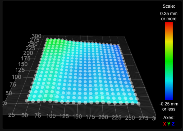
since I recalibrate probe at bed center, should't that point come back as zero in the bed mesh? I am not seeing that.