Cannot for the life of me figure out how to use M556
-
Hi everyone,
Long story short I’m struggling with not having perfect circles on a home made CoreXY machine. I’ve tried everything, and now the bots are tight and equal, the motion of the carriages on the smooth rods are super smooth, accelerations and jerk settings are very low so the only thing left to do in my head is square the frame.
Unfortunately that is not a solution at the moment and I wanted to use orthogonal axis compensation.
I have no idea how it works. I printed the parts and have the S parameter, but how do I get the x y z Paramus. I cannot find a single forum post or article on the internet explaining this and the old guide from reprappro is no more. My values are large like 6.3 my vs the 0.7mm I see floating around.
-
Somebody archived the reprappro.com site. If you go to the Ormerod section of the forum at reprap.org, there is a thread there about it.
Duet WiFi hardware designer and firmware engineer
Please do not ask me for Duet support via PM or email, use the forum
http://www.escher3d.com, https://miscsolutions.wordpress.com -
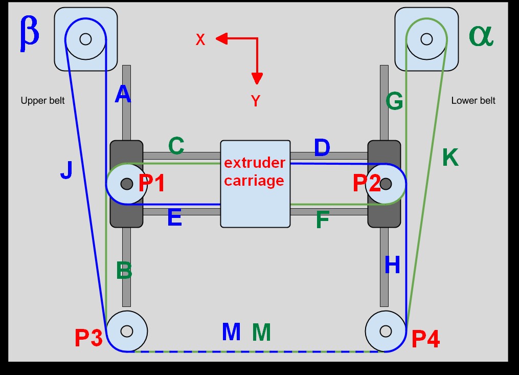
Can you post a photo of the XY mechanism? Distorted prints are a common problem if the belts are not aligned parallel to the guide rails. M556 won't fix that.
In the picture, belt segments labeled A-H must all be parallel to their respective guide rails/axes or belt tension will vary with extruder carriage position and prints will be distorted, especially as the carriage moves further away from the center of the range of motion in X and Y.
See this for an extreme example of how not to do it...
This is how the belts should look:
A few other quick checks: make sure you are using identical motors (or at least the same steps/rev), have the same steps/mm value assigned to both X and Y axes, and that both motors have drive pulleys with an equal number of teeth! You wouldn't be the first to put a 16 tooth pulley on one motor and a 20 tooth pulley on the other!
Building a coreXY mechanism is an exercise in symmetry above all else...
-
TBH, I doubt if Orthogonal misalignment is the reason for your less than perfect circles but working purely from memory, I think this is how it works.
You print a test piece which is essentially a kind of 3D right angle, or 3 right angles. So you have a cube say about 10mm in Y by 10mm in Z by say 120 mm in X. Then at right angles to that, starting at the same origin, you have a cube 10mm in X by 10mm in X by 120mm in Y. Then a further cube 10mm in X, by 10mm in Y by 120mm in Z. So you should end up with 3 right angles, XY, XZ and Y Z. Then you mark each leg at say 100mm from the origin. That becomes your S value (100 in this case). Then you get a true square, offer it up to the test piece and measure the distance from the square to the test piece at the 100mm mark. Do this for al 3 axes and put those numbers into M556.
Like I said, I'm working purely from memory from a 2 or 3 years ago when I built my RepRapPro Mendel and at my age, memory isn't the most reliable faculty.
-
@dc42 thanks! I’ll dive deeper, the first quick search I did didn’t seem to bring anything up.
-
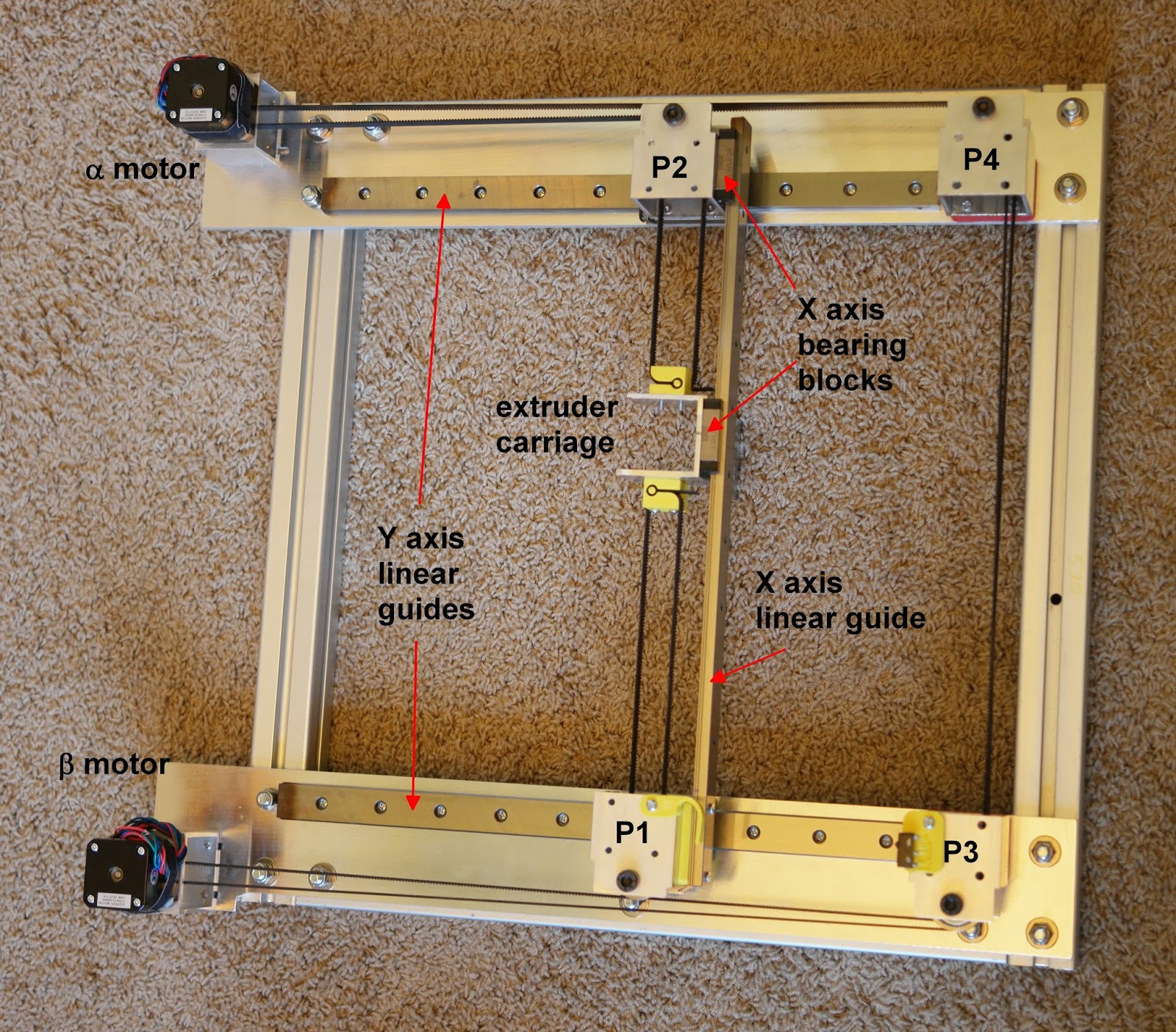
@mrehorstdmd I’ve attached a pic of my mechanism. The belts seem to be parallel. However, I haven’t tried printing my circle test model at different points on the bed to see how positioning, and therefore different belt tension in places would affect them.

It’s in a rougher shape now as I’m troubleshooting.Below I’ve also attached a pic of the circles.

-
It may be because of the camera angle, but section of the belt at top left of the first image between the stepper motor and the Y carriage looks like it may not be parallel to the rod.
-
The belts look pretty close to parallel to me, but the print looks over extruded, but closer look finds gaps between every other solid fill line. It looks like the extruder lays down a line, then doesn't shift far enough when it comes back along that line creating excessive overlap and then it moves over to lay down the next line and that leaves a gap. That implies some backlash in the mechanism. Are the belts tight and approximately equal in tension?
The extruder carriage looks pretty narrow- is there any play in the carriage -does it wiggle on the guide rails? Grab the hot-end and try to wiggle it. Check for play in the Y axis bearings, too. Nothing should wiggle.
-
@mrehorstdmd said in Cannot for the life of me figure out how to use M556:
The belts look pretty close to parallel to me, but the print looks over extruded, but closer look finds gaps between every other solid fill line. It looks like the extruder lays down a line, then doesn't shift far enough when it comes back along that line creating excessive overlap and then it moves over to lay down the next line and that leaves a gap. That implies some backlash in the mechanism. Are the belts tight and approximately equal in tension?
The extruder carriage looks pretty narrow- is there any play in the carriage -does it wiggle on the guide rails? Grab the hot-end and try to wiggle it. Check for play in the Y axis bearings, too. Nothing should wiggle.
Thanks! I think I might have found it, there was wiggle in the Y idlers. The x carriage, even though it’s tiny, is quite stiff so I think it’s fine.
That should explain the over/underextrusion on the model.
@dc42 said in Cannot for the life of me figure out how to use M556:
It may be because of the camera angle, but section of the belt at top left of the first image between the stepper motor and the Y carriage looks like it may not be parallel to the rod.
Hmm, I’m not sure either. I took everything apart to fix the y idlers which had a bit of wiggle in them. I’ll be careful for that when I re assemble.
Thanks for all the replies!
-
Good! I hope that fixes it.