[not yet solved] Tevo Little Monster DuetWifi errors
-
@rafb I think at home my tray is not really Top Top.
I have to find a glass to try to see if I can print a larger area.
What annoys me the most is the problem of limit stop. -
yes the problem of endstop optical is a known problem with the duet. This is probably what leads to the problem of geometry and therefore the impossibility of having a suitable first layer. I have a borosilicate glass and I use a Thickness Gage to adjust the space between my nozzle and the boro glass bed. My bed is on 3 spring.
I really have a hard time understanding? Having a 350mm bed to print pieces of max 100mm drives me crazy !! -
@rafb said in [solved] Tevo Little Monster + DuetWiFi + DuetTouch7" errors:
yes the problem of endstop optical is a known problem with the duet.
What problem are you referring to? The only problem I am aware of is that some optical endstops are designed to work with a 5V supply and don't work properly on 3.3V. The common ones can be fixed by changing one resistor (the one that feeds the IR emitter in the slotted opto switch). If it is an SMD resistor, soldering another resistor on top (to connect it in parallel) is easier because then you don't need to remove the old one.
-
The optical ones supplied with the TLM work just fine with the Duet as is (well mine do) and I have a few spare ones that also work fine, it's just that the led switches on and off so fast that could be confusing you.
-
Never mind... I reopen the 3d. Unlucky. After age of attempts I'm still here


As I have changed so many parts for reach more accuracy I still can't find a barely good calibration.If I try to manually to calibrate the printer following this video :
https://www.youtube.com/watch?v=Xk7remEhUx8
I reach some good stuffs , but absolutely not perfect and still full of mistakes.I noticed: i could accomplished to make a perfect equilibrium of calibration in front of the 3 tower using the screws on the cartridge.
So now if I run this 3 commands.
G28
G1 X-121.24 Y-70.00 Z0 F5000 - tower X
G28
G1 X121.24 Y-70.00 Z0 F5000 - tower Y
G28
G1 X0 Y140 Z0 F5000 - tower ZI can reach all the points at the same distance from the bed.
Hurra!!! I though... WTF , absolutely not.
If from the center G1 X0Y0Z0 , I go to X-100 the nozzle press toooo much against the bed. Fine , maybe the radius culprit ? Is settled as the original parameter as the rods as all the rest.After i found the "right" offset for the 3 towers I left to zero the M666.
Now the drama, if I move the nozzle in the points in front of the tower all is good , but 5cm on the left or right all is wrong. No matter I try to change slightly in radius or rods DAMN !!!!!
So the last resort:
The last resort was the AUTO calibration. BUT HELL if that was able to adjust a thing ! All the time produce uneven results.
I tried all the permutation on the Esher bed generator. Tried all the factor from 3 to 9. NOTHING make that damn bed flat and perpendicular to the towers.
Few point or all the possible to use.
The auto cal change the end-stop offset despite is the only thing that seems to manually work. Dramatically declinate the bed. (this was the FIRST problem I face of when I start to calibrate this devil machine)
The H parameters are not useful . They change the height JUST and exactly in the points mentioned and dont declinate all the bed.
I hoped that setting up the offset manually I could help the auto calibration to make a better result for the bed inclination . BUT NO. NOTHING.So, I'm lost (not in space but in my house looking this metal trap) .
I mounted the nema 17 , 09 degree and properly settled in :
; Motors 0.9 degree
M569 P0 S1 ; Drive 0 goes forwards
M569 P1 S1 ; Drive 1 goes forwards
M569 P2 S1 ; Drive 2 goes forwards
M569 P3 S0 ; Drive 3 goes forwards
M350 X16 Y16 Z16 E16 I1 ; Configure microstepping with interpolation
M92 X160 Y160 Z160 E920 ; Set steps per mm
M566 X1200 Y1200 Z1200 E1200 ; Set maximum instantaneous speed changes (mm/min)
M203 X18000 Y18000 Z18000 E1200 ; Set maximum speeds (mm/min)
M201 X1000 Y1000 Z1000 E1000 ; Set accelerations (mm/s^2)
M906 X1800 Y1800 Z1800 E1800 I60 ;I changed the belt with the ones with iron cores for less stretch and more accuracy.
They are well tied . All sound pretty the same (they sound more or less "like" a"Mi" of a guitar)
The carriages are shimmed with Teflon for avoid torsion ad it work damn fine.
All the structure is pretty sturdy.
The glassed custom build made by a professional industry have tolerance in order of cents.I have even tried to rise the bed using springs. I thought : if the automatic calibration see my bed declinate I'll correct manually the inclination of the bed. SOOOOOOOOOO ?!?! The auto calibration no matter what end declinate the bed !!!!!


NOW: I noticed something that some good souls could interpret for give me a light spot.
1)If I go to G1 Z0.2 (just for dont touch the bed) and then I move the head to X-100 , when turn to X0 the nozzle dig on the glass. As it was unable to turn in the same position. (belt tied much more or much less dont make difference - motor are at full power and very well cooled)
2)Without the automatic calibration the movements stay consistent inside the 100 radius (more or less). But between 100 and 140 the nozzle rise also of 0.2 (near). I suppose this is the effector shift . but it is really tiny till 100 and rise much more from 100 to 140. I'm avoiding 150/155 because the rising became much more evident.
3)When manually i Try to rise 0,05 sometime those commands are not received. I have to push twice the command for make one result.
When I press the button I can ear different sound form the motor. As first a whistle and then the movement. (the belt are tied , but I suppose that for a so tiny movement maybe tolerances of reverting the turn of the belts are the culprit? ) The motor are set to 1800mA and 160 micro steps.Any suggestion apart throw everything from the windows?
ps: the Akismet spam filter is REALLY annoying (even if I just want correct a typo), no other alternatives ?
-
It sounds like you still have mechanical issues, I would check that all 6 rods are the same length to start with, use a set square to check that all 3 tower's are square to each other and the bed, please read this guide. TLM Ultimate Calibration Tutorial.pdf
-
bouldnuts thanks for the support. I'll read that document deeply and for several times. As you linked it several post above. I have to dismantle the printer and check as stated in the document. I have all the tool for do that.
At the end did you changes for a smart effector with ball bars? Or you finally found a good calibration?
Did your frame or bars had uneven issue?Probably the linear rail with smart effector and ball bars could finally stop this damnation.

-
I have heard that the carbon rod's on these printer's can be out in relation to each other by quite a lot, so check them first before spending any money.
-
Fine , It will be the first check. TNX again.
-
Dear absolute !!!! Maybe you nailed it !

Look at this , the six rods:
1> -0.25
2> -0.25
3> -0.15
4> longhest
5> -0.1
6> -0.6 !!!!!!!!!!!!!!!!!!!!
Poor auto calibration , It cant reach those parameters.
From the Duet guide (and your linked pdf too):
https://duet3d.dozuki.com/Wiki/Calibrating_a_delta_printer
All 6 rods must be the same length, measured between bearing centersIf you are building the rods yourself, make them one by one in the same jig. If you are buying them, check that the supplier guarantees a maximum difference in rod length, which should be less than 0.1mm. It is particularly important that the rods in a pair are of matched lengths, because any difference will cause the effector to tilt.
I lost damn ages because I trusted the manufacturer
 REALLY My BAD
  ... I had should check this hundred time before all the attempt I made for calibrate it.
My mistake was : the product is already made , it will be good. Such a sheep.


Now what? Buy hundred of them to make sure found SIX equal ?!?!?!?!? Damn Tevo.
I feel so bad for wasted your time... All the people had helped here , damn ... sorry.
I should had to think as the printer was made by me and check ALL the steps as reported in the guide. Inexperience here docet.
Now I'll go check all the rest of the hardware hoping that the frame didnt have absurd variations
I'll keep you informed about the evolution of the story...
-
Finally got some material... (in Italy almost twice the price DAMN+shipment+taxes+taxes+taxes+taxes ecc ecc
)
400mm bars and effector , lets see if this trap can work properly...


I'm printing with an other printer the supports for the 3 plates...Thanks anyway at all that had participate and helped...
-
Here the adapters :
https://www.thingiverse.com/thing:2498606
I make all the 3 pieces identical in dimensions. D9.58mm , H30mm , L48mm.Trying to upload images (jpg)
Error
Input file contains unsupported image format -
Ah, when I told this frame is crap...finally got a long rule (1m) et voila' !!! All tower are bent but the z axis is the worst.
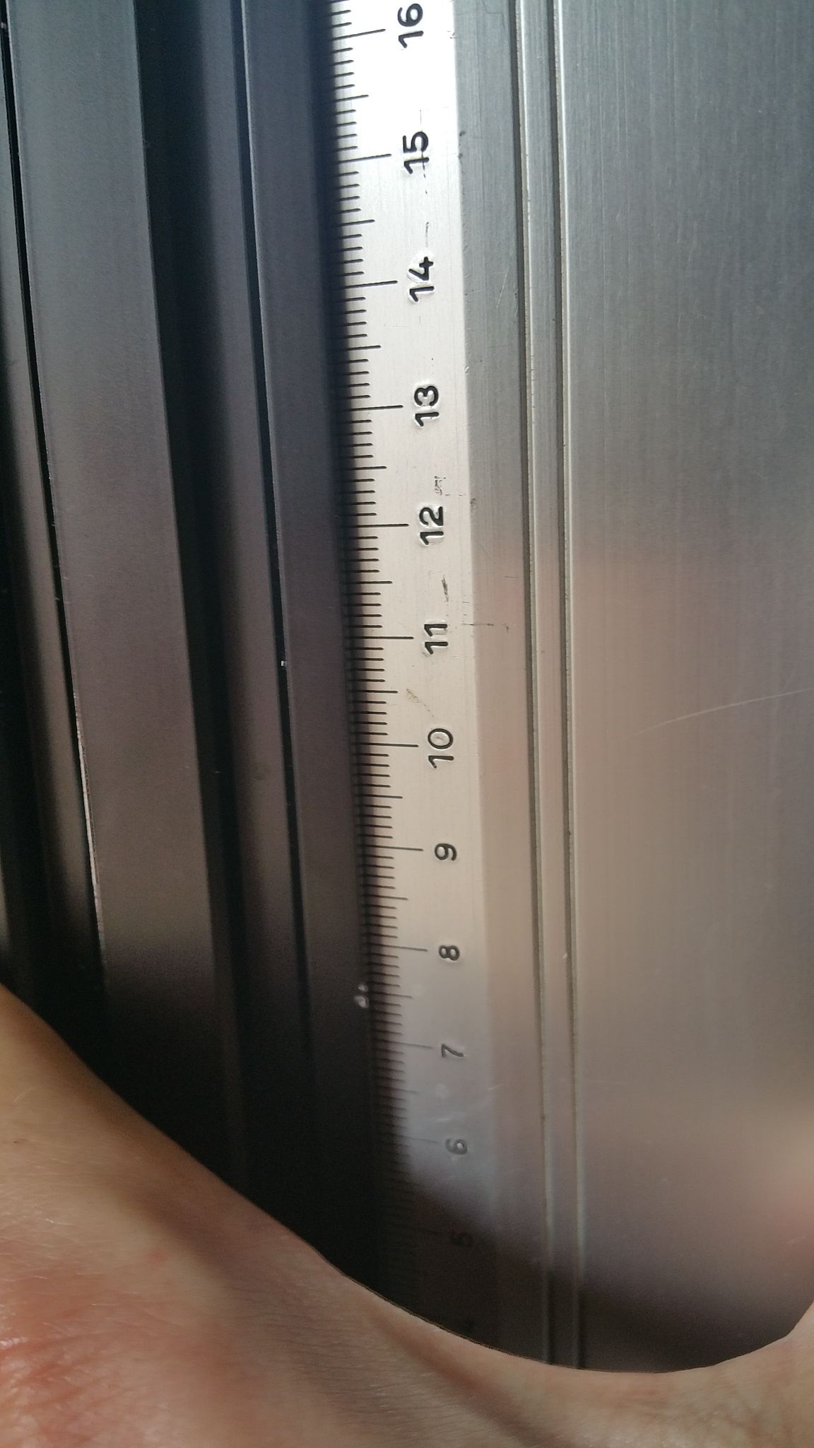
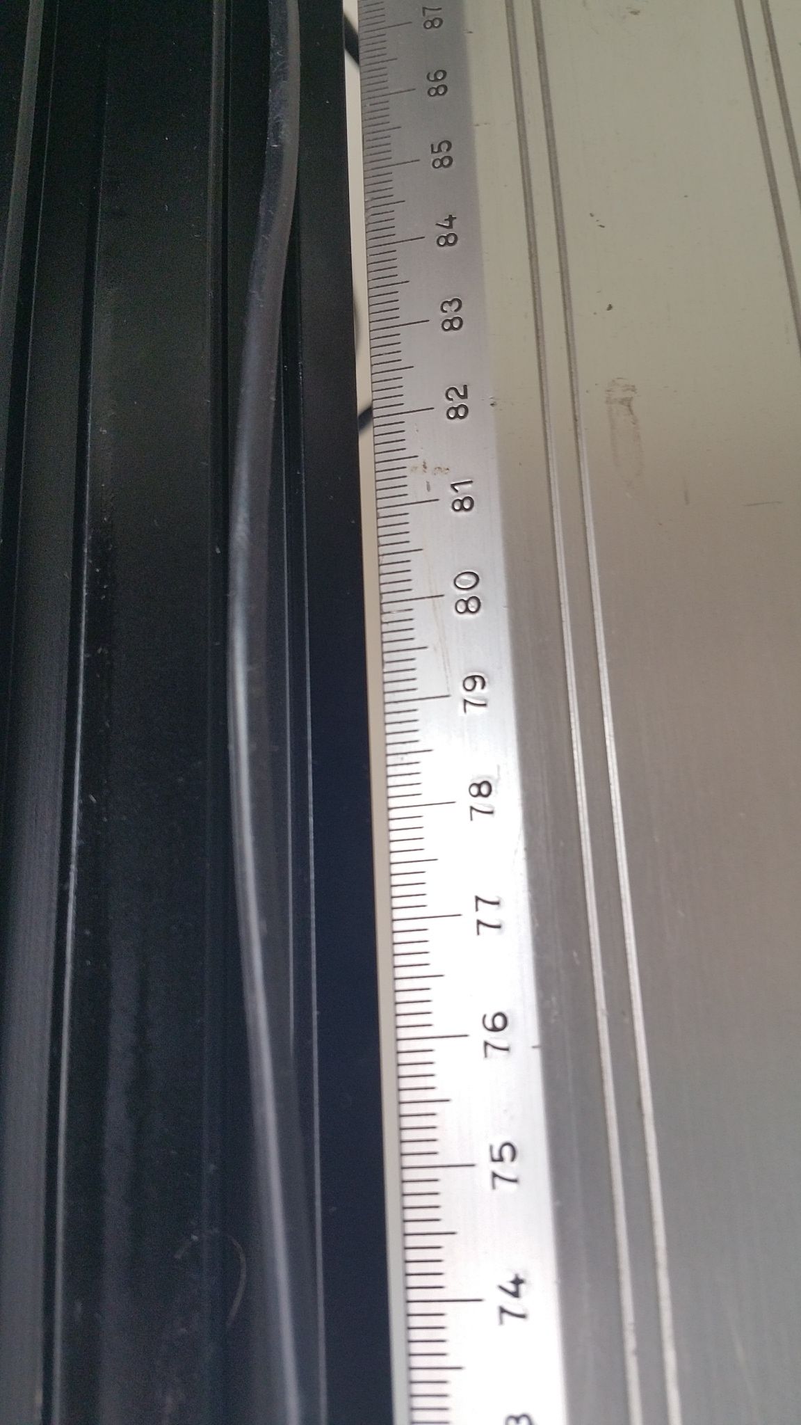
Just remain to build the frame by my self...damn.
Still here I can't believe such poor quality can be sold.