Flashforge Creator Pro Heat bed wiring
-
almost finished wiring of my Flashforge Creator Pro 2016. I am struggling with the Heat bed temp Sensor. I thought it was a thermistor, but there are 4pin connectors. On the bed, it says +3,3, GND and SIG (see picture) Where are the cables going in the duet? Can you give me a hint? Thanks a lot.

-
See:
https://groups.google.com/d/msg/flashforge/4lYQXPe_fA8/ga__vm05AwAJ
(flashforge google group) It'd be worth your while to read the entire thread at the link, as it chronicles me converting my FFCP to use a duet.Text at the link is:
Uh oh... For the HBP thermistor, it's 4 wires. I'm not sure how to handle that when most things only expect 2 wires for a thermistor. I know some specialized temp probes use 4 wires (PT100, for example), but this isn't supposed to be that fancy. Any suggestions? (Of course, I'll be googling as well...)
I believe two of them are ground or one is a "no connection". The
wiring is often an MPC-4 CD ROM audio connector. They are either 4
or 3 wires. For 3DP, the 3-wire variant is used. But you can use
the 4 wire variant as well: the 4th wire is just not connected to
anything.See this https://www.flickr.com/photos/d-newman/14557870172/in/album-72157645313526624/
-
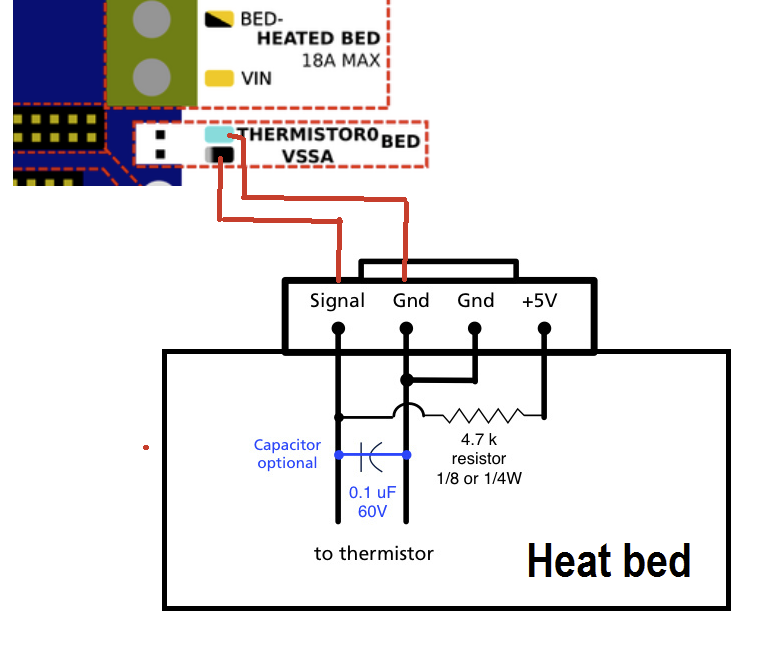
Thanks a lot, good thread. However, I am not that advanced yet in electronics, so I would like to check, if I can wire it like shown below? Or do I have to buy the OSH Park board?

-
The very next post in the thread I linked contained the following:
On the HBP thermistor: I found something that indicated that only pins 1 and 2 on the board are significant (numbering the pins left to right with the PCB printing face up.) It's the thermistor, so no polarity issues.
HBP: Heated Build Plate
PCB: Printed Circuit BoardHere's the tricky part, and the reason I can't (and won't) answer you directly: There are dozens of variants of the flashforge creator pro. Even "true" flashforge printers have changed parts over time - often without making much sense. There are labels on the PCB image you posted, but due to the angle I can't quite read one of them (starts with an "s") and can't figure out which pins are labeled what.
Most likely, the pin on the far side with the label that starts with an "S" is your SIG (signal) and the middle two pins are GND (ground.) If that's the case, you should be able to use the wires for the S and the adjacent ground.
If you have a multimeter, you can use it to verify which pins are the thermistor. (google for "how to use a multimeter to measure a thermistor")
-
@emax said in Flashforge Creator Pro Heat bed wiring:
Thanks a lot, good thread. However, I am not that advanced yet in electronics, so I would like to check, if I can wire it like shown below? Or do I have to buy the OSH Park board?
It may not matter, however I would swap the two red wires in your diagram, so that Signal goes to Thermistor0 and Gnd goes to VSSA.
-
 undefined Inlinebrother referenced this topic
-
Hi, did you succeed in your task to wire the bed thermistor?
Is it truly just a simple thermistor? that would be great -
I have the same image in my notes for my FFCP.
Here also is my config which should further confirm this:
; Heaters
M308 S0 P"temp0" Y"thermistor" T100000 B4066       ; configure sensor 0 as thermistor on pin temp0
M950 H0 C"out0" T0                                 ; create bed heater output on out0 and map it to sensor 0
M307 H0 R0.512 K0.276:0.000 D1.59 E1.35 S0.85 B1   ; enable bang-bang mode for the bed heater and set PWM limit
M140 H0                                            ; map heated bed to heater 0
M143 H0 S120                                       ; set temperature limit for heater 0 to 120C
Hope this helps you.
-
@misterjtc thank you, I couldn't wait for the answer so I checked that out myself and it worked)
And thanks for the config, I think I'll need that after I buy the cable to power the bed)
(because for some reason FYSETC Big Dipper clone of Duet 3 mini 5+ has separate bed power input)