Just to close the loop on this.
It was in fact an issue with my custom-made cable. I made a new cable taking a lot of care on my crimps and sealed both ends to hold everything tight and its working.
Just to close the loop on this.
It was in fact an issue with my custom-made cable. I made a new cable taking a lot of care on my crimps and sealed both ends to hold everything tight and its working.
I can confirm that following the instructions in the changelog that you linked to install AppArmor has corrected the issue.
Thank you @chrishamm !
@paulg4h is this still in the plans for 3.5 release? I am looking forward to having this functionality so I can plug in to home assistant.
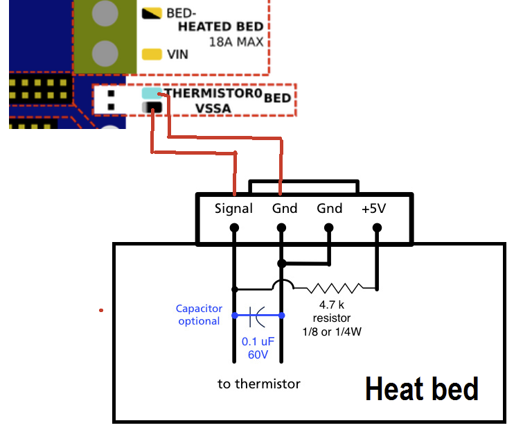
I have the same image in my notes for my FFCP.
Here also is my config which should further confirm this:
; Heaters
M308 S0 P"temp0" Y"thermistor" T100000 B4066       ; configure sensor 0 as thermistor on pin temp0
M950 H0 C"out0" T0                                 ; create bed heater output on out0 and map it to sensor 0
M307 H0 R0.512 K0.276:0.000 D1.59 E1.35 S0.85 B1   ; enable bang-bang mode for the bed heater and set PWM limit
M140 H0                                            ; map heated bed to heater 0
M143 H0 S120                                       ; set temperature limit for heater 0 to 120C
Hope this helps you.
So I am well on my way to getting the machine set-up but have run into an issue with one of my end stops that I can seem to figure out.
I have been working through the commissioning steps and am stuck at the end-stop portion. My X and Z end stops appear to function correctly during homing but I noticed some odd issues when the machine hit the Y-axis end-stop first. In testing the end stops with the M119 gcode I noted that the X and Z endstops register correctly via M119 but not the Y-axis stop. When the Y-axis stop is depressed, the machine registers that all three endstops are hit. Once removed, all end-stops register as not touched. I've went over my config a few times and changed IO ports but cannot get it sorted. Another thing I noticed during this testing is that the LED's on the end stops on the X and Z axes illuminate when pressed but the Y end-stop does not. I checked the wiring on the Y axis and even re-crimped the connectors.
My current config.g is below. Any advice or help is very much appreciated!
; Configuration file for Duet 3 Mini 5+ (firmware version 3.3)
; executed by the firmware on start-up
;
; generated by RepRapFirmware Configuration Tool v3.3.15 on Sat Jan 07 2023 21:50:31 GMT-0500 (Eastern Standard Time)

; General preferences
G90                                                ; send absolute coordinates...
M83                                                ; ...but relative extruder moves
M550 P"prometheus"                                     ; set printer name

; Drives
M569 P0.0 S1                                       ; physical drive 0.0 goes forwards
M569 P0.1 S1                                       ; physical drive 0.1 goes forwards
M569 P0.2 S0                                       ; physical drive 0.2 goes backwards
M569 P0.3 S1                                       ; physical drive 0.3 goes forwards
M569 P0.4 S1                                       ; physical drive 0.4 goes forwards
M584 X0.0 Y0.1 Z0.2 E0.3:0.4                       ; set drive mapping
M350 X16 Y16 Z16 E16:16 I1                         ; configure microstepping with interpolation
M92 X94.12 Y94.12 Z400.00 E96.2752:96.2752         ; set steps per mm
M566 X480.00 Y480.00 Z400 E1200.00:1200.00         ; set maximum instantaneous speed changes (mm/min)
M203 X6000.00 Y6000.00 Z180.00 E1200.00:1200.00    ; set maximum speeds (mm/min)
M201 X500.00 Y500.00 Z150.00 E250.00:250.00        ; set accelerations (mm/s^2)
M906 X810 Y810 Z300 E810:810 I20                   ; set motor currents (mA) and motor idle factor in per cent
M84 S30                                            ; Set idle timeout

; Axis Limits
M208 X-111 Y-75 Z0 S1                              ; set axis minima
M208 X150 Y75 Z150 S0                              ; set axis maxima

; Endstops
M574 X2 S1 P"!io0.in"                              ; configure switch-type (e.g. microswitch) endstop for high end on X via pin !io0.in
M574 Y2 S1 P"!io4.in"                              ; configure switch-type (e.g. microswitch) endstop for high end on Y via pin !io4.in
M574 Z1 S1 P"!io2.in"                              ; configure switch-type (e.g. microswitch) endstop for low end on Z via pin !io2.in

; Z-Probe
;M558 P0 H5 F0 T6000                              ; disable Z probe but set dive height, probe speed and travel speed
;M557 X15:135 Y15:60 S20                           ; define mesh grid

; Heaters
M308 S0 P"temp0" Y"thermistor" T100000 B4066         ; configure sensor 0 as thermistor on pin temp0
M950 H0 C"out0" T0                                 ; create bed heater output on out0 and map it to sensor 0
M307 H0 B1 S0.85                                   ; enable bang-bang mode for the bed heater and set PWM limit
M140 H0                                            ; map heated bed to heater 0
M143 H0 S120                                       ; set temperature limit for heater 0 to 120C
M308 S1 P"spi.cs1" Y"thermocouple-max31856"        ; configure sensor 1 as thermocouple via CS pin spi.cs1
M950 H1 C"out1" T1                                 ; create nozzle heater output on out1 and map it to sensor 1
M307 H1 B0 S1.00                                   ; disable bang-bang mode for heater  and set PWM limit
M143 H1 S280                                       ; set temperature limit for heater 1 to 280C
M308 S2 P"spi.cs2" Y"thermocouple-max31856"        ; configure sensor 2 as thermocouple via CS pin spi.cs2
M950 H2 C"out2" T2                                 ; create nozzle heater output on out2 and map it to sensor 2
M307 H2 B0 S1.00                                   ; disable bang-bang mode for heater  and set PWM limit
M143 H2 S280                                       ; set temperature limit for heater 2 to 280C

; Fans
M950 F0 C"out3" Q500                               ; create fan 0 on pin out3 and set its frequency
M106 P0 S0 H-1                                     ; set fan 0 value. Thermostatic control is turned off
M950 F1 C"out5" Q500                               ; create fan 1 on pin out5 and set its frequency
M106 P1 S1 H1 T45                                  ; set fan 1 value. Thermostatic control is turned on
M950 F2 C"out6" Q500                               ; create fan 2 on pin out6 and set its frequency
M106 P2 S1 H2 T45                                  ; set fan 2 value. Thermostatic control is turned on

; Tools
M563 P0 S"EXTRUDER RIGHT" D0 H1 F0                 ; define tool 0
G10 P0 X0 Y0 Z0                                    ; set tool 0 axis offsets
G10 P0 R0 S0                                       ; set initial tool 0 active and standby temperatures to 0C
M563 P1 S"EXTRUDER LEFT" D1 H2 F0                  ; define tool 1
G10 P1 X-34.04514634972721 Y0.29743029572304586 Z0 ; set tool 1 axis offsets
G10 P1 R0 S0                                       ; set initial tool 1 active and standby temperatures to 0C

; Custom settings are not defined

; Miscellaneous
M911 S10 R11 P"M913 X0 Y0 G91 M83 G1 Z3 E-5 F1000" ; set voltage thresholds and actions to run on power loss
I also tried to get the End-Stop add-in working but couldn't figure out what needs to be contained within the zip package. All my attempts ended with either nothing happening or a manifest error.
Secondly, my stepper motors are a bit noisy under certain conditions. The symptoms are below:
The steppers are configured based on other people's configs for the same printer (Flashforge Creator Pro).
I am looking for some advice on tuning these steppers better.
Thanks in advance!
I am having an issue with my Duet 3 Mini 5+ and RaspberryPi (SBC).
The issue: When the main board is powered off for some amount of time and then powered back on, the sbc (and duet web control) aren't able to remake the connection.
To set up the Raspberry Pi, I followed the guide outlined here (it is not setup using the offical DuetPi image): https://docs.duet3d.com/User_manual/Machine_configuration/DSF_Other
Steps to recreate the issue:
I am wondering if there is some timeout or specified number of reconnect attempts that needs to be adjusted?
Like I mentioned, if the main board is powered down for only a few minutes, when the power is restored, the connection between the SBC and duet main board is automatically reestablished. It seems like the mainboard board needs to be powered down for an extended period of time for the issue to present itself.
Any help is appreciated. Thanks in advance!
I have the same image in my notes for my FFCP.
Here also is my config which should further confirm this:
; Heaters
M308 S0 P"temp0" Y"thermistor" T100000 B4066       ; configure sensor 0 as thermistor on pin temp0
M950 H0 C"out0" T0                                 ; create bed heater output on out0 and map it to sensor 0
M307 H0 R0.512 K0.276:0.000 D1.59 E1.35 S0.85 B1   ; enable bang-bang mode for the bed heater and set PWM limit
M140 H0                                            ; map heated bed to heater 0
M143 H0 S120                                       ; set temperature limit for heater 0 to 120C
Hope this helps you.
I am here to close the loop on this in case anyone runs into a similar issue. Below is what I found.
nano /home/pi/.config/lxsession/LXDE-pi/autostart
Added the following to the autostart file:
@chromium-browser -start-fullscreen http://127.0.0.1/
I did not confirm on the official Duet3D image but I suspect the reason for no screen blanking is potentially because of using kiosk mode, but that is just an unsupported theory.
@andiwinter the content of the /boot/config.txt file is below but I assume its the other file it references that you are looking for. It is also shown below.
Contents of /boot/config.txt
pi@prometheus:/boot $ cat config.txt
DO NOT EDIT THIS FILE

The file you are looking for has moved to /boot/firmware/config.txt
Contents of /boot/firmware/config.txt
pi@prometheus:/boot/firmware $ cat config.txt
# For more options and information see
# http://rptl.io/configtxt
# Some settings may impact device functionality. See link above for details

# Uncomment some or all of these to enable the optional hardware interfaces
#dtparam=i2c_arm=on
#dtparam=i2s=on
dtparam=spi=on

# Enable audio (loads snd_bcm2835)
dtparam=audio=on

# Additional overlays and parameters are documented
# /boot/firmware/overlays/README

# Automatically load overlays for detected cameras
camera_auto_detect=1

# Automatically load overlays for detected DSI displays
display_auto_detect=1

# Automatically load initramfs files, if found
auto_initramfs=1

# Enable DRM VC4 V3D driver
dtoverlay=vc4-kms-v3d
max_framebuffers=2

# Don't have the firmware create an initial video= setting in cmdline.txt.
# Use the kernel's default instead.
disable_fw_kms_setup=1

# Disable compensation for displays with overscan
disable_overscan=1

# Run as fast as firmware / board allows
arm_boost=1

[cm4]
# Enable host mode on the 2711 built-in XHCI USB controller.
# This line should be removed if the legacy DWC2 controller is required
# (e.g. for USB device mode) or if USB support is not required.
otg_mode=1

[all]
@jay_s_uk I am using one of the raspberry pi official cameras. Not usb.
I recently had an SD card failure and did a fresh install of the latest pi image. I recovered my sys config files from github and everything appears to work as it did before except two things.
A few questions:
Additional info:
I thought there used to be an option in raspi-config to enable the legacy camera but this option seems to be gone. Is there no longer anything that needs to be done to enable access to the pi brand camera?
Here is what I get when I run "vcgencmd get_camera":
pi@prometheus:~ $ vcgencmd get_camera
supported=0 detected=0, libcamera interfaces=0
The above tells me that no camera is detected, but I have no idea why... Everything worked fine until I updated my sd card and pi image.
Here is the results from "journalctl -u duetpluginservice -f":
pi@prometheus:~ $ journalctl -u duetpluginservice -f
Jul 06 14:38:35 prometheus DuetPluginService[1572]: [info] DuetPluginService.Program: Plugin MotionWebcamServer loaded
Jul 06 14:38:35 prometheus systemd[1]: Started duetpluginservice.service - Duet Plugin Service.
Jul 06 14:38:35 prometheus DuetPluginService[1572]: [info] Plugin MotionWebcamServer: Process has been started (pid 1862)
Jul 06 14:38:36 prometheus DuetPluginService[1865]: [0:motion] [NTC] [ALL] conf_load: Processing thread 0 - config file /opt/dsf/sd/sys/motion.conf
Jul 06 14:38:36 prometheus DuetPluginService[1865]: [0:motion] [ALR] [ALL] conf_cmdparse: Unknown config option ""
Jul 06 14:38:36 prometheus DuetPluginService[1865]: [0:motion] [NTC] [ALL] Above message repeats 49 times
Jul 06 14:38:36 prometheus DuetPluginService[1865]: [0:motion] [NTC] [ALL] motion_startup: Logging to syslog
Jul 06 14:38:36 prometheus DuetPluginService[1865]: [0:motion] [NTC] [ALL] motion_startup: Motion 4.5.1 Started
Jul 06 14:38:36 prometheus DuetPluginService[1865]: [0:motion] [NTC] [ALL] motion_startup: Using default log type (ALL)
Jul 06 14:38:36 prometheus DuetPluginService[1865]: [0:motion] [NTC] [ALL] motion_startup: Using log type (ALL) log level (CRT)
Any advice is greatly appreciated!
@paulg4h is this still in the plans for 3.5 release? I am looking forward to having this functionality so I can plug in to home assistant.
I can confirm that following the instructions in the changelog that you linked to install AppArmor has corrected the issue.
Thank you @chrishamm !
@chrishamm thanks for the reply.
I apologize but I only have basic knowledge of this type of stuff. That changelog is pretty old and my Duet install is less than a month old. Therefore my install should already include AppArmor but I guess it doesn't?
It's not quite clear to me but it seems like you are telling me to install and configure AppArmor per that old change log?
Just to close the loop on this.
It was in fact an issue with my custom-made cable. I made a new cable taking a lot of care on my crimps and sealed both ends to hold everything tight and its working.