• Tags
  • Documentation
  • Order
  • Register
  • Login
Duet3D Logo Duet3D
  • Tags
  • Documentation
  • Order
  • Register
  • Login

PNP inductive not properly working

Scheduled Pinned Locked Moved Solved
Duet Hardware and wiring
5
18
1.3k
Loading More Posts
  • Oldest to Newest
  • Newest to Oldest
  • Most Votes
Reply
  • Reply as topic
Log in to reply
This topic has been deleted. Only users with topic management privileges can see it.
  • undefined
    dc42 administrators
    last edited by 2 Feb 2019, 12:25

    I think the resistor values are too high. When in digital mode, the Z probe input has a pullup resistor, nominally 100K but minimum 50K. It might work if you put it in analog mode (P1 in the M558 command).

    Duet WiFi hardware designer and firmware engineer
    Please do not ask me for Duet support via PM or email, use the forum
    http://www.escher3d.com, https://miscsolutions.wordpress.com

    1 Reply Last reply Reply Quote 0
    • undefined
      supermarioprof
      last edited by 2 Feb 2019, 15:11

      Sound strange, just verified: if I connect sensor to 12V external power supply I measure 0V when not triggered, 3.3V when triggered between signal (black wire) and GND (blue wire).

      Will have a try on M558 P1

      1 Reply Last reply Reply Quote 0
      • undefined
        supermarioprof
        last edited by 2 Feb 2019, 21:24

        You are right: lowering resistors to 10k and 34k (two 68k resistors in parallel) the inductive PNP NO sensor works as expected, digitally, setting M558 P5.

        FYI: it worked in analog mode too, with previous resistors and setting M558 P1

        1 Reply Last reply Reply Quote 0
        • undefined
          supermarioprof
          last edited by 2 Feb 2019, 21:26

          One more question: why does it work with lower resistor and not with higher ones? I would like to understand, anyone can share a simple scheme or drawing? I'm not so expert in electronics...

          1 Reply Last reply Reply Quote 0
          • undefined
            dc42 administrators
            last edited by dc42 2 Feb 2019, 21:31 2 Feb 2019, 21:31

            Because the internal pullup resistor (nominally 100K) is pulling the input up to +3.3V, so the value of your pulldown resistor to ground needs to be a lot lower than that, in order to hold the pin close to ground potential when your sensor is not triggered. In analog mode (M558 P1), the pullup resistor is turned off.

            Duet WiFi hardware designer and firmware engineer
            Please do not ask me for Duet support via PM or email, use the forum
            http://www.escher3d.com, https://miscsolutions.wordpress.com

            1 Reply Last reply Reply Quote 0
            • undefined
              pedro schmidt @supermarioprof
              last edited by 29 Jul 2020, 09:47

              @supermarioprof I'm about to do the same install. would you be able to share your schematic as I just want to physically see the schematic and double check everything is correct. Don't really want to blow up my duet. thanks

              undefined 1 Reply Last reply 29 Jul 2020, 10:26 Reply Quote 0
              • undefined
                droftarts administrators @pedro schmidt
                last edited by 29 Jul 2020, 10:26

                @pedro-schmidt It's described here https://duet3d.dozuki.com/Wiki/Connecting_a_Z_probe#Section_PNP_output_normally_open_inductive_or_capacitive_sensor but there's no wiring diagram.

                Ian

                Bed-slinger - Mini5+ WiFi/1LC | RRP Fisher v1 - D2 WiFi | Polargraph - D2 WiFi | TronXY X5S - 6HC/Roto | CNC router - 6HC | Tractus3D T1250 - D2 Eth

                undefined 1 Reply Last reply 29 Jul 2020, 11:20 Reply Quote 1
                • undefined
                  pedro schmidt @droftarts
                  last edited by 29 Jul 2020, 11:20

                  @droftarts thanks, i got to that page as well. the above diagram for the NPN there is only one resistor in there. would that be the same for the PNP? thanks again

                  undefined undefined 2 Replies Last reply 29 Jul 2020, 11:22 Reply Quote 0
                  • undefined
                    pedro schmidt @pedro schmidt
                    last edited by 29 Jul 2020, 11:22

                    @pedro-schmidt said in PNP inductive not properly working:

                    @droftarts thanks, i got to that page as well. the above diagram for the NPN there is only one resistor in there. would that be the same for the PNP? thanks again

                    FYI i'm running the duet 2 wifi 3.1

                    1 Reply Last reply Reply Quote 0
                    • undefined
                      droftarts administrators @pedro schmidt
                      last edited by 29 Jul 2020, 11:28

                      @pedro-schmidt said in PNP inductive not properly working:

                      would that be the same for the PNP?

                      No, the sensors are different. Follow the guide for PNP. If you have a multimeter, check the output voltage before connecting it to the Duet, to avoid releasing the magic smoke.

                      Ian

                      Bed-slinger - Mini5+ WiFi/1LC | RRP Fisher v1 - D2 WiFi | Polargraph - D2 WiFi | TronXY X5S - 6HC/Roto | CNC router - 6HC | Tractus3D T1250 - D2 Eth

                      undefined 1 Reply Last reply 29 Jul 2020, 11:36 Reply Quote 1
                      • undefined
                        pedro schmidt @droftarts
                        last edited by 29 Jul 2020, 11:36

                        @droftarts sure thing. thanks for the heads up. i'll check the output voltage when i get home. just to clarify i should have 0V when NOT triggered and 3.3V WHEN triggered? as mentioned above by @supermarioprof .

                        undefined ? 2 Replies Last reply 29 Jul 2020, 11:47 Reply Quote 0
                        • undefined
                          droftarts administrators @pedro schmidt
                          last edited by 29 Jul 2020, 11:47

                          @pedro-schmidt I haven't tested a PNP sensor, so I'm not sure. But the voltage range should be 0V to 3.3V. Doesn't matter which way, because you can always invert the signal with '!', eg M558 P5 C"!zprobe.in" H5 F120 T3000

                          Note that if you have a Duet 2 Wifi, board revision v1.4 or later, the probe.in pin is 30V-tolerant, which makes the wiring easier. Just make sure you get it on the right pin, though! See the Note at the end of the guide for PNP, as you still need a pulldown resistor.

                          Ian

                          Bed-slinger - Mini5+ WiFi/1LC | RRP Fisher v1 - D2 WiFi | Polargraph - D2 WiFi | TronXY X5S - 6HC/Roto | CNC router - 6HC | Tractus3D T1250 - D2 Eth

                          1 Reply Last reply Reply Quote 1
                          • ?
                            A Former User @pedro schmidt
                            last edited by A Former User 29 Jul 2020, 12:37

                            The PNP sensor will normally drive the output to its supply voltage when triggered (6-24v normally, maybe 5v). When not triggered the output is floating, meaning it needs a pull down resistor to have a defined state of 0v when not triggered. (The sensor can be NO or NC, but this can be inverted in configs as pointed out)

                            7f67c3b3-bb04-4618-81d5-a4d464f5568a-image.png

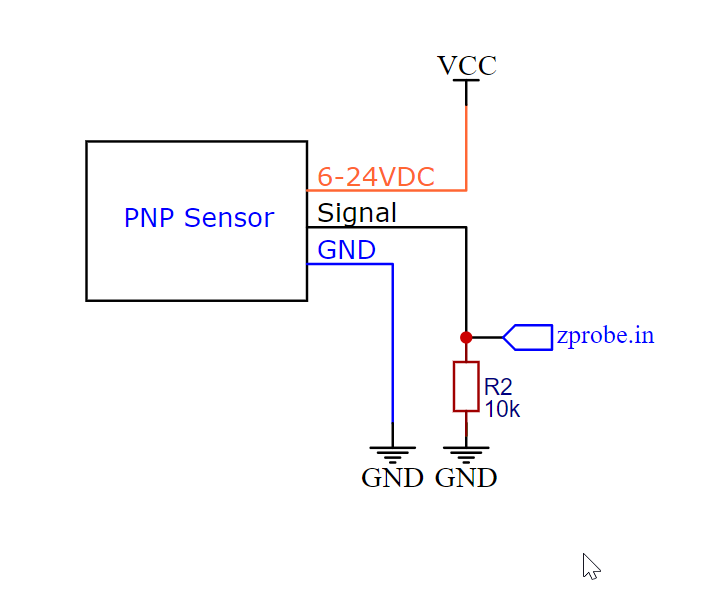
                            if you're going to use the endstop input, then the input is still 30V tollerant but the LEDs in prefer 8v so a voltage divider as described in the link above is a good idea. (replace R1 with 20k if using 12v)
                            318537a6-ec65-4283-9c9c-c6a72852d7d3-image.png

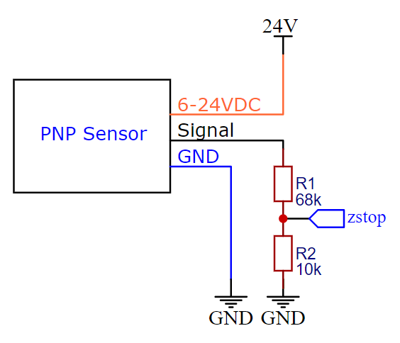
                            edit forgot link to led caveat. @duet ppl pngs of various combinations here: pnp_zprobe.zip if you want to update the wiki,

                            undefined undefined 2 Replies Last reply 29 Jul 2020, 13:20 Reply Quote 3
                            • undefined
                              droftarts administrators @A Former User
                              last edited by 29 Jul 2020, 13:20

                              @bearer Thanks for the diagrams, I'll add them to the wiki!

                              Ian

                              Bed-slinger - Mini5+ WiFi/1LC | RRP Fisher v1 - D2 WiFi | Polargraph - D2 WiFi | TronXY X5S - 6HC/Roto | CNC router - 6HC | Tractus3D T1250 - D2 Eth

                              1 Reply Last reply Reply Quote 1
                              • undefined
                                pedro schmidt @A Former User
                                last edited by 29 Jul 2020, 13:26

                                @bearer great stuff. i'm not stupid but i do like to see the diagram. its very clear now. thanks to everyone. i'll update you later on, hopefully with a successful install. cheers

                                ? 1 Reply Last reply 29 Jul 2020, 13:33 Reply Quote 0
                                • ?
                                  A Former User @pedro schmidt
                                  last edited by 29 Jul 2020, 13:33

                                  @pedro-schmidt said in PNP inductive not properly working:

                                  @bearer great stuff. i'm not stupid but i do like to see the diagram. its very clear now. thanks to everyone. i'll update you later on, hopefully with a successful install. cheers

                                  no worries; people are different - i.e I've always preferred listening to reading/watching (and with Ian adding one to the wiki maybe the next guy finds it easier as well)

                                  the most important part with those sensors are making sure it does what it says on the tin, especially if the lower end sensors from amazon/ebay/etc. incorrect marking/ colour coding or defective units do occur. luckily the duet with its 30v tolerant inputs are more rugged than most boards though.

                                  1 Reply Last reply Reply Quote 1
                                  • First post
                                    Last post
                                  Unless otherwise noted, all forum content is licensed under CC-BY-SA