MPSCARA G28: Intermediate position outside machine limits
-
G1 S2 X0 Y0
M114
X:199.070 Y:0.000 Z:4.000 E0:0.0 E1:0.0 E2:0.0 E3:0.0 E4:0.0 E5:0.0 E6:0.0 E7:0.0 E8:0.0  Count 0 0 10240 Machine 199.070 0.000 4.000
G1 S2 X0 Y90
M114
X:98.388 Y:100.660 Z:4.000 E0:0.0 E1:0.0 E2:0.0 E3:0.0 E4:0.0 E5:0.0 E6:0.0 E7:0.0 E8:0.0  Count 0 2581 10240 Machine 98.388 100.660 4.000
The values are not exactly X200/Y0, X100/Y100 since I edited the arm lengths according to the Marlin configuration that's been made available by the original designer. The proximal arm length is 98.41, and the distal arm length is 10.6, so the values match.
-
Looks good! Is movement working correctly now?
-
I can now issue moves, but I don't get straight lines, only arcs.
I have modified my kinematics with some initial offsets so I stop crashing the distal arm into the proximal arm ... it seems like the A... and B... limits are not used to limit motion (I also entered an erroneous
G1 S2 X6060once, and the arm promptly tried to do 6060 degrees of counterclock movement, which was stopped by the robot's base of course). The current kinematics definition isM669 K4 P98.41 D100.66 A-108:108 B-108:0 X160 Y-150; setup SCARA kinematicshere are the results from trying to reach the four corners of my currrently defined bed:
G0 X0 Y0
M114
X:-15.497 Y:14.529 Z:4.000 E0:0.0 E1:0.0 E2:0.0 E3:0.0 E4:0.0 E5:0.0 E6:0.0 E7:0.0 E8:0.0 Count -1071 -329 10240 Machine -15.497 14.529 4.000
G0 X0 Y300
MM114
X:-15.497 Y:285.471 Z:4.000 E0:0.0 E1:0.0 E2:0.0 E3:0.0 E4:0.0 E5:0.0 E6:0.0 E7:0.0 E8:0.0 Count 1404 -329 10240 Machine -15.497 285.471 4.000
G0 X40 Y300
G0 X40 Y0
M114
X:-1.540 Y:268.845 Z:4.000 E0:0.0 E1:0.0 E2:0.0 E3:0.0 E4:0.0 E5:0.0 E6:0.0 E7:0.0 E8:0.0 Count 1223 -329 10240 Machine -1.540 268.845 4.000
G0 X0 Y0
M114
X:-15.497 Y:14.529 Z:4.000 E0:0.0 E1:0.0 E2:0.0 E3:0.0 E4:0.0 E5:0.0 E6:0.0 E7:0.0 E8:0.0 Count -1071 -329 10240 Machine -15.497 14.529 4.000
Further tests show that if I "re-center" the printer with
G1 S2 X0 Y0, I reach different locations depending on whether I did a move before re-centering or not, or whether I combine X and Y moves.I am trying to plot this so I can show rather than tell, but it's a bit difficult. See the attached photo for some nice arcs that depend on whether I send a
G0 Xn Ym, orG0 XnandG0 Ymseparately
-
here are some more tests:
G28; includes G1 S1 X0Y0 -- marked A in the picture
M114
X:39.070 Y:150.000 Z:0.000 E0:0.0 E1:0.0 E2:0.0 E3:0.0 E4:0.0 E5:0.0 E6:0.0 E7:0.0 E8:0.0  Count 0 0 0 Machine 39.070 150.000 0.000
G0 Y0 ; marked B in the picture
M114
X:-1.807 Y:30.801 Z:0.000 E0:0.0 E1:0.0 E2:0.0 E3:0.0 E4:0.0 E5:0.0 E6:0.0 E7:0.0 E8:0.0  Count -895 -329 0 Machine -1.807 30.801 0.000
G0 Y300; marked C in the picture
M114
X:-16.267 Y:286.288 Z:0.000 E0:0.0 E1:0.0 E2:0.0 E3:0.0 E4:0.0 E5:0.0 E6:0.0 E7:0.0 E8:0.0  Count 1413 -329 0 Machine -16.267 286.288 0.000
G0 Y150 ; distal arm crashed due to blockage of end stop trigger block on distal arm -- circled in the picture
M114
X:-16.267 Y:150.000 Z:0.000 E0:0.0 E1:0.0 E2:0.0 E3:0.0 E4:0.0 E5:0.0 E6:0.0 E7:0.0 E8:0.0  Count 1273 -2511 0 Machine -16.267 150.000 0.000
-
Did you add the C parameter to the M669 command, that I said I thought you needed in my earlier response?
-
I must have inadvertedly removed that while I was trying to find sensible offsets for X and Y ...
C-1:0:0brings me one step closer, but is not perfect yet. There seems to be some elliptical effect for X moves still that gets more pronounced the more the arm is away from the middle of the bed (i.e., the position afterG1 S2 X0 Y0). Y moves are still very much arcs, but now the positions from absolute G0 moves match what DWC reports.This is mostly visible in longer moves (more than 2-5mm), so maybe it's irrelevant for my use case where individual moves will most certainly be shorter. I tried to play with the S and T parameters, but I don't know what reasonable values would look like.
Another observation is that only
G0 ...moves work, whereasG1 ...moves fail with "intermediate position outside machine limits" -- I guess this is because G1 is special with SCARA kinematics ...G1 S2 ...still works to set proximal/distal arm angles. I guess the error message is for the usual case of people trying to move beyond axis limits, and not for people that try to do angle-based moves while in a distance-based coodinate system ...Also, final observation: If you set a value at the second or third factor of M669 C, your Z motor will keep going even if you hit the Z endstop. Don't do that (-:
-
@oliof said in MPSCARA G28: Intermediate position outside machine limits:
C-1:0:0brings me one step closer, but is not perfect yet. There seems to be some elliptical effect for X moves still that gets more pronounced the more the arm is away from the middle of the bed (i.e., the position afterG1 S2 X0 Y0). Y moves are still very much arcs, but now the positions from absolute G0 moves match what DWC reports.This is mostly visible in longer moves (more than 2-5mm), so maybe it's irrelevant for my use case where individual moves will most certainly be shorter. I tried to play with the S and T parameters, but I don't know what reasonable values would look like.
Are you referring to G0 moves or to G1 moves? G0 moves will always be curved.
If G1 moves are curved, then the M669 parameters are not correct for your machine. In particular:
-
The distal arm homing angle must be accurate. RRF assumes the distal arm position when the distal homing switch is triggered is either the first or second B parameter, depending on whether you have a high or low end stop position configured in M574. As I recall, you home with the proximal and distal arms in a straight line, so the distal angle is zero, which is why one of your B values is zero. But are the arms exactly in a straight line? If not then you will need to adjust that B value to be the actual angle. For example, if the distal arm is slightly rotated anticlockwise with respect to the proximal arm, then that B value should be slightly positive.
-
The proximal and distal arm lengths must be correctly configured. The proximal arm length is measured between the proximal and distal bearing centres. The distal arm length is measured from the distal arm centre to the nozzle.
You may find it helpful to read section "Calibration" at https://miscsolutions.wordpress.com/2017/08/27/converting-the-robotdigg-scara-printer-to-duet-electronics/.
Another observation is that only
G0 ...moves work, whereasG1 ...moves fail with "intermediate position outside machine limits" -- I guess this is because G1 is special with SCARA kinematics ...G1 S2 ...still works to set proximal/distal arm angles.G1 moves will succeed if the initial position, final position, and all intermediate positions are within the limits you set using M208 and are also reachable. Note, the position after homing the arms is considered to be just outside the reachable area. So at the end of your homing file, use a G0 move to put the head within the reachable area.
Also, final observation: If you set a value at the second or third factor of M669 C, your Z motor will keep going even if you hit the Z endstop. Don't do that (-:
Yes, because those 2 parameters tell the firmware what effect the proximal and distal motors have on the Z height. This is needed for printers such as the Helios.
-
-
All my tests were with G0 moves; if they're supposed to be arcs, then G0 moves work as intended (-:
I believe arms are homed correctly and arm lengths are correct as well. I will try moving inside the reachable area and then do more tests with G1 moves.
Thanks for your patience and support!
-
@dc42 said in MPSCARA G28: Intermediate position outside machine limits:
G1 moves will succeed if the initial position, final position, and all intermediate positions are within the limits you set using M208 and are also reachable. Note, the position after homing the arms is considered to be just outside the reachable area. So at the end of your homing file, use a G0 move to put the head within the reachable area.
OK, so, the following works as well as the mechanical build of this SCARA allows (the arm sags terribly for a number of reasons, my limited ability to build precisely being the premier one).
I extended my homeall.g to do
G1 S2 X0 Y0 F5000; move arm to center position.
; move to (0,0) so we can do G1 moves
G1 S2 X-60 Y60; move into printable area
G0 X0 Y0; move to zero point
And then I was able to draw some squares and a diagonal:
G1 X32 Y0 F300
G1 X32 Y32 F300
G1 X0 Y32 F300
G1 X0 Y0 F300
G1 X40 Y0 F300
G1 X40 Y40 F300
G1 X0 Y40 F300
G1 X0 Y0 F300
G1 X48 Y0 F300
G1 X48 Y48 F300
G1 X0 Y48 F300
G1 X0 Y0 F300
G1 X64 Y64 F300
The result:

So, apart from the wobble, which is mostly due to bad construction, this looks pretty decent. I don't think it's worth spending more time on this particular robot, but I found a version where the motors act as counterweights to the arm, which should give me a chance at better quality. That build does not include fixtures for the end stops, but I should be able to re-use the one I have (or build something similar to what I have.
-
I'm glad you got it working.
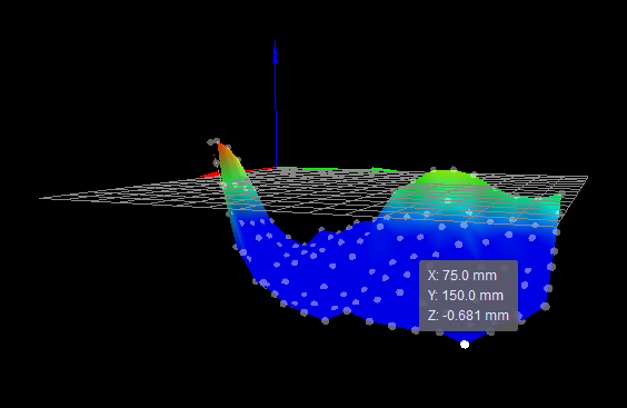
My own SCARA machine suffers from arm sag too. Here's the height map reported by G29:

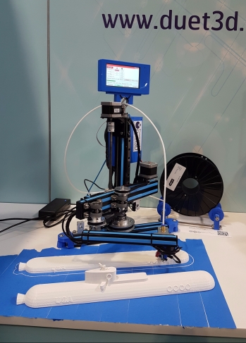
So I use mesh bed compensation and it prints reasonably well:

The submarine is 400mm long.
-
I haven't even begun thinking about implementing a Z probe ... but I did read the (expired) patent on correcting for kinematics errors on SCARA arms.
PS: The submarine is 400mm long, no?
-
Yes 400mm - I've corrected it.
I wasn't aware of that patent. I described how I calibrated my SCARA robot in the "Calibration" section of my blog entry at https://miscsolutions.wordpress.com/2017/08/27/converting-the-robotdigg-scara-printer-to-duet-electronics/.
-
Cool, I will try your macros (should be easier for me using just a pen) to see how far off I am from the actual values.
-
 undefined JoergS5 referenced this topic