Duet3D Logo Duet3D
    • Tags
    • Documentation
    • Order
    • Register
    • Login
    1. Home
    2. tombrazier
    • Profile
    • Following 0
    • Followers 0
    • Topics 1
    • Posts 83
    • Best 24
    • Controversial 0
    • Groups 0

    tombrazier

    @tombrazier

    37
    Reputation
    18
    Profile views
    83
    Posts
    0
    Followers
    0
    Following
    Joined Last Online

    tombrazier Unfollow Follow

    Best posts made by tombrazier

    • RE: Formulas behind the emf-calculator

      @dc42 and @chrishamm thank you for the EMF calculator. I was busy replicating this work when I found it.

      I think I have found several errors in the calculations of the "Speed at which torque starts to drop" values. (Just to give some credence to what I suggest below it might be helpful to know I am a Marlin dev.)

      • When calculating revsTorqueDropLowSlip and revsTorqueDropHighSlip I think just dividing speed by the number of motors is incorrect. Instead, the value of supplyVoltage should be divided by the number of motors. i.e. motors in series form a potential divider for the supply voltage. An easy way to test my assertion is to consider what happens with two motors in series when resistance * motorCurrent > supplyVoltage / 2. That should result in "n/a" because the voltage cannot even drive the requested current through the two winding resistances. But, instead, the web page just halves the speeds.
      • driverVoltageDrop is double counted. It is incorporated when voltageDrop is calculated and then, later, when revsTorqueDropLowSlip and revsTorqueDropHighSlip are calculated, it is added on to voltageDrop again.
      • revsTorqueDropHighSlip is missing voltageDrop in two places. This formula is the result of applying the quadratic formula to solve for revs in the equation supplyVoltage = sqrt( (revs * inductiveBackEmfPerRevSec)^2 + (revs * motionBackEmfPerRevSec + voltageDrop)^2 ). This expands to0 = revs^2 * inductiveBackEmfPerRevSec^2 + revs^2 * motionBackEmfPerRevSec^2 + 2 * revs^2 * motionBackEmfPerRevSec * voltageDrop + voltageDrop^2 - supplyVoltage^2. The b coefficient in this equation is 2 * motionBackEmfPerRevSec * voltageDrop and it is this voltageDrop which is lost when the quadratic formula is applied to calculate revsTorqueDropHighSlip.
      posted in General Discussion
      tombrazierundefined
      tombrazier
    • RE: Hollow shaft extruder

      Hi all, I made the VDE-100 video that has been referenced a few times. I have been using the VDE-100 for a long time now and I love it. Several comments in response to the thread above:

      @nikscha your maths was correct, tan(15) * 1.75 * pi is the theoretical thread pitch. In reality the knife edges tend to drag a bit through the filament resulting an a somewhat lower pitch.

      Loading/unloading is pretty easy but, yes, it is done by instructing the extruder stepper to turn. I have my whole VDE-100 assembly attached via a quick release clip which also helps because occasionally a blob on the end of the filament went retract through the extruder. And the quick release is super cool for dealing with nozzle clogs, etc.

      The extruder seems to just work on any filament (e.g. floppy TPU at one end of the scale and hard PLA at the other). But I think definitely avoid abrasive filament. I did print recently with GF filament and specifically swapped out my extruder for another that is not as nice as the VDE but has bondtech gears.

      There have been suggestions about tensioning. I played around a lot with tensioning ideas, including using a similar idea to @nikscha's printed spokes. In the end, it just is not needed. The knife edges cut into the filament and that provides the tension. But it does mean you need fairly precise diameters @o_lampe. Since I found a way to cut those even with rudimentary tools, I am satisfied with that. Of course, you also need precise filament diameters, but that's pretty much a given these days.

      Steppers getting hot: with the VDE-100 the stepper stays nice and cool because there is so little torque needed and so not much current is needed. I would think Ingenuity would have the same benefit.

      Filament twisting in the VDE-100: this is surprisingly far less of a problem than you'd think. The melted plastic in the nozzle provides a fair back torque. And the shorter the part through the heatsink, the better this effect is. Once again, though, precision edge diameter is key. Cut too far into the filament and that creates more torque.

      VDE files to play with: I published my files with FreeCAD model on printables.com.

      posted in General Discussion
      tombrazierundefined
      tombrazier
    • RE: Hollow shaft extruder

      My latest VDE design is even better than the one I used for the 16 minute benchy. It features two pairs of flanged bearings mounted back to back plus a plain bearing.

      20230809_111142.jpg

      I'd like to experiment with three pairs of flanged bearings but need to buy more bearings before I can do that.
      Here are some graphs to give an idea of how different designs are affected by compression of the helical thread:

      Screenshot_2023-08-09_11-44-42.png

      Y is thread pitch / theoretical thread pitch and X is actual linear extrusion speed in mm/s (i.e. taking compression into account).

      • The baseline is what I was using when this thread started. It has two chisel edged bearings and a plain bearing and is extruding through a traditional 0.5mm nozzle.
      • The red line has larger bearings with knife edges (i.e. a / shape rather than a |/ shape). Both of these reduce compression effects. These are lower quality bearings and I believe this accounts for the red line performing worse at low speeds.
      • The yellow line replaces the nozzle with a 0.4mm CHT clone from aliexpress which I have modified to enlarge the three holes so that there is a sharp edge in the middle rather than a flat face. These clone CHT nozzles actually increase back pressure at low flow rates but they do not have the sudden drop off at around 6mm/s.
      • The green line is the extruder I used for my 16 minute benchy. It replaces the plain bearing with a knife edge bearing so it has three knife edges rather than 2.
      • The last line is my latest experiment with 2 pairs of back to back knife edged bearings. This is slightly better and is the only extruder where I have been able to extrude at an instructed 12mm/s (and getting 8.54mm/s) without the compression causing the knife edges to start falling into the wrong helical thread path, causing inconsistent extrusion.
      posted in General Discussion
      tombrazierundefined
      tombrazier
    • RE: Formulas behind the emf-calculator

      Ah, bother, there is an error in one of my formulae and akismet won't let me correct it. The third bullet point should have "This expands to..." with 2 * revs * motionBackEmfPerRevSec * voltageDrop in the middle of the equation (where revs is not squared).

      posted in General Discussion
      tombrazierundefined
      tombrazier
    • EMF calculator bugs

      @chrishamm @dc42 Did you see my comments about errors in the EMF calculator in this forum topic?

      Posting a new topic just in case you didn't.

      posted in General Discussion
      tombrazierundefined
      tombrazier
    • RE: Hollow shaft extruder

      Success! I've finally completed a 16 minute benchy with my VDE extruder. Somewhat under-extruded in places, but pretty good considering. The rest of the machine hardware is also pretty low spec. 12V bedslinger running on an 8 bit AVR mainboard. Posted a video on youtube.

      That's been a long-running project. Glad to put it to bed.

      Next up: a new VDE idea to try with 3 pairs of flanged bearings. (And @o_lampe then I'll send three of the bearings to you. It was while I was grinding them that it occurred to me that three extra bearings might be an interesting thing to test!)

      posted in General Discussion
      tombrazierundefined
      tombrazier
    • RE: Hollow shaft extruder

      Hi guys, I have been on holiday for a few week, hence the radio silence.

      Nice work from several of you.

      @zero-K how does your extruder do?

      @breed Your pressure bearings that aren't canted will probably be fine with many filaments. Quite some time back I tried a VDE-100 with only plain bearings (i.e. no edge) and it had very little grip. I think that was with PLA. I conclude that filament slides over plain bearings very easily. Something like TPU might be a different matter, though.

      @o_lampe I got the carriers, thanks. Now I have my work cut out for me grinding bearings! On the plus side, one of the users on the 3D Printing discord server is working on a Dremel attachment to help with this.

      posted in General Discussion
      tombrazierundefined
      tombrazier
    • RE: Hollow shaft extruder

      @rqthree Rip and I have collaborated extensively on VDE. By which I mean I have second guessed pretty much everything he has done, tried it myself and generally found that he was right after all!

      posted in General Discussion
      tombrazierundefined
      tombrazier
    • RE: Hollow shaft extruder

      Some updates from me...

      I have experimented further with the LDO motor. For everything other than ridiculously fast printing it's great. The primary limitations I have found are that continuous current much above about 600mA will eventually cause it to get too hot for PLA and at any current E jerk needs to remain quite low (e.g. max 7mm/s) for the VDE which has quite a high steps/mm ratio. On the other hand it has great acceleration and speed, I can get 1000mm/s/s even with the high step/mm count of VDE and top speed is about 60mm/s (with no load) and over 10mm/s driving filament into the hot end.

      One day I might figure out how to get TMC CoolStep to help with the current. And I have dreams of implementing a jerk-less version of Linear Advance in Marlin which would pretty much remove the jerk limit as an issue.

      In other news, I have uploaded a video about the bearing grinder jig.

      And, further news, with a PLA printed carrier the 3 back-to-back bearing pairs version of the extruder seems to work pretty well. I have used a bite of 0.07mm for this version. @o_lampe it works a lot better than with your printed carriers which leaves me wondering whether something like material flexibility might be an issue. I am also coming to the conclusion that it's best to grind the bearings first and then measure them and print a carrier to match their edge diameter. That's a lot easier than grinding an edge down to the exact diameter.

      posted in General Discussion
      tombrazierundefined
      tombrazier
    • RE: Hollow shaft extruder

      @o_lampe said in Hollow shaft extruder:

      With all due respect, but grinding an edge to a flanged bearing is not my favorite evening activity

      Really? Why? 😁

      If you can work out a way of self adjusting I'd be very interested to see it. I didn't really follow the conversation above. I need a picture, I think.

      posted in General Discussion
      tombrazierundefined
      tombrazier

    Latest posts made by tombrazier

    • RE: Can you take a look at this accelerometer measurement?

      @claustro I think the image of the calibration pattern is rotated 90°. Assuming that is correct then the Y calibration is the line on the left and the X calibration is the line on the bottom.

      It looks like there is pretty much no resonant frequency in the range 0Hz to 90Hz for Y and the X resonant frequency is about 4/5 of the way along the line at just over 70Hz.

      Important question: was input shaping disabled when you ran the test?

      posted in Tuning and tweaking
      tombrazierundefined
      tombrazier
    • RE: Hollow shaft extruder

      @CNCModeller Sorry I have been busy elsewhere and didn't see your questions.

      I know you've bought bearings now but, for reference, here are some considerations for flanged bearings:

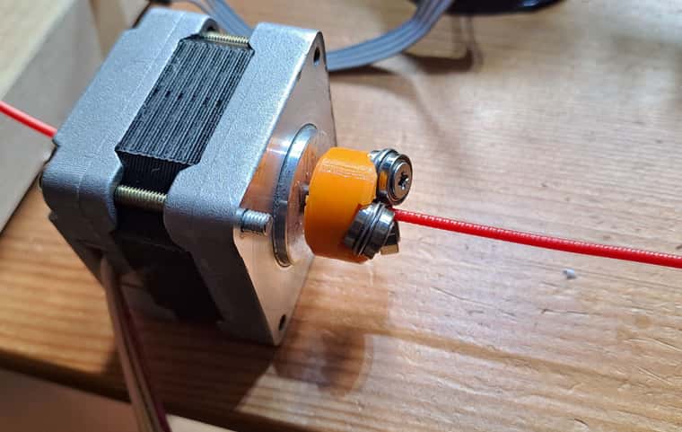
      • OD of the part touching the filament needs to be about 9mm or less. i.e. that's the diameter of the flange or just the OD for any non-flanged bearings. Larger than 9mm and the bearings start interfering with each other.
      • @rqthree uses extended-race bearings which helps with mounting on his machined carriers. I don't bother as I use printed carriers and it is easy to print a bezel on which the race mounts.
      • It is possible to use a mix of different size bearings. My best extruder has two MF95ZZ bearings which have a 10mm flange. To avoid interference I use a smaller third bearing and mount the three of them slightly non-symmetrically around the filament axis. The slightly larger bearings have more grip.
      • Depending on which country you're in, metric or imperial may be easier to source.

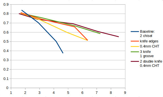
      I, like @rqthree, have found a 0.1mm bite to be about perfect. More than that and it increases drag. Less than that and it both reduces thrust and also makes the tolerances much tighter, e.g. something like a 0.02mm error is a much bigger proportion of a 0.05mm bite than of 0.1mm.

      There is nothing particularly special about 9.1mm. It's what I was targeting when I made my videos because it was about 0.1mm smaller than the diameter of the unground flange and I wanted to take off as little material as possible. Realistically, I could have gone for 9.15mm. My primary considerations for diameter are:

      • Less grinding takes less time and effort and leaves fewer chances for machining errors.
      • You can always take more off if necessary but you can't put it back on, so aim for larger and adjust to smaller if need be. e.g. if you want the same diameter for all the bearings and one accidentally ends up a bit smaller you can then make the others smaller too.
      • I have found that larger diameters grip the filament better. I am guessing this is because the bite has a different shape with a bit more overlap.
      • As @rqthree says, if you are printing your carrier then it's easier to make a custom carrier for whatever sizes you ended up grinding the bearings.

      Drag on the filament is minimal as long as the bite is small enough. @rqthree initially designed a counter-torque mechanism into his extruder but later found it was not needed. The back-torque provided by the melted filament in the nozzle is sufficient. I benefited from this knowledge and have never even implemented a counter-torque. You do see a bit of backlash and it varies a bit by filament type. You may find retraction distances benefit from a bit of re-tuning. But I have not found it affects the print. Obviously consistent filament diameter becomes an important factor, but any decent filament these days has fine tolerances. It also helps if you minimise the path length through the hotend heatsink as this decreases the springiness of the filament section between the extruder and the nozzle.

      Speed: there are a couple of guys on the CroXY Discord server who are exploring using VDE for high-speed. The simplicity and weight considerations are just too tempting. At high enough speeds VDE does under-extrude. There can also be issues with having to run the motor hotter which is problematic with the filament running through the shaft. More flanged bearings definitely help under-extrusion but they add drag and increase the likelihood of multiple grooves making a mess of each other. A mix of larger and smaller bearings mounted asymmetrically is also helpful. Firmware can help a bit as well, Marlin now has nonlinear extrusion and I think someone (@oliof maybe) said that RRF has has this feature for ages. Possibly Klipper does as well, I don't know. The guys at CroXY are, I think, experimenting with drilling a larger hole in the motor shaft and lining it with PTFE tubing. Mounting the motor on the hotend heatsink and sharing cooling air with the heatsink is also something to explore.

      One idea I may go back to one day is a two bearing VDE. This required the filament path to be constrained by the walls of the hole leading up to the bearings, so adds friction, but it would allow for much larger bearings without any risk of interference.

      @rqthree's observations about using PLA for a printed carrier match my experience. I have not experimented widely here but in my best round of testing I did swap from PETG to PLA when I noticed there was a difference.

      posted in General Discussion
      tombrazierundefined
      tombrazier
    • RE: Hollow shaft extruder

      @oliof said in Hollow shaft extruder:

      @rqthree "being done is a decision" that must be made. Kudos!

      Yeah, rq3's comments struck a chord with me too.

      posted in General Discussion
      tombrazierundefined
      tombrazier
    • RE: Hollow shaft extruder

      Some updates from me...

      I have experimented further with the LDO motor. For everything other than ridiculously fast printing it's great. The primary limitations I have found are that continuous current much above about 600mA will eventually cause it to get too hot for PLA and at any current E jerk needs to remain quite low (e.g. max 7mm/s) for the VDE which has quite a high steps/mm ratio. On the other hand it has great acceleration and speed, I can get 1000mm/s/s even with the high step/mm count of VDE and top speed is about 60mm/s (with no load) and over 10mm/s driving filament into the hot end.

      One day I might figure out how to get TMC CoolStep to help with the current. And I have dreams of implementing a jerk-less version of Linear Advance in Marlin which would pretty much remove the jerk limit as an issue.

      In other news, I have uploaded a video about the bearing grinder jig.

      And, further news, with a PLA printed carrier the 3 back-to-back bearing pairs version of the extruder seems to work pretty well. I have used a bite of 0.07mm for this version. @o_lampe it works a lot better than with your printed carriers which leaves me wondering whether something like material flexibility might be an issue. I am also coming to the conclusion that it's best to grind the bearings first and then measure them and print a carrier to match their edge diameter. That's a lot easier than grinding an edge down to the exact diameter.

      posted in General Discussion
      tombrazierundefined
      tombrazier
    • RE: Hollow shaft extruder

      @rqthree I vote we call this push pull version VDE337.

      posted in General Discussion
      tombrazierundefined
      tombrazier
    • RE: Hollow shaft extruder

      @o_lampe said in Hollow shaft extruder:

      Is that the retraction speed or can you actually extrude at 50mm/s? What are actual PLA print speeds with 0.4mm nozzle and say 0.3mm layer?

      That's retraction speed. I think the motor can move at that speed while printing without stalling (but will have to confirm for sure). However with compression of the helical thread actual extrusion speed will be a whole lot lower. I specced the motor for extruding about 16mm/s which would give about 320mm/s linear printing speed with 0.4mm x 0.3mm lines. However with nozzle back-pressure I don't expect to get 16mm/s.

      posted in General Discussion
      tombrazierundefined
      tombrazier
    • RE: Hollow shaft extruder

      I have finally had a chance to play about with all the new toys.

      The 3 x double bearing idea doesn't work very well in my tests so far. I have found that with a 0.1mm bite depth the torque applied on the filament is too large. Reducing the bite depth to 0.07mm helps but the grip is a lot worse than the best I have seen with other configurations. This is using the SLA printed carriers. One test left to do for a definite change-only-one-variable test would be to print a carrier myself in PLA. But my guess is that won't improve matters and so it's not high on my priority list.

      The SLA carrier with three single bearings with 9.1mm edges works fairly well in printing but I have not had time to test it extensively.

      The LDO motors work nicely, but running them at their rated current of 1A RMS they get way too hot. I have found that 700mA RMS is acceptable if room temperature is low enough - they get about 30°C hotter than ambient. At 700mA I can drive the filament at 50mm/s and accelerate at 1500mm/s^2 without a motor stall. Jerk speed is 7mm/s (this is relevant for linear advance in Marlin and, I think, for the equivalent in RRF).

      20231023_123232.mp4

      Total extruder mass is 53g. It is a drop-in replacement for my 39mm Nema 17 style motor because the mounting hole spacing is the same as the diagonal distance between Nema 17 holes. I just had to print a smaller holding clamp.

      20231023_123541.jpg

      posted in General Discussion
      tombrazierundefined
      tombrazier
    • RE: Hollow shaft extruder

      @rqthree Rip and I have collaborated extensively on VDE. By which I mean I have second guessed pretty much everything he has done, tried it myself and generally found that he was right after all!

      posted in General Discussion
      tombrazierundefined
      tombrazier
    • RE: Hollow shaft extruder

      @o_lampe Looks really good. The filament should be constrained as soon as possible after leaving the extruder. Can you get some PTFE tube in there?

      posted in General Discussion
      tombrazierundefined
      tombrazier
    • RE: Hollow shaft extruder

      I vaguely think someone asked me to grind some bearings for them some time back, but can't remember who. If it was anyone here, can you remind me?

      posted in General Discussion
      tombrazierundefined
      tombrazier