Duet3D Logo Duet3D
    • Tags
    • Documentation
    • Order
    • Register
    • Login
    1. Home
    2. Snyggis 0
    • Profile
    • Following 0
    • Followers 0
    • Topics 5
    • Posts 20
    • Best 0
    • Controversial 0
    • Groups 0

    Snyggis 0

    @Snyggis 0

    0
    Reputation
    2
    Profile views
    20
    Posts
    0
    Followers
    0
    Following
    Joined Last Online

    Snyggis 0 Unfollow Follow

    Latest posts made by Snyggis 0

    • RE: 4 Z Axis Leadscrews

      @T3P3Tony Right, here it is. Thanks for the help!

      config.g

      ; Configuration file for RepRapFirmware on Duet 3 Main Board 6XD
      ; executed by the firmware on start-up
      ;
      ; generated by RepRapFirmware Configuration Tool v3.5.10 on Tue Feb 25 2025 19:08:55 GMT-0500 (Eastern Standard Time)
      
      ; General
      G90 ; absolute coordinates
      M83 ; relative extruder moves
      M550 P"BeltDriveFDM" ; set hostname
      M911 S19.8 R22 P"M913 X0 Y0 G91 M83 G1 Z3 E-5 F1000" ; set voltage thresholds and actions to run on power loss
      
      ; Network
      M552 P0.0.0.0 S1 ; configure Ethernet adapter
      M586 P0 S1 ; configure HTTP
      
      ; Wait a moment for the CAN expansion boards to become available
      G4 S2
      
      ; Smart Drivers
      M569 P1.0 S1 D2 ; driver 1.0 goes forwards (extruder 0)
      
      ; Motor Idle Current Reduction
      M906 I30 ; set motor current idle factor
      M84 S30 ; set motor current idle timeout
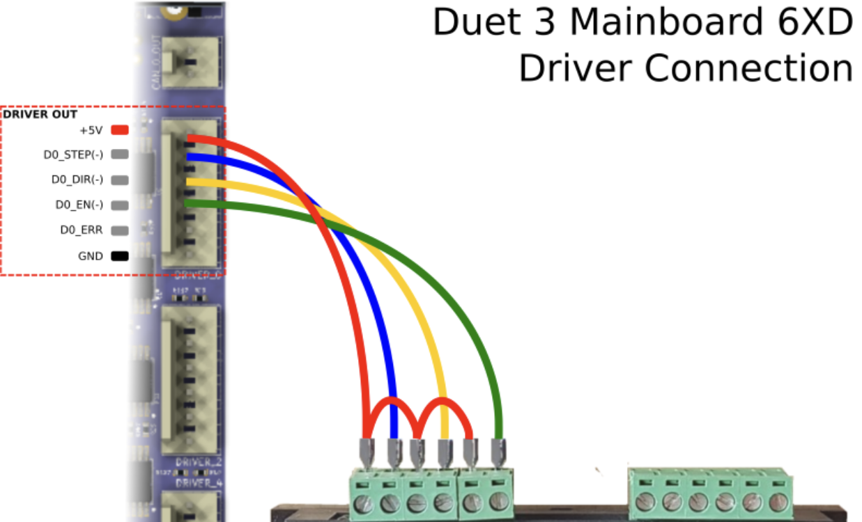
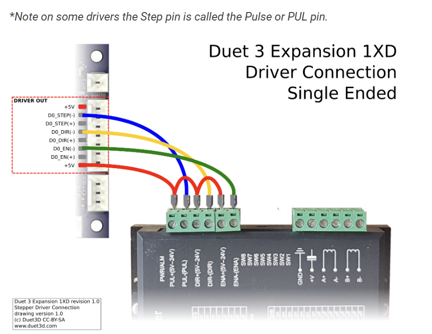
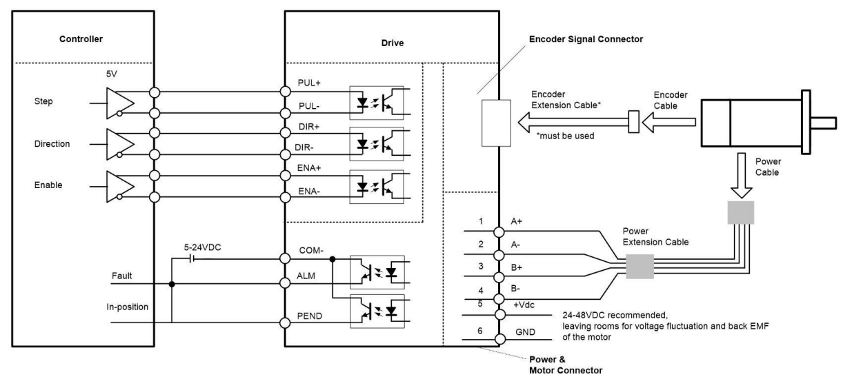
      
      ; External Drivers
      M569 P0.0 S1 R0 T5:5:10:0 ; driver 0.0 goes forwards and requires an active-low enable signal (X axis)
      M569 P0.1 S1 R0 T5:5:10:0 ; driver 0.1 goes forwards and requires an active-low enable signal (Y axis)
      M569 P0.2 S1 R0 T5:5:10:0 ; driver 0.2 goes forwards and requires an active-low enable signal (Y axis)
      M569 P0.3 S0 R0 T5:5:10:0 ; driver 0.3 goes backwards and requires an active-low enable signal (Z axis)
      M569 P0.4 S0 R0 T5:5:10:0 ; driver 0.4 goes backwards and requires an active-low enable signal (Z axis)
      M569 P0.5 S0 R0 T5:5:10:0 ; driver 0.5 goes backwards and requires an active-low enable signal (Z axis)
      M569 P122.0 S0 R0 T5:5:10:0 ; driver 122.0 goes backwards and requires an active-low enable signal (Z axis)
      
      ; Axes
      M584 X0.0 Y0.1:0.2 Z0.3:0.4:0.5:122.0 ; set axis mapping
      M350 X16 Y16 Z16 I0 ; configure microstepping without interpolation
      M92 X80 Y80 Z400 ; configure steps per mm
      M208 X0:200 Y0:200 Z0:200 ; set minimum and maximum axis limits
      M566 X900 Y900 Z12 ; set maximum instantaneous speed changes (mm/min)
      M203 X6000 Y6000 Z366 ; set maximum speeds (mm/min)
      M201 X500 Y500 Z20 ; set accelerations (mm/s^2)
      
      ; Extruders
      M584 E1.0 ; set extruder mapping
      M350 E16 I1 ; configure microstepping with interpolation
      M906 E1000 ; set extruder driver currents
      M92 E420 ; configure steps per mm
      M566 E120 ; set maximum instantaneous speed changes (mm/min)
      M203 E3600 ; set maximum speeds (mm/min)
      M201 E250 ; set accelerations (mm/s^2)
      
      ; Kinematics
      M669 K0 ; configure Cartesian kinematics
      
      ; Probes
      M558 K0 P9 C"1.io3.in" H5 F120 T6000 ; configure BLTouch probe via slot #0
      G31 P500 X0 Y0 Z0.7 ; set Z probe trigger value, offset and trigger height
      M950 S0 C"1.io0.out" ; create servo #0 for BLtouch
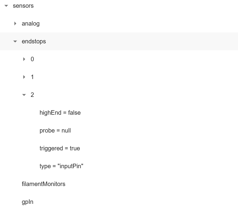
      
      ; Endstops
      M574 X1 P"io0.in" S1 ; configure X axis endstop
      M574 Y1 P"io1.in+io2.in" S1 ; configure Y axis endstop
      M574 Z2 P"io3.in+io4.in+io5.in+io6.in" S1 ; configure Z axis endstop
      
      ; Sensors
      M308 S0 P"temp0" Y"thermistor" A"Heated Bed Z1" T100000 B4725 C7.06e-8 ; configure sensor #0
      M308 S1 P"1.temp0" Y"thermistor" A"Nozzle" T100000 B4725 C7.06e-8 ; configure sensor #1
      M308 S2 P"temp1" Y"thermistor" A"Heated Bed Z2" T100000 B4725 C7.06e-8 ; configure sensor #2
      
      ; Heaters
      M950 H0 C"out0" T0 ; create heater #0
      M143 H0 P0 T0 C0 S140 A0 ; configure heater monitor #0 for heater #0
      M307 H0 R2.43 D5.5 E1.35 K0.56 B0 ; configure model of heater #0
      M950 H1 C"1.out0" T1 ; create heater #1
      M143 H1 P0 T1 C0 S285 A0 ; configure heater monitor #0 for heater #1
      M307 H1 R2.43 D5.5 E1.35 K0.56 B0 ; configure model of heater #1
      M950 H2 C"out1" T2 ; create heater #2
      M143 H2 P0 T1 C0 S285 A0 ; configure heater monitor #0 for heater #2
      M307 H2 R2.43 D5.5 E1.35 K0.56 B0 ; configure model of heater #2
      
      ; Heated beds
      M140 P0 H0 ; configure heated bed #0
      
      ; Fans
      M950 F0 C"out3" ; create fan #0
      M106 P0 S0 L0 X1 B0.1 ; configure fan #0
      M950 F1 C"out4" ; create fan #1
      M106 P1 S0 B0.1 H1 T45 ; configure fan #1
      
      ; Tools
      M563 P0 D0 H1 F0 ; create tool #0
      M568 P0 R0 S0 ; set initial tool #0 active and standby temperatures to 0C
      
      
      posted in Firmware installation
      Snyggis 0undefined
      Snyggis 0
    • RE: 4 Z Axis Leadscrews

      Uploading my config, I made a few changes today. Still struggling with the same problem.configtool 2-25-25.json

      posted in Firmware installation
      Snyggis 0undefined
      Snyggis 0
    • RE: 4 Z Axis Leadscrews

      When I hook the sensor into the X input, I can see the state change for Endstop "0", when I trigger any of the Z endstops I would expect to see something happen on Endstop "2" but nothing happens. It doesnt matter which of the Z endstops I trigger, nothing happens.

      posted in Firmware installation
      Snyggis 0undefined
      Snyggis 0
    • RE: 4 Z Axis Leadscrews

      @dc42 Hi there,

      When I navigate in as you suggest, it does not show the individual sensors for Z. Please see below:
      6b6e1cfe-48a4-4653-8a3f-df818139cd29-image.png

      posted in Firmware installation
      Snyggis 0undefined
      Snyggis 0
    • RE: 4 Z Axis Leadscrews

      @dc42

      I am attaching my config file. I was able to assign all of the axis with their appropriate end stops. At this point I am trying to test the switches before I run the homing routine.

      configtool 2-21-25.json

      Because I have 4 on the z axis, I dont see how to check them individually. I tried all the steps in the commissioning guide, but cant see how it would apply to multiple switches on one axis? I can trigger the X just fine and see it working, but the other ones dont seem to be working.

      Please let me know if I need to attach the whole config file.

      Thanks!

      Scott

      posted in Firmware installation
      Snyggis 0undefined
      Snyggis 0
    • Multiple Z stops

      Hi there,

      Trying to configure my 4 end stops for the z axis(with 4 motors and lead screws). The switches are wired, but when I try to the methods to verify them they dont seem to work with multiple swithches.

      1. Green Box - this doesnt light up
      2. M199 - Doesnt display
      3. Endstop plugin - They extra ones are not displayed

      Does anyone know how to get these to show up?

      Thanks!!!!

      Scott

      posted in Duet Hardware and wiring
      Snyggis 0undefined
      Snyggis 0
    • 4 Z Axis Leadscrews

      Greetings,

      I am trying to figure out how to use the firmware configuration tool to set up a printer with 2 motors on the Y axis, and 4 on the Z axis. Is this done under the "kinematics" section? Cartesian CoreXYUV?

      I see down in Axes, the ability to add an axis, however I dont see how an axis letter is specified to be a second Y axis, or a 2nd, 3rd, or 4th Z axis.

      Thanks!

      Scott

      posted in Firmware installation
      Snyggis 0undefined
      Snyggis 0
    • RE: 6XD Closed Loop Errors

      Awesome thanks!!

      posted in Duet Hardware and wiring
      Snyggis 0undefined
      Snyggis 0
    • RE: 6XD Closed Loop Errors

      @droftarts
      Awesome! Thanks, I will crank through this over the next few days. I saw on the alarm tab the code descriptions. The wiring example above didnt have the alarm.

      The 6XD example shows "D0_Err" can I assume that is an general input that can be connected and configured?

      e8117ef4-b2c2-44fe-af2c-ea0bc29bdd0b-image.png

      The header is different on the 1XD, no I dont see the ERR pin. I am assuming the plug just goes into one of the other inputs on that board?
      b12d1276-a90a-4cc7-a4a8-5c39b36a8eae-image.png

      Scott

      posted in Duet Hardware and wiring
      Snyggis 0undefined
      Snyggis 0
    • 6XD Closed Loop Errors

      Greetings,

      I am totally new to Duet, trying to get my first build up and running. I am using the 6XD and 1XD drives to run closed loop steppers. I have 4 Z, 2 Y, and 1 X Stepper.

      CL57T-V41 from Steppers online.

      I am struggling to understand the alarm message wiring:
      48042b32-39bc-4898-8ba7-ca8a47779dfe-image.png

      Its the "Com" port that is throwing me off. Is it as simple as wiring +5V to "Com", and then the "ALM" to the "D0_ERR" pin?

      Is three any further setup that has to be done to monitor these pins?

      Also curious of the printer behavior, when an error hits, what will the machine do? Is it possible clear the drive problem and continue printing?

      Would really appreciate any help!

      Scott

      posted in Duet Hardware and wiring
      Snyggis 0undefined
      Snyggis 0