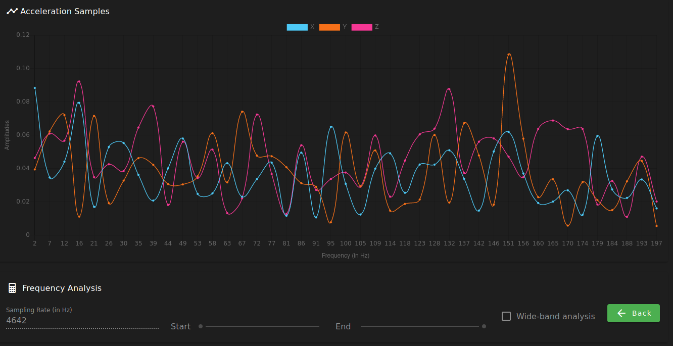
Replaced the sleeve cable with a cat5e ethernet one and now it works.
Graph is all over the place but it works.

Replaced the sleeve cable with a cat5e ethernet one and now it works.
Graph is all over the place but it works.

Replaced the sleeve cable with a cat5e ethernet one and now it works.
Graph is all over the place but it works.

@phaedrux I'll try that but the current cable length is just long enough for operation. I'll test with a cat5e ethernet cable.
I have connected my accelerometer board successfully but can't get a reading from it.
RRF Version: 3.4.1
Boards: Duet2 Wifi, Duex5
Accelerometer: type LIS3DSH 16-bit resolution, SPI frequency 2000000
Configured it with
M955 P0 C"duex.cs6+spi.cs4" M955 P0

# Console:
M955 P0 C"duex.cs6+spi.cs4" M955 P0
Accelerometer 0 type LIS3DSH with orientation 6 samples at 1600Hz with 16-bit resolution, SPI frequency 2000000
Issue #1: Can't get readings from accelerometer
Connected the CS with a separate wire to duex.cs6 to avoid interference. But when I tried testing it with:
G90 G1 X130 G1 X180 G4 S2 M956 P0 S1000 A0 G4 P10 G1 X130 F20000
The resulting CSV is written as:
Sample,X,Y,Z
Failed to collect data from accelerometer
Then I tried changing it's configuration to the recommended 10 bit resolution, 1344Hz sampling rate, which led me to the second issue...
Issue #2: The M955 R and S parameters are ignored
M955 P0 C"duex.cs6+spi.cs4" I06 S1344 R10 M955 P0

# Console:
# Ignores the S and R new settings
M955 P0 C"duex.cs6+spi.cs4" I06 S1344 R10 M955 P0
Accelerometer 0 type LIS3DSH with orientation 6 samples at 1600Hz with 16-bit resolution, SPI frequency 2000000
Then I tried changing the Q parameter and it's accepted:
M955 P0 C"duex.cs6+spi.cs4" I06 S1344 Q1000000 M955 P0

# Console:
M955 P0 C"duex.cs6+spi.cs4" I06 S1344 Q1000000 M955 P0
Accelerometer 0 type LIS3DSH with orientation 6 samples at 1600Hz with 16-bit resolution, SPI frequency 1000000
I've already checked every connector for signal continuity and every pin source/destination twice. The cable 2m long sleeve with 10 cables in it.
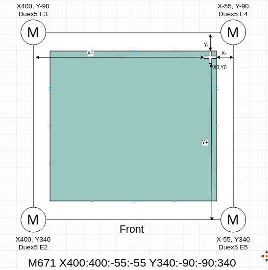
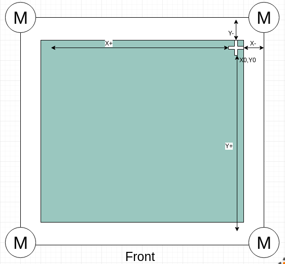
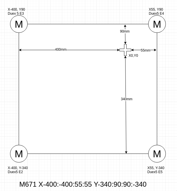
Then, the right motors' coordinates should be:

@Danal These are my printer coordinates. I have defined the M671 coords based on the X0,Y0 point. Now I see what I've got wrong about the signals.

@Danal Like this? The distance was measured according to your description about the pivot point (in my case the center of the belts)
The resulting gcode is at the bottom, considering the sequence that the motors are connected to the Duex5

I'm adjusting the M671 command for my Voron 2.1 printer and I just can't figure out what's the reference point for the motor's positions.
Is it the nozzle at Z0? Is it the nozzle at homed position of the gantry (which, in my case, it's a negative value being the 0,0 the back right corner)?
I've replaced the U2 voltage regulator of my Duet2 board but the component is still outputting 0.3v and works fine using an Arduino on the 3.3v rail, as recommended.
How can I diagnose the C4 capacitor of the 3.3v regulation system?
@bearer Yeah, I have a presentation to write right now but I'll do a full test, connecting the board to my Voron. If the processor is alive, it's a great thing already. I'll start replacing U2 (no pun intended).