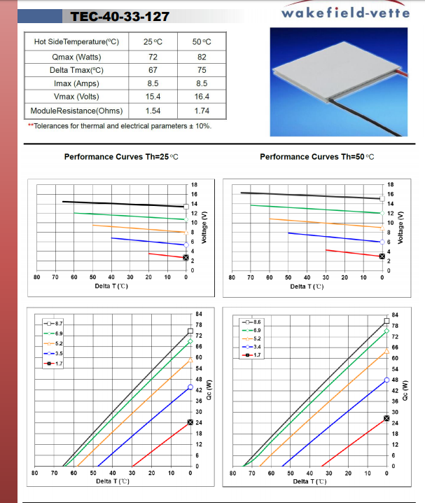
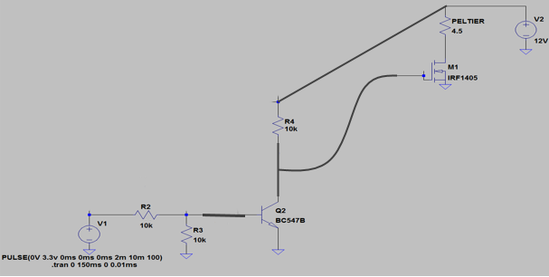
I forgot to mention, my peltier is TEC-40-33-127. I apply at the PWM input 3.3V and i think my circuit is not ok because the launchpad (MSP430FR4133) "scream".
Latest posts made by Dani111
-
RE: Circuit-design Peltier Elementposted in Duet Hardware and wiring
-
RE: Circuit-design Peltier Elementposted in Duet Hardware and wiring
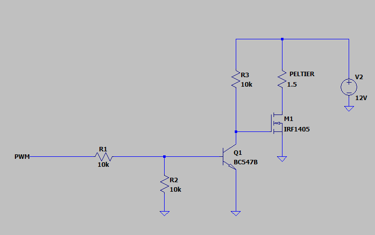
I'm using this schematic, but it's not okay. I'm not sure which series of transistors to choose and i need help for that

-
Circuit-design Peltier Elementposted in Duet Hardware and wiring
Hi. I need a little help from experienced people.
I want to control a Peltier element with a microcontroller,
with PWM. May? The peltier element has the following parameters:
Imax=8.5 A, Vmax=15.4V.Ok... I have a 12 volt source,17A for example.How can i design the circuit so that i can control the peltier element?
A link to the peltier element data sheet is:
https://eu.mouser.com/datasheet/2/433/Wakefield_Vette_Thermoelectric_Cooler_Full_Data_Sh-1501217.pdf -
Peltier Element- Schematic Help H-bridgeposted in Duet Hardware and wiring
Hello,
I need help to anyone who can help me
A peltier can be reversed. So If I supply + to RED and - to BLACK
it works as expected. But if I reverse the polarity, ( - to RED, + to BLACK), it will also reverse the cold and hot side.
(To prevent the other side getting too hot, I have a heatsink on it with a fan blowing cool air over it.)
I want to connect and control the element using MSP430 as launchpad(power supply: 3.3v) I use TEC-40-33-127.
I need to think about how to connect and control the 4 switches (4x IRF1405) to power the peltier in both ways, how to use the H-Bridge in both polarities.
I need your help because I don't know how to make the circuit schematic I don't know what values to choose from resistors,
capacitors and what kind of diodes to use, how to to maintain the current so as to the whole circuit should work .
I attached below an exemple without H-bridge and I want something similar as in the schematic but for my element and with H-bridge.

Thank you!