Duet3D Logo Duet3D
    • Tags
    • Documentation
    • Order
    • Register
    • Login
    1. Home
    2. Larzarus
    • Profile
    • Following 0
    • Followers 0
    • Topics 1
    • Posts 10
    • Best 3
    • Controversial 0
    • Groups 0

    Larzarus

    @Larzarus

    5
    Reputation
    1
    Profile views
    10
    Posts
    0
    Followers
    0
    Following
    Joined Last Online
    Location California

    Larzarus Unfollow Follow

    Best posts made by Larzarus

    • RE: 6th-order jerk-controlled motion planning

      So, FWIW, I'll throw in my two cents. Three years ago I did some experiments with implementing s-curve / sinusoidal jerk in a Marlin based firmware (UM2) (I used a lookup table instead of calculating it). Let's see how much I remember...

      I found it did not really improve print quality, at least not in any way I could see with the naked eye. But it did allow for faster usable movement without shaking the machine or wild oscillations. Especially non-printing moves, as my printer is mostly limited in printing speed by the extruder design. I was printing with good quality at 120mm/s, infill at 250mm/s, and non-printing moves in the 450-550mm/s range. Those are max speeds, but net average speed was within 80-90% of the max speed (depending on segment length mostly). I put up some videos (and a link to the code) here: https://www.youtube.com/watch?v=D9tGB-FtyJQ and a high speed non-printing movement / wobble test here https://www.youtube.com/watch?v=-L8scUiasVg (without S-curve, it was much more violent and that pen would fall over at less than half the max speed)

      The main benefit of s-curves was I could use much much higher acceleration values. In theory I could get to those same speeds without s-curve, but I would have to keep the acceleration values low to prevent the machine shaking itself apart when it changed direction... but a high max speed with low acceleration doesn't help because the head would only reach those speeds on very long movement segments. The improvement to acceleration is what made those speeds achievable / beneficial, even on shorter movement segments.

      550mm/s was pretty much the upper limit of my machine's design (belts, motor current, the rate at which the CPU could generate pulses, etc). Even then I had to make some dynamics optimizations to the Marlin movement stepper pulse generator code to move at that speed. But it would very very rarely skip steps. Like maybe once every couple hours; enough to mess up a print (it was an issue with the i2c comm interrupt blocking the stepper movement interrupts). Ultimately I think it came down to pushing hard against the limits of that 8 bit CPU. If I limited the speed to under 300mm/s, it was pretty rock solid.

      I gave up on further code development when I switched to the Duet Wifi from the AVR based UM2 motherboard. 😉

      It's been three years since I did this code, so I've forgotten many of the implementation details, and I do not have the desire to debate. I am relaying my personal experience implementing this on a real world printer, with real world testing. I found the s-curve was well worthwhile in reducing oscillations, violence, noise, etc. and far less computational taxing than true 5-6th order calculations. I agree it should be optional.

      I'll add that since I switched the the Duet and no longer use s-curve motion, I don't really miss it that much. Yes, it allowed faster net printing, but I'm still extruder-limited most of the time anyway.
      posted in Firmware wishlist
      Larzarusundefined
      Larzarus
    • RE: 6th-order jerk-controlled motion planning

      @carlosspr Take a look at this article: https://pdfs.semanticscholar.org/6539/02c3dbd1aa7afe4d5f3538524de149d4ecb2.pdf It explains how to achieve the desired 0 jerk / 0 accel at the crossover points. It's also got some empirical data on resulting forces and movement execution time, showing the benefit in quantifiable terms. It's worth the read.

      posted in Firmware wishlist
      Larzarusundefined
      Larzarus
    • RE: 6th-order jerk-controlled motion planning

      @dc42 said in 6th-order jerk-controlled motion planning:
      ...

      So at present I favour traditional S-curve motion (3rd order motion profile). See https://pdfs.semanticscholar.org/a229/fdba63d8d68abd09f70604d56cc07ee50f7d.pdf. But before I make a decision, is anyone reading this thread aware of any evidence that higher order motion profiles are advantageous?

      @dc42 I'm gonna throw in this quote from the paper I linked to:

      ...the trigonometric S-curve trajectory is:
      • simple as 3rd order polynomial model and
      • capable of producing smooth trajectory as good as 5th order polynomial S-curves and quintic splines

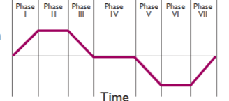
      That's what drew me to this solution in my testing -- a close approximation of 5th order with only 3rd order effort, by replacing this angular jerk curve:

      0_1524258811822_e98cd887-dc4d-42fa-9a1c-12e20151f07a-image.png

      with a sinusoidal jerk curve -- I mean look at it, it's beggin' for it! 🙂 If you're considering limiting the implementation to 3rd order to keep it simple / maintain performance, this may be something easy and worth adding?

      Honestly, anything that get us away from instantaneous jerk is going to be the largest single improvement (even the simplest 3rd order will help).

      Beyond that, the debate over what's the best way to shape higher orders (splines, trig, polynomials, etc) can go on forever, and no answer will please everyone. I don't know how reasonable it is, as this is deeply tied into everything motion planning, but maybe consider if it's possible to encapsulate that shaping math enough that others can plug in their favorite method? You know, to get people off your back. 🙂

      posted in Firmware wishlist
      Larzarusundefined
      Larzarus

    Latest posts made by Larzarus

    • RE: 6th-order jerk-controlled motion planning

      @dc42 Zero acceleration at the end points is shown in many examples, but it is not a requirement of this approach. Jerk is zero at the end points (a good thing) but acceleration at the start and end of the segment can be any value.

      The sinusoid function is applied to jerk, which will result in a graceful s-curve acc instead of an angular one. You can still calculate all seven phases separately, with the sine function only being applied to jerk when jerk !=0. The only difference to the normal 3rd order calculation is instead of calculating linear jerk (a = a + j *t) for phases I, III, V, and VII, you apply the sine scalar multiplier (half sine wave on each phase) to the j term. Phases II, IV, and VI stay linear (jerk = 0) and be as long or short as necessary.

      Yes, sine is a lookup table (one quarter cycle is enough, as you can flip it and/or invert to get the entire curve as needed)

      posted in Firmware wishlist
      Larzarusundefined
      Larzarus
    • RE: 6th-order jerk-controlled motion planning

      @dc42 said in 6th-order jerk-controlled motion planning:
      ...

      So at present I favour traditional S-curve motion (3rd order motion profile). See https://pdfs.semanticscholar.org/a229/fdba63d8d68abd09f70604d56cc07ee50f7d.pdf. But before I make a decision, is anyone reading this thread aware of any evidence that higher order motion profiles are advantageous?

      @dc42 I'm gonna throw in this quote from the paper I linked to:

      ...the trigonometric S-curve trajectory is:
      • simple as 3rd order polynomial model and
      • capable of producing smooth trajectory as good as 5th order polynomial S-curves and quintic splines

      That's what drew me to this solution in my testing -- a close approximation of 5th order with only 3rd order effort, by replacing this angular jerk curve:

      0_1524258811822_e98cd887-dc4d-42fa-9a1c-12e20151f07a-image.png

      with a sinusoidal jerk curve -- I mean look at it, it's beggin' for it! 🙂 If you're considering limiting the implementation to 3rd order to keep it simple / maintain performance, this may be something easy and worth adding?

      Honestly, anything that get us away from instantaneous jerk is going to be the largest single improvement (even the simplest 3rd order will help).

      Beyond that, the debate over what's the best way to shape higher orders (splines, trig, polynomials, etc) can go on forever, and no answer will please everyone. I don't know how reasonable it is, as this is deeply tied into everything motion planning, but maybe consider if it's possible to encapsulate that shaping math enough that others can plug in their favorite method? You know, to get people off your back. 🙂

      posted in Firmware wishlist
      Larzarusundefined
      Larzarus
    • RE: 6th-order jerk-controlled motion planning

      @carlosspr Take a look at this article: https://pdfs.semanticscholar.org/6539/02c3dbd1aa7afe4d5f3538524de149d4ecb2.pdf It explains how to achieve the desired 0 jerk / 0 accel at the crossover points. It's also got some empirical data on resulting forces and movement execution time, showing the benefit in quantifiable terms. It's worth the read.

      posted in Firmware wishlist
      Larzarusundefined
      Larzarus
    • RE: 6th-order jerk-controlled motion planning

      I've got mixed feelings about the benefit for normal use. I was doing experiments to push the limits of my machine. If you routinely run your machines close to its limits (extruder, mechanical, etc), then yes, definitely worthwhile and 'something for nothing' (except programmer effort!). I used it daily for well over a year with good results, squeezing some extra performance from my rig. Switching to the DuetWifi, I dialed back the speed and accel, but for daily use I don't really I miss it much. Would I use it if it was there? Sure. But it's a fringe nice to have, not a core requirement.

      In terms of nitty gritties, I kept the 'phases' the same in the Marlin motion planner -- the 3 phase trapezoid of accel, coast, dec. To implement the sinusoidal jerk, I injected some code into the pulse generator loop, where the accel phase had a function of speed = speed + accel (similarly speed = speed - accel for dec phase). I replaced the accel term with a fixed-point math lookup table of a pre-generated sine curve** (multiplied by accel). The table has an almost-linear section in the middle, effectively making for three blended sub-phases (net 7 motion planner phases, as dc42 is refers to).

      This shaped the accel and dec sections of the trapezoid into the desired s-curve. I wouldn't say it's proper by any means, but it was achievable on the 8 bit cpu in terms of performance and without an entire rewrite of the motion planning codebase. A quick hack, enough to test if s-curves provided any benefit...It did result in smoother movement (less violence / oscillation and quieter), allowing me to increase acceleration, which increased net average speed per segment.

      I'm sure dc42 has a very clear picture of what would be needed to implement it: certainly a more correct, complicated and involved effort than my tests. There is a definite benefit, for some, but is it worth the effort? Dunno.


      ** taking care that my pre-generated curve maintained the same 'area under the curve' integral as the instantaneous jerk / line accel would, so the resulting phase resulted in the same total number of movement steps (at least to the limits of the fixed point math the wimpy 8 bit cpu is capable of)

      posted in Firmware wishlist
      Larzarusundefined
      Larzarus
    • RE: 6th-order jerk-controlled motion planning

      So, FWIW, I'll throw in my two cents. Three years ago I did some experiments with implementing s-curve / sinusoidal jerk in a Marlin based firmware (UM2) (I used a lookup table instead of calculating it). Let's see how much I remember...

      I found it did not really improve print quality, at least not in any way I could see with the naked eye. But it did allow for faster usable movement without shaking the machine or wild oscillations. Especially non-printing moves, as my printer is mostly limited in printing speed by the extruder design. I was printing with good quality at 120mm/s, infill at 250mm/s, and non-printing moves in the 450-550mm/s range. Those are max speeds, but net average speed was within 80-90% of the max speed (depending on segment length mostly). I put up some videos (and a link to the code) here: https://www.youtube.com/watch?v=D9tGB-FtyJQ and a high speed non-printing movement / wobble test here https://www.youtube.com/watch?v=-L8scUiasVg (without S-curve, it was much more violent and that pen would fall over at less than half the max speed)

      The main benefit of s-curves was I could use much much higher acceleration values. In theory I could get to those same speeds without s-curve, but I would have to keep the acceleration values low to prevent the machine shaking itself apart when it changed direction... but a high max speed with low acceleration doesn't help because the head would only reach those speeds on very long movement segments. The improvement to acceleration is what made those speeds achievable / beneficial, even on shorter movement segments.

      550mm/s was pretty much the upper limit of my machine's design (belts, motor current, the rate at which the CPU could generate pulses, etc). Even then I had to make some dynamics optimizations to the Marlin movement stepper pulse generator code to move at that speed. But it would very very rarely skip steps. Like maybe once every couple hours; enough to mess up a print (it was an issue with the i2c comm interrupt blocking the stepper movement interrupts). Ultimately I think it came down to pushing hard against the limits of that 8 bit CPU. If I limited the speed to under 300mm/s, it was pretty rock solid.

      I gave up on further code development when I switched to the Duet Wifi from the AVR based UM2 motherboard. 😉

      It's been three years since I did this code, so I've forgotten many of the implementation details, and I do not have the desire to debate. I am relaying my personal experience implementing this on a real world printer, with real world testing. I found the s-curve was well worthwhile in reducing oscillations, violence, noise, etc. and far less computational taxing than true 5-6th order calculations. I agree it should be optional.

      I'll add that since I switched the the Duet and no longer use s-curve motion, I don't really miss it that much. Yes, it allowed faster net printing, but I'm still extruder-limited most of the time anyway.

      posted in Firmware wishlist
      Larzarusundefined
      Larzarus
    • RE: G10/G11 hardware retraction changed in 1.19b5?

      Good to know I'm not completely crazy. 🙂 (Maybe just partially… )

      I'll look into what I'm doing wrong with the feedrate. Thanks!

      posted in Tuning and tweaking
      Larzarusundefined
      Larzarus
    • G10/G11 hardware retraction changed in 1.19b5?

      I upgraded from 1.18 to 1.19b5 today and while it seems to be a successful upgrade, I am finding G10/G11 hardware retraction is not working like it did before. It appears as if it's running at maximum extruder speed (3000) instead of the feedrate specified by M207 (800) and it also appears to be only moving forward (ie: both G10 and G11 advance the filament). Since it's max extruder speed, it just chews up the filament (or thunks the extruder motor) instead of actually feeding filament. Normal extraction moves are OK. Doing manual g-code retract and unretract works OK.

      I've got M207 set to[c] Retraction/un-retraction settings: length 1.50/1.50mm, speed 800/800mm/min, Z hop 0.00mm[/c]

      and my movement config is set to:

      [[language]]
      M566 X900 Y900 Z24 E240 ; Set maximum instantaneous speed changes (mm/min)
      M203 X12000 Y12000 Z2500 E3000 ; Set maximum speeds (mm/min)
      M201 X2000 Y2000 Z050 E1500 ; Set accelerations (mm/s^2)
      
      ```and a sample piece of g-code using G10/G11:
      

      [[language]]
      G10
      G92 E-4.00000
      G1 X112.350 Y93.686 Z0.250 F3600
      ;TYPE:SKIRT
      G11
      G92 E0.00000
      G1 X112.965 Y93.053 E0.01868 F2700
      G1 X113.634 Y92.477 E0.03736
      G1 X114.353 Y91.964 E0.05605

      These G10/G11 commands have been working properly for me in Marlin, RepRap, previous Duet releases, etc. Did anything change in regards to G10/G11/M207 behavior? Any clues what's going on? Really odd….
      posted in Tuning and tweaking
      Larzarusundefined
      Larzarus
    • RE: Firmware 1.18 released

      @dc42:

      The usual reason for the extruder moving incorrectly during printing is mixing up relative and absolute extruder coordinates. If you use relative extruder coordinates, make sure you include M83 in your start gcode. If you use absolute coordinates, make sure you have M82 in your start gcode.

      Yes, that was it, thanks. I use absolute extruder positioning in my gcode files, but I've got some relative extruder moves for retraction / priming in the config files resume.g, pause.g, etc. Never had an issue with 1.17rc3 but maybe something changed with when those files are called? Everything is working fine now by adding an explicit M82 in the header of the gcode.

      posted in Firmware installation
      Larzarusundefined
      Larzarus
    • RE: Solidoodle? and K40 laser cutter

      Straight from China, K40s usually use old bootleg CorelDraw with a special plug in (sometimes requiring a hardware dongle), or "Moshidraw" – which is pretty much universally despised. Either option is crap, unstable, difficult to use, closed source, proprietary protocols, etc. Plus the controller hardware is usually dubious.

      Getting rid of the provided electronics and putting in a RAMPS / Smoothieboard / GRBL / Marlin / or anything-but-the-crap-it-came-with is one of the higher priority upgrades in terms of usability. It would be nice to have Duet on that list of choices. My K40 is ripped apart undergoing this process (planning on using my spare Smoothieboard for it)

      Once the controller is changed out, Laserweb is one of the better choices for cutting and raster control. Open source, cross platform, g-code based, under active development, good wiki, etc. https://github.com/LaserWeb/LaserWeb3 It plays nicely with Smoothieware in particular because of some of the additional laser power control features in it, like integrating the power level with the acceleration curves (something not possble with RAMPS / Grbl). Adding that into Duet would bring it on par with Smoothieware for laser cutting. I'd start there to see what needs to be added for full laser cutter / rastering support.

      Some older K40s use an analog pot / voltage for laser power control, with no direct way for the controller to vary the power. More recent ones have a different power supply design which runs PWM (I think 20Khz ?) to control power. There's also a separate laser fire contact closure to ground trigger. Some people set their controller to PWM the trigger to adjust laser power, other configurations maintain separate trigger and power control signals. (there's also a laser enable input, which is usually wired to a toggle switch on the control panel.).

      The laser has a minimum value for the laser to fire, usually around 20-25% power level, which is another thing that needs to be considered when implementing the PWM control.

      I'm not fond of the cabling that came with my K40, so having a drop in replacement that uses the same cables isn't a bonus for me. I am not sure all the variations and evolution of the K40 all use the same cabling – they are at least three different controller boards, with several revisions of each, out in the wild. But at the very least, the flat ribbon cable used to drive one of steppers and end stops is inadequate, fragile and does not stay connected well during high speed moves.

      With a new controller you're probably also going to want to add some cabling for some of the common upgrades: another axis for a z-lift bed or rotational axis, cooling water temperature and flow monitoring, toggles for case lighting, targeting laser(s), air assist, exhaust ventilation, water pump, etc. It would be nice to be able to have those integrated with Duet through the unused GPIO / mosfets (probably most of it can be done with existing config options).

      K40s don't come with any sort of safety interlocks, which is insanely risky, so that's also something to consider adding (although they can be added inline with the laser enable switch for a purely hardware solution).

      One final thought: make sure to really triple check the grounding before firing up a K40. The laser's ground return path is through the ammeter in the control panel (!) and then to ground (which is also tied to chassis ground). If that ground path ever disconnects, there's the potential for 20+KV to be floating around in the control panel / metal frame. Yikes. I was uncomfortable with that so I added a separate isolated current meter and safety spark-gap -- which I'd like to hook into the controller eventually via an analog input so I could close the feedback loop on the laser power control.

      posted in My Duet controlled machine
      Larzarusundefined
      Larzarus
    • RE: Firmware 1.18 released

      Uh… So something weird is going on for me. I had been running 1.17rc3 for a couple months without issue. Updated for 1.18 yesterday (along with making a few other wiring changes to my fans) along with the 1.15a web interface and the web server to 1.03ch. Everything seemed great until I printed. My extruder was moving WAY WAY WAY too fast. I tried different gcode files, changing the steps per mm, microstepping, etc. and it is just crazy fast. The other axis are OK. I went back to 1.17rc3 and it's working fine again (left the server and web insterface at latest). I can't imagine this is happening to everyone, it's pretty obvious show stopper. But I'm baffled as to why it's happening to only the extruder and only with 1.18.

      Here is my config.g section for the motors:

      [[language]]
      ; Drives
      M569 P0 S1 ; Drive 0 goes forwards
      M569 P1 S0 ; Drive 1 goes backwards
      M569 P2 S1 ; Drive 2 goes forwards
      M569 P3 S0 ; Drive 3 goes backwards
      M350 X16 Y16 Z16 E16 I1 ; Configure microstepping with interpolation
      M92 X80 Y80 Z400 E152 ; Set steps per mm
      M566 X900 Y900 Z24 E240 ; Set maximum instantaneous speed changes (mm/min)
      M203 X15000 Y15000 Z2500 E3000 ; Set maximum speeds (mm/min)
      M201 X2500 Y2500 Z050 E5000 ; Set accelerations (mm/s^2)
      M906 X1300 Y1300 Z1100 E1800 I20 ; Set motor currents (mA) and motor idle factor in per cent
      M84 S30 ; Set idle timeout


      Any ideas?

      Thanks
      Lars

      posted in Firmware installation
      Larzarusundefined
      Larzarus