Duet3D Logo Duet3D
    • Tags
    • Documentation
    • Order
    • Register
    • Login
    1. Home
    2. carlosspr
    • Profile
    • Following 0
    • Followers 0
    • Topics 3
    • Posts 57
    • Best 10
    • Controversial 0
    • Groups 0

    carlosspr

    @carlosspr

    13
    Reputation
    4
    Profile views
    57
    Posts
    0
    Followers
    0
    Following
    Joined Last Online

    carlosspr Unfollow Follow

    Best posts made by carlosspr

    • RE: 6th-order jerk-controlled motion planning

      Hi, I am trying to do some progress with this. Las post from Lazarus was very clarifying and opened some ideas that I have been exploring. I would like to share with the forum the process to add some light to the maths behind the algorithm so that I can get closer to an implementation.

      The first thing that called my attention from Lazarus' last post was the use of sinusoidal functions to generate an S-Curve. It triggered a lot of crazy ideas to use signal processing algorithms to work on the frequency domain, so I crushed the numbers. Unfortunately the sinusoidal waveforms do not meet the requirements.

      Which are the requirements that the ideal S-Curve shall meet?:

      • It shall have acceleration=0 (dv/dt =0) at the joints of the trapezoid.
      • lt shall have jerk =0 at the joints of the trapezoid (dv/dt2 =0 ).
      • It shall fit on the control points to the trapezoid acceleration and deceleration phases.

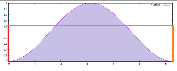
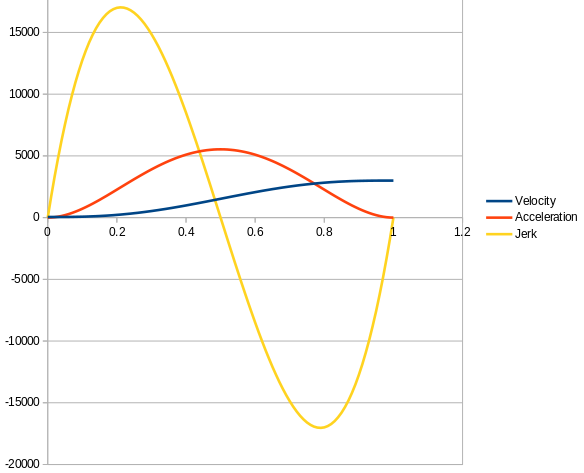
      Sinusoidal waveforms can fit the trapezoid and have zero acceleration on the joints, but will fail on jerk. The maths behind this: If we use sin(t) to generate the shape, its derivative cos(t) will start and stop at 0, but its second derivative -sin(t) will not. the following graph shows an example on a Spreadsheet of Velocity, Acceleration and Jerk using sinusoidal waveforms where jerk is celarly non-zero on the trapezoidal joints:
      0_1524155388661_Velocity-Accel-jerk_with_sinusoids.png

      Sadly I had to abandon the idea to use sinusoidal waves and started looking at the Bezier curves, but realized that not all Bezier curves could be fit to meet the requirements and at least a fifth order Bezier curve is required is we want to assure jerk=0 and higher orders would ensure also snap crack or pop. Since Bezier curves can be derived to infinite, it is a matter of increasing the order. However the mathematical complexity is probably not worth to compensate some effects that are physically hard to understand (I see them as harmonics of low effect). With a fifth order Bezier we can express the velocity in function of time with the following formula:

      • V(t) = At^5 + Bt^4 + Ct^3 + Dt^2 + E*t + F

      Where t is normalized time (from 0 to 1). And the challenge is to solve the weights (A,B,C,D,E,F). For this we apply the constraints

      • Constraint #1: dv/dt =0 at t=0 produces the first solution E=0.

      • Constraint #2: dv/dt2 =0 at t=0 produces the second solution D=0
        So having E0= and D=0 warrants a jerk-free curve on the joints.

      • Constraint #3: fit the curve to start speed and top speed.

      • Constraint #4,5: force dv/dt=0 and dv/dt2=0 at t=1 produce other equiations that combined will solve to the final result.

          A = -6*initialSpeed +  6*endSpeed
          B =  15*initialSpeed - 15*endSpeed
          C = -10*initialSpeed + 10*endSpeed
          D = 0
          E = 0
          F = initialSpeed
        

      On the Acceleration Phase
      initialSpeed=startSpeed
      endSpeed=topSpeed

      On the decceleration phase
      initialSpeed=topSpeed
      endSpeed=stopSpeed

      The same formula applies, but if startSpeed is different that stopSpeed, the coefficients need to be recalculated to fit the trapezoid properly.

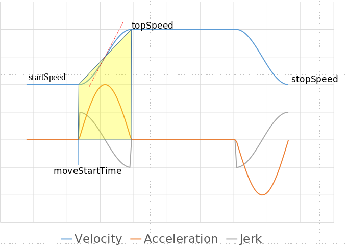
      The following graph shows the graphical representation of the S Curve, acceleration and jerk using the brute force calculation on a Spreadsheet of the formula (i used startSpeed=50 and topSpeed=3000):
      0_1524156429000_Bezier-velocity-accel-jerk.png

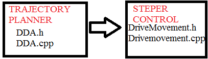
      So these are the maths and are not so complex once understood. Now the challenge is the implementation. For that I have been reading the implementation of Movement in ReprapFirmware (and I will have to read another dozen times before I get comfortable with it and attempt to do any attempt to modify anything), so far, what I have understood is the following (and the experts can correct me if I misunderstood the code):

      DDA.cpp deals with the motion planning.
      DDA::Init(): would require a call to a function that calculates the coefficients of the S-Curve (A,B,C,F) each time there is a new value for "Startspeed","topSpeed" or "endSpeed".

      DriveMovement.cpp
      DriveMovement::CalcNextStepTime() contains the loop that define the frequency of calls to the ISR interrupts in nextCalcStepTime.
      This is defined as follows for a cartesian printer:

      // acceleration phase
      const uint32_t adjustedStartSpeedTimesCdivA = dda.startSpeedTimesCdivA + mp.cart.compensationClocks;
      nextCalcStepTime = isqrt64(isquare64(adjustedStartSpeedTimesCdivA) + (mp.cart.twoCsquaredTimesMmPerStepDivA * nextCalcStep)) - adjustedStartSpeedTimesCdivA;

      I am still having trouble to understand this (it is a big challenge for me!), but looks like it is calculated as a function of A (meaning Acceleration?). If this is the case, it would be a matter of adding an "if (trajectoryPlanning=bezier) { nextCalcStepTime = a_function_of_the_variable_S_Curve_velocity_in_realtime}.

      [the if... would allow to define an M code and make the feature configurable]

      Another "major" challenge to reach the goal is too find a method to calculate v(t) [or (a(t)] in an efficient manner for a real-time system.
      TinyG is using "Forward Difference Calculation" algorithm. Forward differencing is an efficient scheme for evaluating a polynomial at many uniform steps, but it will not work if the steps are not uniform.
      Marlin is tickless, i.e., interrupts are only generated where a step (or some other event) has to be scheduled. Because of this Marlin implementation could not use TinyG approach and their solution consisted to transform the math to use fixed point values to be able to evaluate it in realtime and they implemented this portion in assembler code to be even more efficient.

      In the case of Duet, I need to read further, but would appear that it is also tickless. We might explore other algorithms (probably we could not do better than Horner's method) or adopt Marlin's approach.

      It's been a long post, but I would hope that it is useful and leads us to a successful implementation of a new feature that is already receiving lots of recognition by the Marlin community.

      Carlos.

      posted in Firmware wishlist
      carlossprundefined
      carlosspr
    • RE: Auto tune cancelled because target temperature was not reached

      I understand you are triying to auto tune the PID. Which P value are you using for M301 command?. Try increasing it to ramp up the heating curve, until you get a good result without overshoot warnings.

      posted in General Discussion
      carlossprundefined
      carlosspr
    • RE: Fans and stuff improvements…

      I would also vote for this.

      I would like to check the status of the fans. For example, when I turn on the printer, I would like to check if all the sensors/fans are connected and ready to be read or not. Maybe one fan is unplugged and I want to detect this situation.

      In the case that the fan dies, this feature would avoid a failed print or blocked nozzle.

      posted in Hardware wishlist
      carlossprundefined
      carlosspr
    • RE: 6th-order jerk-controlled motion planning

      +1 to S-Curve implementation. This video is the perfect demonstration for an enhanced quality (noticeably less ringing in the print). https://www.youtube.com/watch?v=C0XjXqO6Ji8

      I have been looking at the implementation of the S-Curve motion control in Marlin and TinyG. It oly works on 32bit CPUs as AVR simply does not have enough processing power for this.
      TinyG implementation is well explained nd has references to some papers with the maths behind the code: (https://github.com/synthetos/TinyG/blob/master/firmware/tinyg/plan_exec.c#L243).

      They're using 5th-order Bezier velocity curves to get 6th-order position planning. When planning each velocity change, the math assumes that acceleration and jerk start at zero, which allows to significantly simplify the math.

      Note that both solutions are still using trapezoids to drive overall velocity changes, it's just that the velocity changes are smoothed using the 5th-order Bezier curves.

      The logic is also very clearly explained at https://github.com/MarlinFirmware/Marlin/pull/10337.

      ejtagle opened this pull request in MarlinFirmware/Marlin

      closed [2.0.x] 6th-order jerk-controlled motion planning in real-time #10337

      posted in Firmware wishlist
      carlossprundefined
      carlosspr
    • RE: Motor stall detection as Z probe

      I have tested the feature on 2.0(RTOS)beta2 and it works.
      I have a Cartesian printer with dual Z axis connected in Serial. The problem is that the Force of the nozzle when it hits the bed overshoots a little bit the bed due to the springs and that makes unfeasible for mesh bed leveling.

      However, an excellent finding is that G30 executed on the same X,Y coordinates gives exactly the same result. As a test I run G30 S-1 20 times and I got the same result all 20 times on the same spot with 0 standard deviation!. I think that the overshoot is to the next "full step" and this is allowing a very good accuracy.

      Basically is an excellent Z-min switch that does not require calibration and takes into account thermal expansions.

      I have made a small script to use Z stall before G30 and change back to NPN capacitive probe for bed leveling. The results are excellent, I do not have to worry about the Z offset of the probe because it is only used to level a plane and the repeat ability of the Stall always on the same spot is extremely repetitive. First layer always perfect.

      My script in case that someone is interested.

        ;find_zero_and_level.g
        G90                ;absolute positioning
        G1  X110 Y105 Z10 F4000 ; Always probe on the same spot
        M558 P10 X0 Y0 Z0 H2 F600 T5000	    ; Enable Stall Z probe
        G31 X0 Y0 Z-0.77 P200           ; Set Z probe trigger value, offset and trigger offset (overshoot due to springs)
        M574 Z1 S3         	    	; set Z-min to use motor StallGuard
        M913 Z20   		      	; reduce motor current to 20%
        M201 Z30			; Reduce acceleration mm/s2
        M915 Z S-2.9 F0 R0		; Set StallGuard sensitivity for endstop homing
        G30; Find the bed Z=0 reference
        G1 Z2
        G30 S-1 ; do a couple of repeteability tests
        G1 Z2
        G30 S-1 ;
        G1 Z2
        G30 S-1 ;
        G1 Z2
        G30 S-1 ;
        M913 X100   		      	; restore current to 100%
        M201 Z300 			; Restore acceleration
      
        ; Revert back to Capacitive Z probe NPN
        M558 P4 X0 Y0 Z0 H3 I1 F300 T5000	  
        G31 X23.5 Y5 Z1.04 P200           ; Set Z probe trigger value, offset and trigger height.
        G29 S2  	; Clear any bed leveling compensation
        G29 S0 			 ; Run probing sequence defined by M557 on the config.g
        M374 			 ; Save calibration data in sys/heightmap.csv
      

      I have added M98 P/sys/find_zero_and_level.g on the start G-Code script on the slicer and the results are more than satisfactory for me.

      posted in Tuning and tweaking
      carlossprundefined
      carlosspr
    • RE: [Solved] Stall detection for homing issue

      Stall detection is tricky, but I have got it working nicely and I am very happy with it. With 12V I could home X and Y on a Cartesian, but noz Z. After I switched to 24 V I could home all three axis with Stall.

      On you configuration file

      M915 X S5 F1 H200 R0				; set stall detection for X axis
      

      Modify/disable the Filter Mode (Replace F1 by F0) . According to Trinamic:

      SFILT=O The filtering is disabled and a change of load is detected within a quarter electrical period that is one full step.
      SFILT=1 The filtering is enabled and a change of load is detected within an electrical period. For higher dynamic change of load the SFILT needs to be switched off.

      Stall depends on the motor parameters, supply voltage, speed, current, and amount of mechanical load. Some additional tuning that you might want to do:

      • The stallGuard trigger value depends on the amplitude of the motor current linked to the supply voltage. Try to further reduce the current and see if you get better results. If the current is too low you will get quick False stalls, from that point increase slowly until the false stalls dissapear.
      • The trigger value varies with the velocity because it bases on the Back-EMF of the stepper motor. You want to hit the endstop at some speed, but with good dynamic margin. Just enough to break the back-EMF is the mest settings that I have found as they allow for lower trigger values (higher sensitivity). Try reducing the speed a little (3000 mm/min) and check again.
      posted in General Discussion
      carlossprundefined
      carlosspr
    • RE: 6th-order jerk-controlled motion planning

      @deckingman said in 6th-order jerk-controlled motion planning:

      What concerns me now is that a new motion system may not be something that I could choose to use or not.

      Agreed. A new motion planner should not be a replacement, but rather an option. But there is no reason to deny the feature that according the marlin posts is showing a big impact on printer vibrations.
      There are many algorithms for motion planning in the technical literature and a proper software architecture would allow to select which planner to use. Marlin team has solved this issue with a compilation directive that you can define or not in Configuration.h when you prepare your firmware letting you the option to use it or not.

      posted in Firmware wishlist
      carlossprundefined
      carlosspr
    • RE: 6th-order jerk-controlled motion planning

      @larzarus yours is a very interesting experience, which suggests me that there is still invaluable desirable effects on this S-Curve implementation. Beyond printing speeds, the hardware in the printers will be less exposed to wear and tear and the expected hardware life will increase. Also maintenance cycles will be lower. With less vibrations bolts will not become loose and steppers will not have to absorb the vibrations.

      I have read the Movement code and it seems that DriveMovement.cpp also uses a trapezoid. There are references on the code to an "Acceleration phase", " Constant speed phase" and "Deceleration phase". In an analogy with TinyG implementation, they make a sub-division of the same trapezoid into 5 segments: First and second halves of the acceleration ramp (the concave and convex parts of the S curve in the "head" or "Acceleration Phase" in Duets movement.cpp"). Periods 3 and 4 are the first and second parts of the deceleration ramp (the tail), or "Deceleration phase" in Duets Movement.cpp. There is also a period for the "Constant Speed phase".

      I wanted to give it a go, but adding this feature requires far more knowledge of the actual implementation that I have and the leaarning curve will take time. I am willing to help, but I would need the guidelines of the code maintainters.

      posted in Firmware wishlist
      carlossprundefined
      carlosspr
    • RE: 6th-order jerk-controlled motion planning

      @misan The basic principle in your blog is correct, but there are some constraints that need to be applied and they bring some complications to take into account.
      You are modeling the acceleration as (1-cos(t)). The fists constraints to apply are:

      • Your motor is physically limited by a maximum acceleration (let’s call it Amax) and we would like to reach the maximum acceleration (if possible) to reach the travel constant speed in the shortest time.
      • You might want to enter the segment with some initial acceleration (let’s call it a0)
        Then you mathematical model for the acceleration becomes a(t) = a0 + (Amax-a0)(1-cos(t)).
        Now we would lie a “jerk free” movement, therefore we need to apply another constraint and this is that the derivative of the acceleration shall be zero ant the beginning and the end of the acceleration phase. This gives you a limitation on the time for the acceleration phase
        Tacc= Amax
        pi/Jmax
        This means that we cannot use the same trapezoid calculated for linear acceleration, where the acceleration goes from a0 to Amax instantly. For the trapezoids to be the same, the area under the graphs (this area equals the final velocity) shall be the same, this means that the sinusoidal model would “exceed” the maximum acceleration. I have used your graph to illustrate this:

      0_1526386797541_Acecleration models.png

      Actually Marlin implementation using S-Curves has some benefits over the sinusoidal model:

      • They use the same trapezoid logic used for instant acceleration model, thy know that they are exceeding the maximum acceleration configured on the firmware, and they are taking some risks here. The truth is that I have several Nema17 and I could not find manufacturer specs for maximum acceleration on any of the brands, and at the end of the day, the settings in my firmware are totally experimental,….
      • Their model does not have the constraint of Acceleration time to obtain zero jerk that is required for sinusoidal models.

      On my Ideal model I would also like to consider several use cases:

      • Some movements are too short/fast and the Maximum desired kinematics (desired speed, maximum acceleration) can not be reached on the distance moved. This would impact/constraint the next segment with initial kinematics (final state of previous move), therefore the model shall consider to enter the segment with some initial acceleration and velocity.
      • Some movements might ask for a travel velocity that can not be reached with a simple S-curve (we have a top on the maximum acceleration), and we the need to consider a "flat" acceleration phase until the travel speed is reached.
      • Ideally physical constraints are specified by manufacturers and the firmware would respect them.

      But it is also true that some approaches, even if the bend the rules (like Marlin and the Aceleration limit), might work easier and better on a real world. At the end of the day, if the model is so complex that it can not be implemented in realtime.... then is useless for now until future processors make them a reality.

      posted in Firmware wishlist
      carlossprundefined
      carlosspr
    • RE: How should the firmware respond to a heater fault?

      @barracuda72 Step 3 would leave bed ON, therefore covering your use case.

      In general I would replace the step 6 by a "Macro" (something like on heaterfault0.g). This macro could include the actions as described on M81 or be configured by the user to its preferences.
      It is not the same a heater fault on the Bed than a heater fault on the nozzle. The basic security steps could cover any failure modes, but a macro associated to the heaters would be the more flexible option and would give room for improvements without further code changes required. Something like the Toolchange macros for each defined tool.

      posted in Firmware wishlist
      carlossprundefined
      carlosspr

    Latest posts made by carlosspr

    • RE: BL Touch randomly deploys itself after update.

      I am facing the same problem with Release 3.4.2rc1. Did you solve the issue?.
      For me it prints OK, but if I heat the bed manually the probe deploys/retract like mad.

      posted in Duet Hardware and wiring
      carlossprundefined
      carlosspr
    • RE: RepRapFirmware 3.01beta1 released

      @carlosspr Solved. I was missing M584 drive mapping on config.g

      posted in Beta Firmware
      carlossprundefined
      carlosspr
    • RE: RepRapFirmware 3.01beta1 released

      I have updated and I can only use one tool.
      On the tool configuration I have the following error:

      M563 S"Yellow" P1 D1 H1 F0
      Error: Tool creation: bad drive number
      

      however on previous release this command was working fine.

      posted in Beta Firmware
      carlossprundefined
      carlosspr
    • RE: Filament loading with stall detection macro issue

      maybe you need to enable cold extrusion with M302 P1 and afterwards disable with M302 P0

      posted in Tuning and tweaking
      carlossprundefined
      carlosspr
    • RE: Sensorless Homing Not Working Anymore

      @zzing I remember to have had some issues when speed was too low.
      In my settings I have F2000. For the rest, the settings seem OK to me if the 25% current allows you to move the drivers (my minimum was 35% and below that it would fail).

      posted in Tuning and tweaking
      carlossprundefined
      carlosspr
    • RE: RepRapFirmware 3.0

      @dc42 Yes they are mapped to drivers 3 and 4. The result of M584 is : Driver Assignments X0 Y1 Z2 E3:4, 3 axes visible.

      posted in General Discussion
      carlossprundefined
      carlosspr
    • RE: RepRapFirmware 3.0

      Same here using RepRapFirmware 3.0beta3 (2019-05-16b1) . In my case I have two tools (two extruders and one heater). The following is the configuration of my TOOLS section:

      ;_____ TOOLS
      M563 P0 D0 H1                       ; Define tool 0 to use extruder drive 0 and heater 1
      G10 P0 S0 R0 X0 Y0                  ; set tool 0 temperatures and offsets
      M572 D0 S0.1			    ; Pressure advance enable for extruder 0
      
      M563 P1 D1 H1                       ; Define tool 1 to use extruder drive 1 and heater 1
      G10 P1 S0 R0 X0 Y0                  ; set tool 1 temperatures and offsets
      M572 D1 S0.1			    ; Pressure advance enable for extruder 1
      

      None of the tools would move, neither with temp nor forcing cold extrusion with M302

      posted in General Discussion
      carlossprundefined
      carlosspr
    • RE: 6th-order jerk-controlled motion planning

      I have finally managed to compile Reprapfirmware (had lots of problem with the ARM toolchain). I have tried to implement the S-Curve based in Bezier algorithm, but I cannot make it work.

      I am posting here findings and reasoning to see if someone in the forum can see the errors and where it fails and/or clarify possible wrong concepts. i have the feeling that it might be related to unit conversions.... but I can not find the error.

      There is not much documentation on how Reprap implements the Movement, so I have tried to understand it by reading the code. However, due to real-time optimizations the implementations are hard to follow and my findings can be wrong.

      As far as I understood, the class Move controls all movement of the RepRap machine, both along its axes, and in its extruder drives.

      The planner is implementer in DDA.h/DDa.cpp and the Control of the steppers in DriveMovement.h/Drivemovement.cpp
      0_1528725412433_ReprapFirmware-Move.png

      TRAJECTORY PLANNER (DDA): Implements a line tracing using Bresenham algorithm. In other words, it buffers movement commands and manages the movement profile plan. This ensure that our printer moves as fast as is possible within the kinematic constant constraints at the configuration.

      This are the variables used by the motion planner to manage acceleration (defined in DDA.h).

                 float accelDistance; 
                 float steadyDistance; 
                 float decelDistance;  
                 float requestedSpeed;
                 float startSpeed;  
                 float topSpeed;  
                 float endSpeed; 
                 float targetNextSpeed;
      

      All speed units are in mm/s

      STEP CONTROL: The step control is performed at Movement.h and Movement.cpp. The process determines for each drive instants of the time t (in processor [cycles]) when pulses (steps) are generated based on the calculated profile.

      There are two methods – two group of algorithms - for calculating instants of time when pulses must be generated. They are named as: “time per step” and “steps per time”. Reprap uses "time per step" with the following operation mode (as I could understand from the code):

      • 1./ calculate time period to next pulse (nextCalcStepTime),
      • 2./ wait until that much time period elapses,
      • 3./ generate next pulse and
      • 4./ go back to step (1) and repeat until desired number of pulses is over .

      It is not very clear to me the algorithm followed to calculate nextCalcStepTime and I could see some compensation clocks on the formula which also I do not quite understand well.

      In order to add an S-Curve profile, I followed Marlin approach to use the same trapezoid generated by DDA and only implemented changes in DriveMovement.

      The first step I did was to draw the trapezoid using as speed units steps/s and the variables available in the code:

      0_1528726036150_Reprap_Trapezoid_Profile.png

      The trapezoid is the shape the speed curve over time in steps per second.

      • It starts at step=0, accelerates until accelStopStep,
      • then keeps going at topSpeed (constant speed) until it reaches decelStartStep
      • after which it decelerates until the trapezoid generator is reset to next DDA at totalSteps.

      The first pulse (step) controller generates at the start of motion, at the start of the phase of acceleration, i.e. at the step time t=0. After the first pulse is generated, the controller needs to calculate the time period until the next pulse (nextCalcStepTime) wait until this period has elapsed, and then generate the next pulse, at step time t=1. This will go on until the desired position is achieved, or in other words, the desired number of pulses (steps) has been generated.

      Since after each pulse the motor makes one step of distance 1/stepsPerMm, the time delay between two successive steps is given by

       *nextCalcStepTime* = 1 / ( stepsPerMm * V(t) )
      

      Instead of a linear speed in the acceleration and deceleration phases, V(t) is replaced by the quintic (fifth-degree) Bézier polynomial for the velocity curve:

             V(t) = V_f(t) = A*t^5 + B*t^4 + C*t^3 + D*t^2 + E*t + F
      

      And this is calculated using the Bezier S-Curve with the same code developed by Eduardo José Tagle (Marlin).

      The trapezoid generator state in DriveMovement.cpp contains the following information, that we will use to create and evaluate the Bézier curve:

         accelStopStep		    		[TS] = The total count of steps for this movement. (=distance)
         dda.startSpeed * stepsPerMm   [VI] = The initial steps per second (=velocity)
         dda.topSpeed * stepsPerMm     [VF] = The ending steps per second  (=velocity)
         nextStep 						[CS] = count of steps completed(=distance until now or current step)
      

      In DriveMovement:Prepare, at the start of each trapezoid, I calculated the coefficients A,B,C,F and Advance [AV], as follows:

         *      A =  6*128*(VF - VI) =  768*(VF - VI)
         *      B = 15*128*(VI - VF) = 1920*(VI - VF)
         *      C = 10*128*(VF - VI) = 1280*(VF - VI)
         *      F =    128*VI        =  128*VI
         *     AV = (1<<32)/TS      ~= 0xFFFFFFFF / TS (To use ARM UDIV, that is 32 bits) (this is computed at the planner, to offload expensive calculations from the ISR)
        **/
      

      For the deceleration part, we use the same approach, but adapted to the initial velocity and final velocity of the segment:

      	   *  totalSteps - decelStartStep	[TS] = The total count of steps for this movement. (=distance)
      	   *  dda.topSpeed * stepsPerMm     [VI] = The initial steps per second (=velocity)
      	   *  dda.endSpeed * stepsPerMm     [VF] = The ending steps per second  (=velocity)
      	   *  nextStep 			     [CS] = count of steps completed(=distance until now or current step)
      

      Finally, in DriveMovement::CalcNextStepTime we calculate nextCalcStepTime for the S-Curve profile

      nextCalcStepTime = 1 / (eval_bezier_curve(nextStep) * stepsPerMm);
      nextCalcStepTime = nextCalcStepTime * StepClockRate;
      

      The time is multiplied by the StepClockRate to get the number of clock cycles.
      Probably I would need to add compensation Clocks.... but I do not understand why this is in the formula on the current firmware and could not test because it does not work properly.

      I could provide the Source code from DriveMovement.cpp and DriveMovement.h which are the only parts changed in case that anyone wants to investigate further......

      posted in Firmware wishlist
      carlossprundefined
      carlosspr
    • RE: Motor currents adjustment on the fly SOLVED

      I have changed them for stall detection "on the fly" using M913 as a percentage of the maximum current set by M906.

      posted in Tuning and tweaking
      carlossprundefined
      carlosspr
    • RE: Problemas graves de temperarura en motores

      @guillegef said in Problemas graves de temperarura en motores:

      M916

      Shall be M913...

      posted in Duet Hardware and wiring
      carlossprundefined
      carlosspr