@norder said in Mesh bed compensation issue:
would like to see Hungary for myself
I would recommend to visit lake Balaton (Plattensee) . It is really nice and huge.
@norder said in Mesh bed compensation issue:
would like to see Hungary for myself
I would recommend to visit lake Balaton (Plattensee) . It is really nice and huge.
@norder said in Mesh bed compensation issue:
would like to see Hungary for myself
I would recommend to visit lake Balaton (Plattensee) . It is really nice and huge.
@norder said in Mesh bed compensation issue:
The thing about the unusable area because of the offset Z assembly is annoying, but not a broken leg.
I could somehow make my print head smaller and putting the BL touch closer to the head. Then I would get my ca 30mm back.
@norder said in Mesh bed compensation issue:
In all the years I have only used the complete print bed for one printed part, there was only a few mm of space at the edge.
I think I have never printed full bed...
@norder said in Mesh bed compensation issue:
Oh, you live in Germany, where about?
I live in Munich.
@norder said in Mesh bed compensation issue:
Then you can speak German and I'll break one off here to write it in such a way that even a cryptic translation can still be understood.
I can speak German a little bit but English is definitely better for me. ")
@norder said in Mesh bed compensation issue:
Where should we go at the turn of the year (relocation)... in the south?
I am originally hungarian and we will move back there. We bought a house there (around Munich this is impossible) and now I will have a nice workshop at home (basically 2 because an electrical and a mechanical in the garage) I am super excited.
@rogerpodacter this is how my heightmap looks like. I definitely have a higher band on the left side but now it is straight and the prints look perfect.
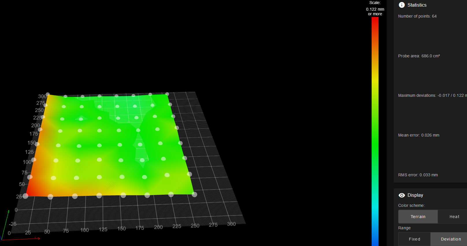
Thank you for the support.
@kiki0000 said in Mesh bed compensation issue:
@norder it turned out perfect on the entire surface really close to the sides too. Ignore that single ca 5x5 mm spot on the fron left short piece (picture is rotate 90 deg to the right now...). All around is perfect so it was jsut some grease on the plate. It is nice to work on the print surface....
I hope it will stay like this now forever

Thank you for all the support.
@norder said in Mesh bed compensation issue:
But this plan is important for you after I have calculated my level points.
At first thank you for the detailed comment again.
I have done a similar CAD drawing already in the morning the only difference was that I did not put hte G31 points onto the line pointing into the middle of the bed only the same distance from the Z axes in all 3 cases. Now I changed this according to your proposal.
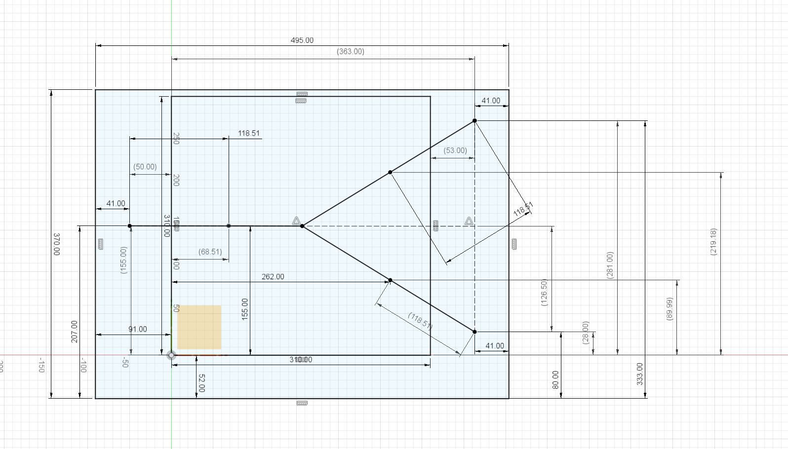
This is how it looks like (I know it i sa mess just because I wanted to put all the measurements from the frame etc onto the drawing.)
The biggest rectangle is my frame (I cannot reach with the current setup the rear 5mm of the bed this is why my max Y limit is 305. I know this is stupid because I could move the complete Z assmebly 5-10mm forward and then I could reach it but I have just done some changes and I was too lazy to do this up to now ).
The bed is clearly the 310 x 310. Furhtermore you can see the 3 outside points (41mm from the frame on both sides ) for the 3 axis and the 3 inner points on the lines now are the probing points for the G32 (262mm is my max Y reach point on the right for the BL touch).
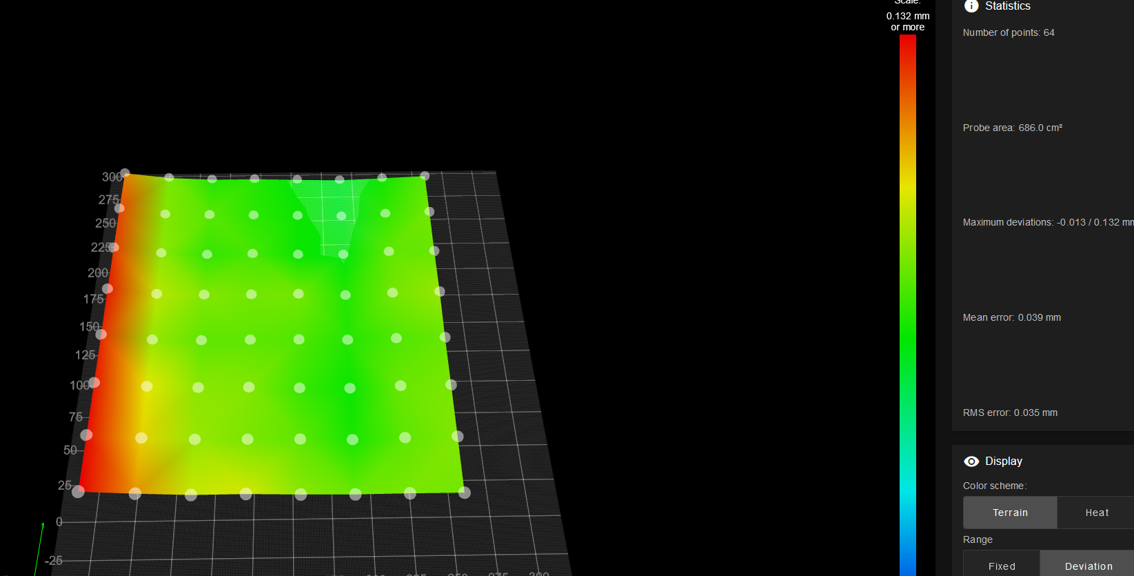
This is how my heightmap looks like with a narrow space all around (after the Y axis realignment now this is on the same level in the entire bed length but ca 0.13mm higher than the rest of teh bed.).
@norder said in Mesh bed compensation issue:
I saw that your axis limits are not quite OK.
At minimal you have a positive value (X2).
M208 X2 Y-40 Z0 S1 ; set axis minimum
And at maximum you have a value that is smaller than the actual print bed (Y303).
M208 X320 Y303 Z300 S0 ; set axis maxima
As I wrote above I am limited at 305mm at the moment because of the bed position on the actuan assembly. I will later on move the complete Z assembly forward by 10-15mm.
@norder said in Mesh bed compensation issue:
Yes, sometimes it is a bit confusing whether the offset values of the probe are taken into account or whether you have to do it yourself.
If you enter G30 without coordinates, then the probe measures where the print head is currently located.
If it is to be a specific point that is to be measured, such as X20 Y30, then you have to go there beforehand with G1 and calculate the offset yourself, i.e. G1 X78 Y30.
Your new probe offsets are included here.
Yes, little bit confusing but now I already figured out which is taking into account the offset and which not. Thanks a lot
@norder said in Mesh bed compensation issue:
I hope Google doesn't translate it into cryptic and it helps you get there.
No, it was perfect. Thanks for the lots of help again
@norder said in Mesh bed compensation issue:
Not many people have such a nice, flat and uniformly green heightmap as @rogerpodacter has, which does not mean that the first layer cannot be printed absolutely perfectly
Unfortunatley not... and this is my 2nd cast alu bed for a hell amount of money.......
@norder said in Mesh bed compensation issue:
Measure the area where the BLTouch goes after the conversion, remember the M564 command I gave you in comment #15.
Measure the points and coordinates from the example sketch.
Changing the axis limits in the config.g with the new insights from the M564 thingy.
I have done these all now I am just printing my test.
@norder said in Mesh bed compensation issue:
So I have to vote now. Today is elected here in Germany / Lower Saxony.
I hope there will be positive changes after that.
It can't go on like this.
Haha By the way I am also living in Germany at the moment (since 4 years) but I am moving in 1,5 month
@norder and @rogerpodacter after correcting the Y rail alignment the heightmap looks pretty good. No more slope on hte left side.
But my first layer is still not perfect especially on the left side.


Maybe now it is really the BL touch?
@norder and @rogerpodacter I 3D drew my printer with the correct positions and really certains things were off. Now I perfectly symmetrically defined everything. All the Z axis probe points are an eqal distance from the axes, everything is in line etc. The 3 axis automatic leveling is now really finding the right plane in no time.
This is how my heightmap looks like:
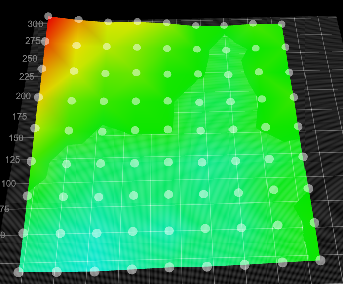
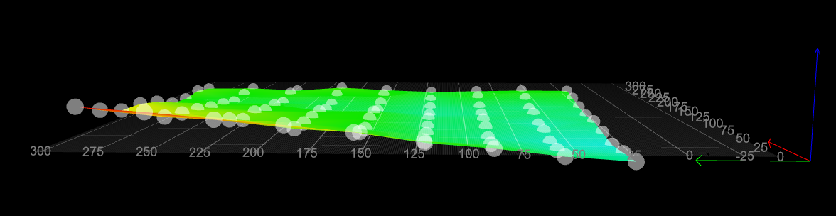
As you can see from the left view I definitely have an alignment problem with one of the Y rail. There is a nice slope in it. So I will try to compensate this now and lets see... This might have happened when I lifted up my heavy printer at the rail and put it down. Something might have shifted although I have now idea how was this possible because everything is perfectly definted by the aluminium brackets.... Lets see...
My bed.g
M561
G28
G90
			; home all axis bb
;M557 X30:280 Y64:296 S50:50                           ; define mesh grid
G30 P0 X53 Y155 Z-99999  ; probe near a leadscrew, half way along Y axis
G30 P1 X260 Y281 Z-99999  ; probe near a leadscrew, half way along Y axis
G30 P2 X260 Y28 Z-99999 S3  ; probe near a leadscrew and calibrate 3 motors
My config.g
G90                                                ; send absolute coordinates...
M83                                                ; ...but relative extruder moves
M550 P"Kikicube"                                   ; set printer name
M575 P1 S1 B57600

M669 K1                                            ; select CoreXY mode

; Network
M552 S1                                            ; enable network
M586 P0 S1                                         ; enable HTTP
M586 P1 S0                                         ; disable FTP
M586 P2 S0                                         ; disable Telnet

; Drives
M569 P0 S1                                  ; physical drive 0 goes forwards
M569 P1 S0                              ; physical drive 1 goes forwards
M569 P2 S1                                         ; physical drive 2 goes forwards
M569 P3 S0                                         ; physical drive 3 goes forwards
M569 P4 S1                                         ; physical drive 4 goes forwards
M569 P6 S0

M584 X0 Y1 Z2:4:6 E3 P3                         ; set drive mapping
M350 X16 Y16 Z16 E16 I1                            ; configure microstepping with interpolation
M92  X80.2 Y80.2 Z400.00 E882                ; set steps per mm
M566 X700.00 Y700.00 Z240.00 E2000.00                ; set maximum instantaneous speed changes (mm/min)
M203 X12000.00 Y12000.00 Z1000.00 E2000.00          ; set maximum speeds (mm/min)
M201 X3000.00 Y3000.00 Z100.00 E5600.00             ; set accelerations (mm/s^2)
;M593 F66
M906 X900 Y900 Z550 E450 I30                     ; set motor currents (mA) and motor idle factor in per cent
M84 S30                                            ; Set idle timeout
M671 X-50:363:363 Y155:281:28 S15 		  		   ; leadscrews at left and right of X axis

M572 D0 S0.03					   				   ; pressure advance 0,1
M592 D0 A-0.00971 B0.003424	   		   			   ;non-linear extrusion


; Axis Limits
M208 X2 Y-40 Z0 S1                                 ; set axis minima
M208 X320 Y303 Z300 S0                             ; set axis maxima

; Endstops
M574 X1 S1 P"xstop"                                ; configure active-high endstop for low end on X via pin xstop
M574 Y2 S1 P"ystop"                                ; configure active-high endstop for high end on Y via pin ystop
M574 Z1 S2                                         ; configure Z-probe endstop for low end on Z

; Z-Probe
M558 P9 C"^zprobe.in" H6 F300 T12000       ; set Z probe type to bltouch and the dive height + speeds
M950 S0 C"duex.pwm1"                             ; create servo pin 0 for BLTouch

G31 P500 X-58 Y0 Z2.55                             ; set Z probe trigger value, offset and trigger height
M557 X20:260 Y20:290 P9                          ; define mesh grid
;M557 X60:242 Y75:240 S40                           ; define mesh grid


; Heaters

M308 S0 P"bedtemp" Y"thermistor" T100000 B3950 R4700     ; configure sensor 0 as thermistor on pin bedtemp
M950 H0 C"bed_heat" Q10 T0                              ; create bed heater output on bedheat and map it to sensor 0
M140 H0                                            ; map heated bed to heater 0
M143 H0 S120                                       ; set temperature limit for heater 0 to 120C
M307 H0 B0 S1.00                                   ; disable bang-bang mode for the bed heater and set PWM limit

M308 S1 P"e0temp" Y"thermistor" T100000 B3950 R4700      ; configure sensor 1 as thermistor on pin e0temp
M950 H1 C"e0heat" T1                               ; create nozzle heater output on e0heat and map it to sensor 1
M143 H1 S260                                       ; set temperature limit for heater 1 to 260C
M307 H1 B0 S1.0                                 ; disable bang-bang mode for heater  and set PWM limit
M307 H1 A573.2 C177.0 D7.3 V23.8 B0 S1.0
;Heater 1 model: gain 573.2, time constant 177.0, dead time 7.3, max PWM 1.00, calibration voltage 23.8, mode PID
;Computed PID parameters for setpoint change: P7.5, I0.209, D38.6
;Computed PID parameters for load change: P7.5, I0.406, D38.6

M307 H0 A61.3 C251.9 D3.4 B0 S1.0 V23.9
;Heater 0 model: gain 61.3, time constant 251.9, dead time 3.4, max PWM 1.00, calibration voltage 23.9, mode PID
;Computed PID parameters for setpoint change: P217.1, I7.439, D513.5
;Computed PID parameters for load change: P217.1, I19.173, D513.5

; Fans
M950 F0 C"fan0" Q500                               ; create fan 0 on pin fan0 and set its frequency
M106 P0 H-1                                     ; set fan 0 value. Thermostatic control is turned off
M950 F1 C"fan1" Q500 ; create fan 1 on pin fan1 and set its frequency
M106 P1 X0.75 H1 T45    ; set fan 1 value. Thermostatic control is turned on
;M950 F8 C"duex.fan8"
;M106 P8 S250 H-1								   ; PSU cooler fan

; Tools
M563 P0 D0 H1 F0                                   ; define tool 0
G10 P0 X0 Y0 Z0                                    ; set tool 0 axis offsets
G10 P0 R0 S0                                       ; set initial tool 0 active and standby temperatures to 0C

; Custom settings are not defined

; Miscellaneous
M911 S10 R11 P"M913 X0 Y0 G91 M83 G1 Z3 E-1 F1000" ; set voltage thresholds and actions to run on power loss
;M501;
@norder said in Mesh bed compensation issue:
No, it can be compared to the spring steel plate and the PEI.
However, it is more dimensionally stable than spring steel and retains its shape after bending.
It is slightly lighter than the spring steel plate.
I just measured both plates again.
The spring steel with PEI is almost 1.8mm thick.
The black print is 1.9mm.
Thanks for the info.
I will go and grab one with a magnetic sheet and my bed magnets and the sheet magnet will grab onto each other.
@rogerpodacter said in Mesh bed compensation issue:
y 3 probe points were taken from the online example, and this gave me problems where my LEFT FRONT corner was always higher than the rest of the bed. I finally solved this issue by realizing the probe points must be symmetrical. Its all about the G29 G32 level command.
Yes, this is still my problem. I will go ahead and really define all the bed probing points and Z axis points simmetrically.
What I find a little bit strange that certain commands are taking into account the offset of the probe others not and this is nowhere really documented (at least I could not find these comments at the G29 and G32 command in the doku). Ok, for sure I can see while testing if it is off by 50mm or not but anyway it would be easier if they would all show the same.
One thing I never really tought about is that it is really important that the probe points for the 3 Z axis must also be simmetrical to everything. I thought 3 points are defining a shape and as soon as my Z axis points are properly defined it should be able to calculate from this wherever I probe. But it looks likie this i snot the case. I also started to mess with my Y rails to compensate for the bed misalignment on on side but maybe this is similarly to you not really my problem.
@norder said in Mesh bed compensation issue:
That's why I pointed out in post #6 that the measuring points in the bed.g file are not symmetrical.
I don't know the new coordinates, but @kiki0000 wrote in post #8 that he has now arranged the measuring points symmetrically.
I did not even mention to you yet that after putting my printer back to its original place mesh bed leveling wasn't perfect again. Significantly bettern then before but not perfect. So now I will really define all the probing points to
@norder said in Mesh bed compensation issue:
Do you have individual magnets permanently installed in your print bed ?
Yes, I do have individual magnets and I fear if I would order this 0,5mm FR4 sheet the magnets would bend it at each and every point. I assume this sheet in 0,5mm thickness is pretty flexible.
So I will contact with the guy.
@norder said in Mesh bed compensation issue:
This is absolutely no problem with ABS+ from Minadax, it hardly smells at all.
OK, though if it does not smell it does not mean it is healthy
@norder said in Mesh bed compensation issue:
The FR4 is only 0.5mm thick. If I set 60°C in the DWC, it also becomes 60°C in the middle and around 2°C less towards the edge.
This sounds good.
@norder said in Mesh bed compensation issue:
It's the Blackprint from Printbay
I have checked this now. I have a bed with embedded magnets. I know that in general FR4 is like resin so it is not magnetic so do I need to glue a magnetic foil onto the FR4? Or there is already 1 magnetic sheet on the FR4 sheet and they give an other one to glue onto the bed?
Because as I see I can jsut buy separately the FR4 sheet.
https://printbay.eu/Ersatzplatte-Blackprint-Magnetsystem-BP
If it works so well I will give it a go. It is not expensive at all... Those low tempeartures are super impressive too.
I will also check the filaments you proposed. I usually only use PETG and PLA. I would use ABS but at the moment I am living in a flat and I do not want to use ABS in the room Although at the end of the year we will move into our house so my options will increase.
Thank you for the detailed summary. I really appreciate it.