@jlimburg Well, here goes, i am wearing my silly hat! I had the wires switched on the sensor, switching output and ground. Interesting that the sensor LED still lit up. Fixed it, sensor works, Z-Probe now show 0 when the bed is away and 798 when the sensor LED comes on. Sorry for wasting people's time 
Best posts made by jlimburg
-
RE: Inductive sensor NPN NO not workingposted in General Discussion
Latest posts made by jlimburg
-
Error: short-to-ground detected by driver(s) 3posted in Duet Hardware and wiring
Hi all, my Duet 2 Wifi 1.04c started throwing an error yesterday

I have unplugged the extruder motor cable and replugged it but it didn't make a difference. The extruder is a Bondtech BMG-X2 that was hooked up to drivers 3+4. Here is a photo of the drivers with the cables detached
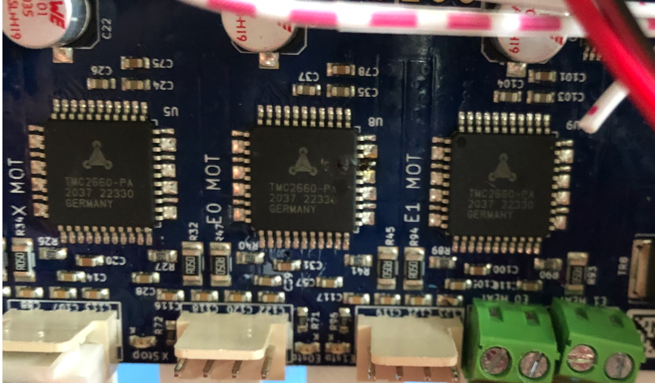
Sorry the image quality isn't great, i was the best i was able to do. I believe i see damage on the chip for driver 3 which would indicate that the chip itself is broken.The cables are the ones that came with the extruder and have worked fine before this so i don't think it is a wiring issue.
I read many posts talking about short-to-ground errors and they suggest wiring or stepper problems. I believe the wiring is ok as stated above. The stepper works fine if i plug it into driver 4 so i don't think that is the issue either. I bought the Duet from Matterhackers in March 2021 so i think it is still under warranty but i am not sure if this is covered.Also, here is the config.g:
; Configuration file for Duet WiFi (firmware version 3.3)
; executed by the firmware on start-up
;
; generated by RepRapFirmware Configuration Tool v3.3.5 on Mon Nov 01 2021 14:14:16 GMT-0700 (PDT); General preferences
G90 ; send absolute coordinates...
M83 ; ...but relative extruder moves
M550 P"My Printer" ; set printer name
M669 K1 ; select CoreXY mode; Network
M552 S1 ; enable network
M586 P0 S1 ; enable HTTP
M586 P1 S0 ; disable FTP
M586 P2 S0 ; disable Telnet; Drives
M569 P0 S0 ; physical drive 0 goes backwards
M569 P1 S0 ; physical drive 1 goes backwards
M569 P2 S1 ; physical drive 2 goes forwards
M569 P3 S0 ; physical drive 3 goes backwards
M569 P4 S0 ; physical drive 4 goes backwards
M584 X0 Y1 Z2 E3:4 ; set drive mapping
M350 X16 Y16 Z16 E16:16 I1 ; configure microstepping with interpolation
M92 X80.00 Y80.00 Z400.00 E415:415 ; 476.50 ; set steps per mm
M566 X900.00 Y900.00 Z12.00 E600.00 ; set maximum instantaneous speed changes (mm/min)
M203 X9000.00 Y9000.00 Z600.00 E6000.00 ; set maximum speeds (mm/min)
M201 X800.00 Y800.00 Z250.00 E800.00 ; set accelerations (mm/s^2)
M906 X700 Y700 Z700 E700 I30 ; set motor currents (mA) and motor idle factor in per cent
M84 S30 ; Set idle timeout; Axis Limits
M208 X0 Y0 Z0 S1 ; set axis minima
M208 X360 Y360 Z500 S0 ; set axis maxima; Endstops
M574 X1 S1 P"xstop" ; configure switch-type (e.g. microswitch) endstop for low end on X via pin xstop
M574 Y1 S1 P"ystop" ; configure switch-type (e.g. microswitch) endstop for low end on Y via pin ystop
M574 Z1 S2 ;P"zstop" ; configure Z-probe endstop for low end on Z; Z-Probe
M950 S0 C"exp.heater3" ; Duet 2 WiFi/Ethernet
M558 P9 C"^zprobe.in" H3 F200 T6000 ; set Z probe type to unmodulated and the dive height + speeds
G31 X20 Y0 Z1.97 P25 ; set Z probe trigger value, offset and trigger height
M557 X15:215 Y15:215 S50 ; define mesh grid; Heaters
M308 S0 P"bedtemp" Y"thermistor" T100000 B4138 ; configure sensor 0 as thermistor on pin bedtemp
M950 H0 C"bedheat" T0 ; create bed heater output on bedheat and map it to sensor 0
;M307 H0 B1 S1.00 ; enable bang-bang mode for the bed heater and set PWM limit
M307 H0 B0 R0.214 C688.7 D10.82 S1.00 V23.6
M140 H0 ; map heated bed to heater 0
M143 H0 S120 ; set temperature limit for heater 0 to 120C
M308 S1 P"e0temp" Y"thermistor" T100000 B4138 ; configure sensor 1 as thermistor on pin e0tempM950 H1 C"e0heat" T1 ; create nozzle heater output on e0heat and map it to sensor 1
M307 H1 B0 S1.00 ; disable bang-bang mode for heater and set PWM limit
M143 H1 S280 ; set temperature limit for heater 1 to 280C
M308 S2 P"e1temp" Y"thermistor" T100000 B4138 ; configure sensor 1 as thermistor on pin e1temp
M950 H2 C"e1heat" T2 ; create nozzle heater output on e1heat and map it to sensor 2
M307 H2 B0 S1.00 ; disable bang-bang mode for heater and set PWM limit
M143 H2 S280 ; set temperature limit for heater 1 to 280C; Fans
M950 F0 C"fan0" Q500 ; create fan 0 on pin fan0 and set its frequency
M106 P0 S1 H1 T180 ; set fan 0 value. Thermostatic control is turned off
M950 F1 C"fan1" Q500 ; create fan 1 on pin fan1 and set its frequency
M106 P1 S1 H1 T80 ; set fan 1 value. Thermostatic control is turned on; Tools
M563 P0 D0 H1 F0 L0 ; define tool 0
G10 P0 X0 Y0 Z0 ; set tool 0 axis offsets
G10 P0 R0 S0 ; set initial tool 0 active and standby temperatures to 0C
M563 P1 D1 H2 F0 L1 ; define tool 1
G10 P1 X20 Y0 Z0 ; set tool 1 axis offsets
G10 P1 R0 S0 ; set initial tool 1 active and standby temperatures to 0C -
RE: Inductive sensor NPN NO not workingposted in General Discussion
@jlimburg Well, here goes, i am wearing my silly hat! I had the wires switched on the sensor, switching output and ground. Interesting that the sensor LED still lit up. Fixed it, sensor works, Z-Probe now show 0 when the bed is away and 798 when the sensor LED comes on. Sorry for wasting people's time
-
RE: Inductive sensor NPN NO not workingposted in General Discussion
@fcwilt Thanks for sharing the link! I'll order a couple from them
")
-
RE: Inductive sensor NPN NO not workingposted in General Discussion
@fcwilt Thanks, i tried that, unfortunately it made no difference. I am starting to think my sensor is faulty. I'll order another one and try that.
-
Inductive sensor NPN NO not workingposted in General Discussion
Hi all, and apologies if this has already been answered. I believe i did a thorough search but may have missed something.
I connected an inductive sensor to my Duet Wifi, revision 1.04C running firmware 3.3, VIN 24V. The sensor is a NPN NO with 6-36V. I connected the wires according to the wiki, brown and black to VIN / Ground, respectively, and blue to the Z probe input pin in the Z Probe terminal.Here are my FW settings:
; Endstops
M574 X1 S1 P"xstop" ; configure switch-type (e.g. microswitch) endstop for low end on X via pin xstop
M574 Y1 S1 P"ystop" ; configure switch-type (e.g. microswitch) endstop for low end on Y via pin ystop
M574 Z1 S2 ;P"zstop" ; configure Z-probe endstop for low end on Z; Z-Probe
M558 P1 C"!zprobe.in" H5 F300 T6000
G31 P7 X100 Y100 Z-0I tried M558 with P5 as described in the wiki but that just shows '0' in the Z Probe field no matter if the probe LED is on or not. If i use P1 i at least get something, the Z Probe indictor show 6-7 when warm (?) so i can trigger on 7 and that works. The issue is that the 6-7 value is not reliable, on startup it show 30-50 and then slowly wanders down to 6, sometimes 7 even when there is no proximity to the bed.
My Z-Probe output is connected directly, no diode or resistors since i have 1.04C they should not be required.I measured the Z-Probe output with a multimeter and it has 0V when there is no proximity to the bed and 0.5V when the bed is near and the probe LED is on.
Any help with this would be appreciated!