Duet3D Logo Duet3D
    • Tags
    • Documentation
    • Order
    • Register
    • Login
    1. Home
    2. AV13091
    • Profile
    • Following 0
    • Followers 0
    • Topics 3
    • Posts 16
    • Best 0
    • Controversial 0
    • Groups 0

    AV13091

    @AV13091

    0
    Reputation
    3
    Profile views
    16
    Posts
    0
    Followers
    0
    Following
    Joined Last Online

    AV13091 Unfollow Follow

    Latest posts made by AV13091

    • RE: Duet Ethernet from 12V to 24v

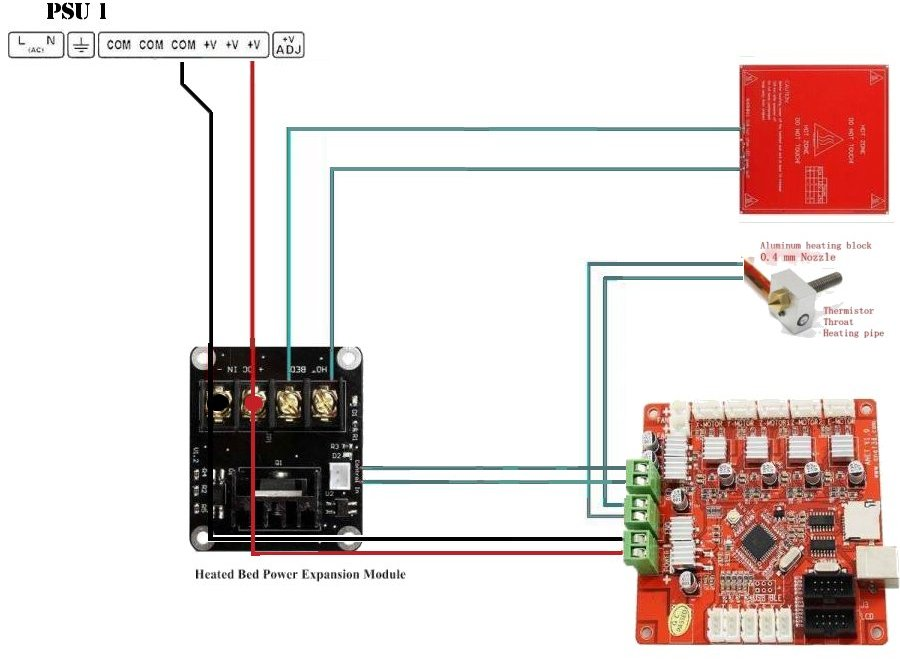
      EDIT : after a while, I had time to finish this project and found this topic about how to connect a MOSFET to a ramps :
      https://3dprint.wiki/reprap/electronics/heatbed_mosfet

      long story short, if you use a MOSFET for your bed and/or your extruder, you "just" have to connect the signalwire (the control input of the MOSFET) form the MOSFET directly to the bed output from your duet.
      Here is the picture from the link.
      special thanks to 3Dprintwiki !

      a187d04e-9366-4829-8a40-5c71ec614ec9-image.png

      posted in Duet Hardware and wiring
      AV13091undefined
      AV13091
    • RE: Duet Ethernet from 12V to 24v

      @bearer
      Don't worry, you already help me a lot !
      once again, thank you :).

      Axel.

      posted in Duet Hardware and wiring
      AV13091undefined
      AV13091
    • RE: Duet Ethernet from 12V to 24v

      Hello Bearer, thank you for your answer.

      the dc/dc converter is a neat idea but i think it will be a good occasion to replace all my old stuff and buy new one in 24V !

      you're totally right about the heaters, even more for the bed who need 21 amps to works, knowing that the duet is limited to 18A, I will re-use the external MOSFET that is already place in the Chiron. Thanks for the remark, I totally forgot.

      one last question :

      on the chiron trigorilla board, the MOSFET are controled directly from the "board" output on the card (see the image below).

      Can I do the same with the duet ethernet ?

      once again, thank you for your help.

      Axel.

      ![0_1596529255398_Trigorilla png.png](Uploading 100%)

      edit: seems like i can't upload the image, here's a link where you can see the "board" connection from the trigorilla, this one is directly connected to the "control" pin from the MOSFET

      board : https://www.anycubic.com/products/trigorilla-motherboard-for-mega-kossel
      see the second picture
      MOSFET : https://www.amazon.fr/ANYCUBIC-lalimentation-chauffant-ULTRABASE-limprimante/dp/B07S7QFPNJ
      see the second picture too

      posted in Duet Hardware and wiring
      AV13091undefined
      AV13091
    • Duet Ethernet from 12V to 24v

      Hello everyone,

      I have a duet ethernet 1.02 and has always use it with a 12V PSU.
      I've bought an Anycubic Chiron and I'm looking to swap the actual Trigorilla with my duet.

      I didn't find anything saying obviously that if you feed the duet with 24v, all the electronics (fan, heater cartridge, etc...) must be 24v too.
      I know my question will be quite obvious but if I feed the duet with 24v, do i need to change all my previous electronics with 24v ones ?

      thank you in advance,

      Axel.

      posted in Duet Hardware and wiring
      AV13091undefined
      AV13091
    • RE: Diagonal rod length impact on Z dimension

      @Veti
      Okay, I understand now, I'm using a classic S6 factor :).
      I will for sure run a delta calibration but I would like to approach the real values first (effector's tilt, and other problems can give bad results).

      posted in Tuning and tweaking
      AV13091undefined
      AV13091
    • RE: Diagonal rod length impact on Z dimension

      @dc42
      Thanks for your answer,
      it's not that huge (49.5mm instead of 50mm). What bothers me is that I had an exact 50mm before troubleshooting the diagonal rod.
      I wasn't sure about its impact on the Z dimension as I always took for granted that the diagonal rod only affects the X and Y dimensions.

      Anyway, now that i'm sure about this, I will take care of the rest (my belts are quite old and could be too loose).

      Again, thanks for your help.

      Axel.

      posted in Tuning and tweaking
      AV13091undefined
      AV13091
    • RE: Diagonal rod length impact on Z dimension

      @Veti
      Thanks for your answer,
      That's the idea, i don't use any compensation tools, i'm targeting an exact value (as close as possible) before using any compensations.

      posted in Tuning and tweaking
      AV13091undefined
      AV13091
    • Diagonal rod length impact on Z dimension

      Hello everyone,

      I've always considered that the diagonal rod length only modifies the XY dimensions while the Z dimensions is impact with the steps/mm. While calibrating the diagonal rod lenght, I've notice that my Z dimensions is not accurate anymore.

      Can someone confirm (or not) that the diagonal rod length only modifies the XY dimensions ?

      NB : I want to have it as close as possible before using the M579 command.

      Thank you !
      Axel.

      posted in Tuning and tweaking
      AV13091undefined
      AV13091
    • RE: Endstop compensation

      Hello,

      thank you for your help, I wouldn't find this out without you !

      Have a good day,

      Axel.

      posted in Tuning and tweaking
      AV13091undefined
      AV13091
    • RE: Endstop compensation

      Hello,

      I use an offset for my extruder, well see ! (I have a chimera with only one extruder for now, I plan to mount the second in a few week).
      As you expected their is an offset of X=9, what a coincidence 😄 !

      As you've ask for, here is my config.g :

      ; Configuration file for Duet 0.8.5 (firmware version 1.17 to 1.19)
      ; executed by the firmware on start-up
      ;
      ; generated by RepRapFirmware Configuration Tool on Fri Mar 16 2018 19:46:10 GMT+0100 (Paris, Madrid)

      ; General preferences
      G90 ; Send absolute coordinates...
      M83 ; ...but relative extruder moves

      ;*** The homed height is deliberately set too high in the following - you will adjust it during calibration.
      M665 L269.000 R164.761 H299.868 B140.0 ; Set delta radius, diagonal rod length, printable radius and homed height
      M666 X0 Y0 Z0 A0.00 B0.00 ; Put your endstop adjustments here, or let auto calibration find them

      ; Network
      M550 PDelta Kossel ; Set machine name
      M551 PAvoriaz2804 ; Set password
      M540 PBE:EF:DE:AD:FE:ED ; Set MAC address
      M552 P192.168.0.90 S1 ; Enable network and acquire dynamic address via DHCP
      M586 P0 S1 ; Enable HTTP
      M586 P1 S0 ; Disable FTP
      M586 P2 S0 ; Disable Telnet

      ; Drives
      M569 P0 S0 ; Drive 0 goes forwards
      M569 P1 S0 ; Drive 1 goes forwards
      M569 P2 S0 ; Drive 2 goes forwards
      M569 P3 S0 ; Drive 3 goes forwards
      M92 X80 Y80 Z80 E87.059 ; Set steps per mm E476.5
      M566 X1200 Y1200 Z1200 E1200 ; Set maximum instantaneous speed changes (mm/min)
      M203 X18000 Y18000 Z18000 E1200 ; Set maximum speeds (mm/min)
      M201 X1000 Y1000 Z1000 E1000 ; Set accelerations (mm/s^2)
      M906 X800 Y800 Z800 E800 I30 ; Set motor currents (mA) and motor idle factor in per cent AVANT 1200
      M84 S30 ; Set idle timeout

      ; Axis Limits
      M208 Z-0.1 S1 ; Set minimum Z

      ; Endstops
      M574 X2 Y2 Z2 S1 ; Set active high endstops

      ; Z-Probe
      M558 P1 X0 Y0 Z0 H4 F120 T4000 ; Set Z probe type to switch, the axes for which it is used and the dive height + speeds
      G31 P500 X0 Y0 Z2.90 ; Set Z probe trigger value, offset and trigger height
      M557 R85 S20 ; Define mesh grid

      ; Heaters
      M301 H0 S1.00 P10 I0.1 D200 T0.4 W180 B30 ; Use PID on bed heater (may require further tuning)
      M307 H1 A271.6 C131.5 D4.8 S1.00 B0 ;
      ; M307 H2 A271.6 C131.5 D4.8 S1.00 B0 ;

      M305 P0 T100000 B3950 C0 R4700 ; Set thermistor + ADC parameters for heater 0
      M143 H0 S120 ; Set temperature limit for heater 0 to 120C

      M305 P1 T100000 B4388 C0 R4700 ; Set thermistor + ADC parameters for heater 1
      M143 H1 S280 ; Set temperature limit for heater 1 to 280C

      ; M305 P2 T100000 B4388 C0 R4700 ; Set thermistor + ADC parameters for heater 2
      ; M143 H2 S280 ; Set temperature limit for heater 2 to 280C

      ; Fans
      M106 P0 S0 I0 F500 H-1 ; Set fan 0 value, PWM signal inversion and frequency. Thermostatic control is turned off
      M106 P1 T45 H1 ; Set fan 1 value, PWM signal inversion and frequency. Thermostatic control is turned ON : 45°C

      ; Tools
      M563 P0 D0 H1 ; Define tool 0
      G10 P0 X9 Y0 Z0 ; Set tool 0 axis offsets
      G10 P0 R0 S0 ; Set initial tool 0 active and standby temperatures to 0C

      ; M563 P1 D0 H2 ; Define tool 1
      ; G10 P1 X-9 Y0 Z0 ; Set tool 1 axis offsets
      ; G10 P1 R0 S0 ; Set initial tool 0 active and standby temperatures to 0C

      ; Custom settings are not configured

      ; Miscellaneous
      T0 ; Select first tool
      ; T1 ; Select second tool

      If I'm right I have to make it X=0 in my tool section ?
      posted in Tuning and tweaking
      AV13091undefined
      AV13091