@64bit This worked amazingly thanks!
Posts made by jordna.le1299
-
RE: Duet 2 Locked out of WIFIposted in Firmware installation
@jordna-le1299 said in Duet 2 Locked out of WIFI:
Earlier today I was trying to update from RRF2.05 to RRF3.0. I used DWC1 to upload the zip file with no luck. I then tried to use M997 S0 with the firmware with also no luck. Now when I start the duet there is no wifi page and it seems the wifi module is stuck. Here are the logs on YAT. I was wondering if anyone could help me because now I am locked out of the duet. Did I somehow corrupt the firmware? If so can I reinstall it?

To add onto it I have tried the sd card of a different working duet and that also did not work on the board. This leads me to think it is firmware related.
-
Duet 2 Locked out of WIFIposted in Firmware installation
Earlier today I was trying to update from RRF2.05 to RRF3.0. I used DWC1 to upload the zip file with no luck. I then tried to use M997 S0 with the firmware with also no luck. Now when I start the duet there is no wifi page and it seems the wifi module is stuck. Here are the logs on YAT. I was wondering if anyone could help me because now I am locked out of the duet. Did I somehow corrupt the firmware? If so can I reinstall it?

-
RRF 3.X to RRF 2.Xposted in Firmware installation
Hi I was looking around the forums and I can't seem to find a comprehensive guide of downgrading the firmware. I want to downgrade the firmware for testing purposes. It seems to output this error each time I upload the firmware
Error: M997: In-application programming binary "Duet2_SDiap32_WiFiEth.bin" not found
Is there a way to get around this?
-
RE: Output Step and Directionposted in Duet Hardware and wiring
Ah so yea, so we're building a multi-axis printer. The problem here is that all the pins for that specific expansion board we're using are being taken up by servos. This is where my external board comes in, it has it's own driver and controller built in to drive an axis motor, and can be controlled by an external master using step and direction. Is this possible with duet, to just output step and direction from those lcd pins (STP/DIR (10 and 11))
-
Output Step and Directionposted in Duet Hardware and wiring
Hi, right now I have an external driver that can take a step and direction output from a controller board like a Duet. I'm using a duet 2 ethernet and I see that there is a step an direction channel coming out of the lcd pins. I was wondering how I can get those to output step and direction either through the the web_ui or other methods. Thanks!
-
RE: Using GPIO on duet 3posted in Duet Hardware and wiring
You could specify the button height as the trigger height of the probe, then it would be taken into account automatically.
would this be done through the G31 command in config? Also to trigger it would I use the single z-probe command (G30)
I don't think the Z probe last stop height is currently stored in the OM, but I could add it.
Through a firmware update?
-
RE: Using GPIO on duet 3posted in Duet Hardware and wiring
@dc42 if I wanted to store the offset and use it as a variable instead how would I do so. The reason why is because rather than the button being at the bed it would actually be at some known height above it. Therefore I would be able to use that number and offset it from the true height.
-
RE: Using GPIO on duet 3posted in Duet Hardware and wiring
@jordna-le1299
Ok so I got the z-probes to work independently now. However, now when I probe and store into a point (P0) where can I use this value to put it into my nozzle offset? -
RE: Using GPIO on duet 3posted in Duet Hardware and wiring
could you try to reformulate this?

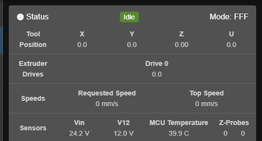
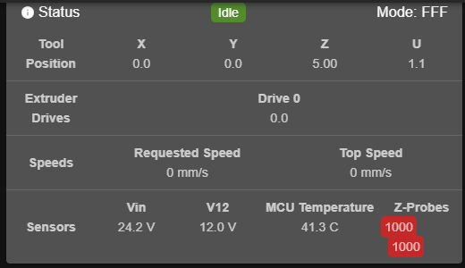
This is what shows up currently config file. However, when I trigger the inductive probe and only the inductive probe this is what shows up

It acts as the same probe even though they are seperate K's when declaring. And the switch does nothing to the z-probe itsef.
preferred method is usually a normally closed switch between ground and the input pin with pull up enabled.
as for this could I use a normally open switch and invert it in the config file making it
C"^!io1.in"Finally with the links it doesn't seem to address how to declare the separate probes. With my current code am I doing it correctly or should something be changed?
Thanks
-
Using GPIO on duet 3posted in Duet Hardware and wiring
I wanted to know how to hook up a switch to the GPIO on a duet 3. In theory I am trying to nozzle probe and bed probe as two separate probes. With bed probing I am using an inductive sensor, for nozzle probing, I am experimenting with a simple push button.
Hardware wise when the nozzle pushes on the push button it shorts the 5V pin to the Input of the GPIO. This will send a voltage high triggering the z-probe saving the height.
As for firmware I have the following code in my config.g
; Z-Probe
M558 K0 P8 C"io8.in" H4 F5000 T18000 I1 A3 ; Set Z probe type to switch and the dive height + speeds
G31 K0 P950 X-20 Y-1 Z0.4 ; Set Z probe trigger value, offset and trigger height (lowering number raises nozzle)
M557 K0 X20:380 Y40:430 S60 ; Define mesh grid; Nozzle Offset
M558 K1 P5 C"io1.in" H0 F5000 T18000 I1 A3
G31 K0 P950Right now on the duet it triggers both z-probes as i trigger the inductive and nothing happens when I push the switch. Does anyone have any insight on how to tacklet this?