@T3P3Tony I will test as soon as I can on all issues noted.
Posts made by Kiolia
-
RE: [3.6.0-beta.1] Heater feedforward not workingposted in Beta Firmware
-
RE: Implement M309 Feedforward for remote heatersposted in Firmware wishlist
@T3P3Tony I will test as soon as I can.
-
RE: [3.6.0-beta.1] Heater feedforward not workingposted in Beta Firmware
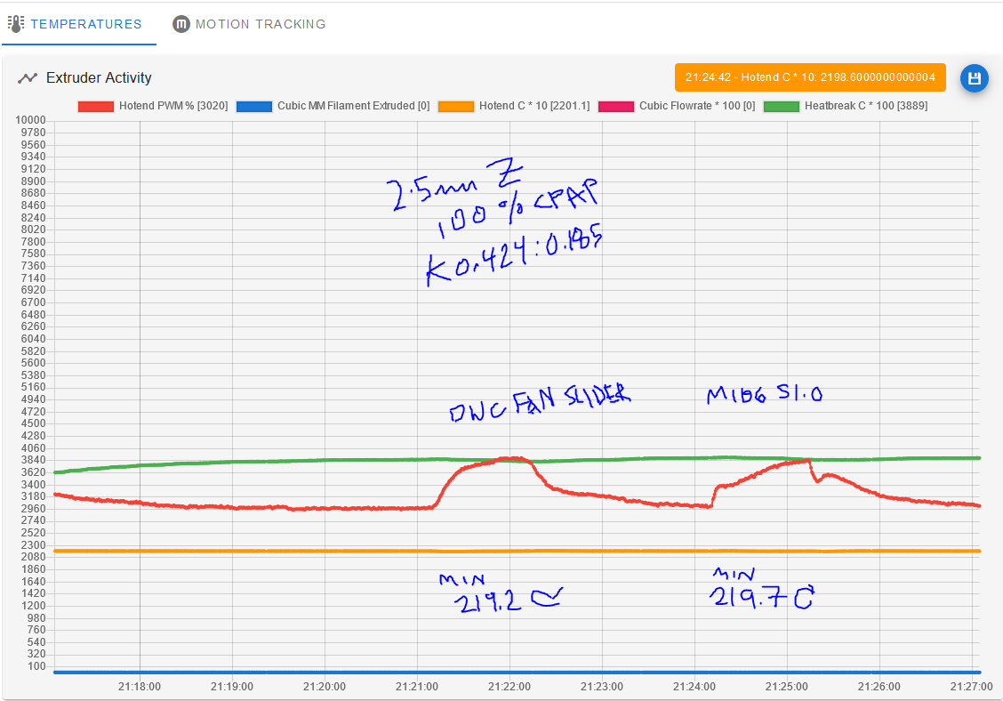
@chrishamm droftarts asked me to test that (in the beta.1) and M106 without a P does appear to trigger cooling compensation behavior where the DWC fan controls do not. These were two ~1-minute CPAP bursts activated in those two ways:
-
RE: [3.6.0-beta.1] Heater feedforward not workingposted in Beta Firmware
@droftarts @dc42 I hate to be a bother, but it seems related -- would it be possible for you to check the code that compensates for tool cooling based on the second K term set by M307? I have a growing suspicion that this isn't working, either.
Source/testing: I was hoping to use second K manipulation as a backdoor patch for missing feedforward, but after 30 minutes of testing, I can't see any difference in the temp drops or PWM reactions to a range of second K's from .05 to .485. In each test case, without moving the head (from 1mm Z), the application of full CPAP knocked temps down by the same amount (+/-5%), ramp to the new PWM level took about the same amount of time, recovery of the hot end to commanded temp took about the same amount of time, and stability of the temps after regaining commanded temp looked about the same.
I started doing diagnostics like sending M307 H1 to check the actual applied tuning values, then realized this was a little too similar to my last round of feedforward testing and figured I'd better ask.
One thing I did not test was un-selecting the tool and re-selecting it between M307's, if that matters.
The range of values I tested went from fairly lower than ideal to fairly higher. Most recent tune value, done tonight at the same toolhead location, was M307 H1 R3.181 K0.424:0.185 D4.11 E1.35 S1.00 B0. I have not changed my machine setup or firmware version since that described in the original post above. (Edit: and yes, the hotend is that efficient and windproofed. I've invested a lot of effort in optimizing thermal efficiency.)
EDIT 2: this testing was done in 3.6.0-beta.1. I cannot say for certain if it was working or not in -alpha.5+1. I believe it was working in 3.5.1, but at the time I wasn't running as aggressive of cooling profiles in any print tests, so it's hard to say. I've been having difficulties with updates, so I'd prefer not to roll back to verify behavior.
EDIT 3: I will also note that I did my testing with fan setting via the DWC fan controls, not by sending Gcode commands, if that matters.
-
RE: [3.6.0-beta.1] installation issues (SOLVED) heads up only.posted in Beta Firmware
@droftarts I walked away and remembered more about the additional error messages I saw the first time. At the time, I had the hot end and thermistor on the toolboard, and at least one message flashed about the heater being not detected (or disconnected or not found, something like that).
-
RE: [3.6.0-beta.1] installation issues (SOLVED) heads up only.posted in Beta Firmware
@droftarts I can try updating the bootloader for the beta.2 release and see how it goes, but I don't see anything in the git release history to indicate changes related to update behavior or support for 3HC boards of my version ...
EDIT, saw your edit, haha. I will stick with unplugging the CANBoard for now.BTW: I thought I saw other messages on the first incident, but I can't recall specifics. However, I remember them giving me a gut feeling this might be related to the CANBoard not restarting upon command?
-
RE: [3.6.0-beta.1] installation issues (SOLVED) heads up only.posted in Beta Firmware
@droftarts My M122 B1:
M122 B1
Diagnostics for board 1:
Duet EXP3HC rev 1.02 or later firmware version 3.6.0-beta.1 (2024-09-24 08:51:17)
Bootloader ID: SAME5x bootloader version 2.4 (2021-12-10)
All averaging filters OK
Never used RAM 170244, free system stack 202 words
Tasks: Move(3,nWait 7,0.0%,181) TMC(2,nWait 6,7.0%,95) HEAT(2,nWait 6,0.0%,133) CanAsync(5,nWait 4,0.0%,66) CanRecv(3,nWait 1,0.0%,79) CanClock(5,nWait 1,0.0%,69) MAIN(1,running,91.8%,322) IDLE(0,ready,0.0%,39) AIN(2,delaying,1.1%,264), total 100.0%
Owned mutexes:
Last reset 00:00:27 ago, cause: power up
Last software reset data not available
Moves scheduled 0, hiccups 0 (0.00/0.00ms), segs 0, step errors 0 (types 0x0), maxLate 0 maxPrep 0, ebfmin 0.00 max 0.00
Peak sync jitter -4/3, peak Rx sync delay 180, resyncs 0/0, no timer interrupt scheduled, next step interrupt due in 4273967492 ticks, disabled
VIN voltage: min 48.4, current 48.5, max 48.5
V12 voltage: min 12.4, current 12.4, max 12.5
MCU temperature: min 21.6C, current 24.0C, max 24.0C
Driver 0: pos 0, 80.0 steps/mm, standstill, SG min 0, mspos 8, reads 42950, writes 11 timeouts 0
Driver 1: pos 0, 551.0 steps/mm, standstill, SG min 0, mspos 4, reads 42945, writes 16 timeouts 0
Driver 2: pos 0, 551.0 steps/mm, standstill, SG min 0, mspos 4, reads 42946, writes 16 timeouts 0
Last sensors broadcast 0x00003018 found 4 9 ticks ago, 0 ordering errs, loop time 0
CAN messages queued 446, send timeouts 0, received 255, lost 0, ignored 0, errs 0, boc 0, free buffers 38, min 38, error reg 0
dup 0, oos 0/0/0/0, bm 0, wbm 0, rxMotionDelay 0
and M122:
M122 === Diagnostics === RepRapFirmware for Duet 3 MB6HC version 3.6.0-beta.1 (2024-09-24 10:07:51) running on Duet 3 MB6HC v1.02 or 1.02a (standalone mode) Board ID: 08DJM-9P63L-DJMSS-6J1F8-3SN6S-9VHBB Used output buffers: 3 of 40 (36 max) === RTOS === Static ram: 136444 Dynamic ram: 121388 of which 396 recycled Never used RAM 70468, free system stack 194 words Tasks: NETWORK(2,nWait 7,24.3%,225) ETHERNET(5,nWait 7,0.0%,661) HEAT(3,nWait 6,0.0%,361) Move(4,nWait 6,0.0%,333) TMC(4,nWait 6,3.0%,386) CanReceiv(6,nWait 1,0.0%,794) CanSender(5,nWait 7,0.0%,334) CanClock(7,delaying,0.0%,353) MAIN(1,running,72.4%,440) IDLE(0,ready,0.2%,29) USBD(3,blocked,0.0%,142), total 100.0% Owned mutexes: === Platform === Last reset 00:01:39 ago, cause: power up Last software reset at 2024-10-06 13:14, reason: User, Gcodes spinning, available RAM 70468, slot 1 Software reset code 0x0003 HFSR 0x00000000 CFSR 0x00000000 ICSR 0x00400000 BFAR 0x00000000 SP 0x00000000 Task MAIN Freestk 0 n/a Error status: 0x00 Aux0 errors 0,0,0 MCU temperature: min 11.7, current 24.5, max 24.7 Supply voltage: min 48.2, current 48.3, max 48.5, under voltage events: 0, over voltage events: 0, power good: yes 12V rail voltage: min 12.0, current 12.3, max 12.8, under voltage events: 0 Heap OK, handles allocated/used 99/1, heap memory allocated/used/recyclable 2048/16/0, gc cycles 0 Events: 0 queued, 0 completed Date/time: 2024-10-15 07:36:02 Slowest loop: 22.41ms; fastest: 0.07ms USB interrupts 3 === Storage === Free file entries: 20 SD card 0 detected, interface speed: 25.0MBytes/sec SD card longest read time 0.8ms, write time 0.0ms, max retries 0 === Move === Segments created 0, maxWait 0ms, bed comp in use: none, height map offset 0.000, hiccups added 0 (0.00/0.00ms), max steps late 0, ebfmin 0.00, ebfmax 0.00 Pos req/act/dcf: 252749.00/252749/0.00 252749.00/252749/0.00 252749.00/252749/0.00 next step interrupt due in 256 ticks, disabled Driver 0: standstill, SG min n/a, mspos 4, reads 2735, writes 18 timeouts 0 Driver 1: standstill, SG min n/a, mspos 4, reads 2735, writes 18 timeouts 0 Driver 2: standstill, SG min n/a, mspos 4, reads 2735, writes 18 timeouts 0 Driver 3: standstill, SG min n/a, mspos 4, reads 2735, writes 18 timeouts 0 Driver 4: standstill, SG min n/a, mspos 4, reads 2735, writes 18 timeouts 0 Driver 5: standstill, SG min n/a, mspos 4, reads 2735, writes 18 timeouts 0 Phase step loop runtime (us): min=0, max=5, frequency (Hz): min=1973, max=2027 === DDARing 0 === Scheduled moves 0, completed 0, LaErrors 0, Underruns [0, 0, 0] === DDARing 1 === Scheduled moves 0, completed 0, LaErrors 0, Underruns [0, 0, 0] === Heat === Bed heaters 0 -1 -1 -1 -1 -1 -1 -1 -1 -1 -1 -1, chamber heaters -1 -1 -1 -1 -1 -1 -1 -1, ordering er=== GCodes === Movement locks held by null, null HTTP is idle in state(s) 0 Telnet is idle in state(s) 0 File is idle in state(s) 0 USB is idle in state(s) 0 Aux is idle in state(s) 0 Trigger is idle in state(s) 0 Queue is idle in state(s) 0 LCD is idle in state(s) 0 SBC is idle in state(s) 0 Daemon is idle in state(s) 0 Aux2 is idle in state(s) 0 Autopause is idle in state(s) 0 File2 is idle in state(s) 0 Queue2 is idle in state(s) 0 Q0 segments left 0, axes/extruders owned 0x0000000 Code queue 0 is empty Q1 segments left 0, axes/extruders owned 0x0000000 Code queue 1 is empty === CAN === Messages queued 904, received 1604, lost 0, ignored 0, errs 0, boc 0 Longest wait 3ms for reply type 6024, peak Tx sync delay 4, free buffers 50 (min 49), ts 500/499/0 Tx timeouts 0,0,0,0,0,0 === Network === Slowest loop: 26.17ms; fastest: 0.03ms Responder states: MQTT(0) HTTP(0) HTTP(0) HTTP(0) HTTP(0) HTTP(0) HTTP(0) FTP(0) Telnet(0) Telnet(0) HTTP sessions: 1 of 8 = Ethernet = Interface state: establishingLink Error counts: 0 0 0 0 0 0 Socket states: 0 0 0 0 0 0 0 0 0 === WiFi === Interface state: active Module is connected to access point Failed messages: pending 0, notrdy 0, noresp 0 Firmware version 2.1.0 MAC address 70:04:1d:be:ad:dc Module reset reason: Power up, Vcc 0.00, flash size 16777216, free heap 223308 WiFi IP address 192.168.1.206 Signal strength -44dBm, channel 3, mode 802.11n, reconnections 0 Clock register 00002002 Socket states: 0 0 0 0 0 0 0 0 === Multicast handler === Responder is inactive, messages received 0, responses 0 -
RE: [3.6.0-beta.1] installation issues (SOLVED) heads up only.posted in Beta Firmware
@Mr-Crispin I have a 6HC with 3HC toolboard, standalone mode. I have had almost the same exact experience twice, once when going from 3.4.x to 3.5.1 and once when going from 3.6.0-alpha5+1 to 3.6.0-beta.1. Somehow I was able to avoid it when going from 3.5.1 to the 3.6.0-alpha. I believe it helped to have my CANBoard unplugged when I updated the mainboard, but I will have to verify this next time I update.
The first time it happened, I had attempted to update mainboard and toolboard together; the second time it happened, I had tried to update the mainboard by itself, but still had the CANBoard plugged in. Both times were terrifying and made me think I'd bricked my 6HC.
As supplemental info, I got this message both times this happened to me, but it never appeared in the console log:
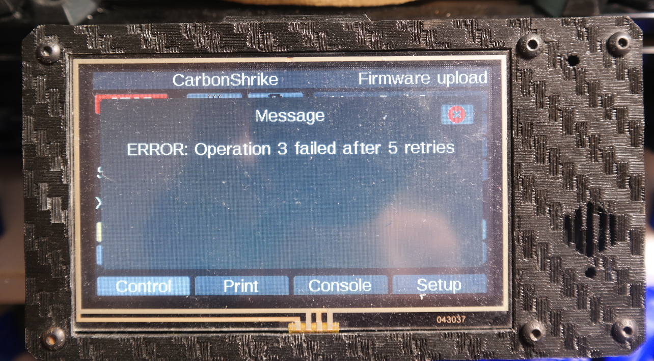
After this, the printer posted no further updates for 15-20 minutes, whereupon I restarted it, and from there the PanelDue would show the usual control screen, except with 0's in all values (as if it had not loaded config.g), and was completely nonresponsive on the console as well as inaccessible via DWC. I had to go through Bossa to reflash in both cases.
-
RE: [3.6.0-beta.1] Heater feedforward not workingposted in Beta Firmware
@dc42 Legendary, thank you! I'll be watching for the next update and ready to test.
-
RE: [3.6.0-beta.1] Heater feedforward not workingposted in Beta Firmware
@droftarts Bummer, okay. Would it be (feed)forward (sorry) of me to ask if the fix might make it into the 3.6.0 release? Also, do I need to do anything to flag the forum topic closed/etc.?
-
RE: [3.6.0-beta.1] Heater feedforward not workingposted in Beta Firmware
@droftarts Thanks! I figured that with all the 3.6.0 changes, it would have been easy for a link to something like feedrate to become broken, but it also seems like something unit testing ought to catch unless it's specific to a weird edge case like mine of the Extruder being the only aspect of extrusion not being controlled by the mainboard.
I appreciate your attention on this one. It's not quite a blocking issue for my use case but it's a significant QOL (and QOPrinting!) impact.
-
RE: [3.6.0-beta.1] Heater feedforward not workingposted in Beta Firmware
@droftarts I wasn't aware DC had done any work toward it. If so, is it possible a requirement was inadvertently added that E and heater/therm need to be on the same board? I could revert my wiring updates and re-test with heater/therm back on the CANBoard, if it would be useful. (I can't put E back on the mainboard, though; I'm out of drivers there!)
-
RE: [3.6.0-beta.1] Heater feedforward not workingposted in Beta Firmware
@droftarts Understandable, no worries. I got overly stressed about this one because I thought I bricked my 6HC updating to the latest beta for testing (Bossa to the rescue, but idk what I'm doing wrong unless it's leaving the CANboard plugged in for the mainboard update), so I'm sorry if I came on strong

-
RE: [3.6.0-beta.1] Heater feedforward not workingposted in Beta Firmware
@droftarts As supplemental information, here are some FF-enabled PWM plots from 8/27 on 3.5.1 for comparison against the 3.6.0-beta.1 plots. Again, this is when it WAS working, because I rewired my machine. The FF-enabled PWM reactions to extrusion have very different profiles, and the lack of this behavior in the alpha and beta 3.6.0 builds is obvious from the plots.
-
RE: [3.6.0-beta.1] Heater feedforward not workingposted in Beta Firmware
@droftarts jay is correct -- heater and thermistor are currently wired direct to mainboard (as mentioned in first post line 2), and only E is driven by a toolboard. I made the wiring change so I could test FF. The firmware version is the ONLY change in the machine configuration that I've made since I got FF working with 3.5.1.
-
RE: Software bundle 3.6.0-beta.1 now availableposted in Beta Firmware
@dc42 said in Software bundle 3.6.0-beta.1 now available:
[3.6.0-beta.1]
Did you get around to trying to reproduce Z axis clicking on linear delta with very slow, long-lasting moves? I'm still seeing this in the beta, albeit possibly somewhat reduced from the alpha.
-
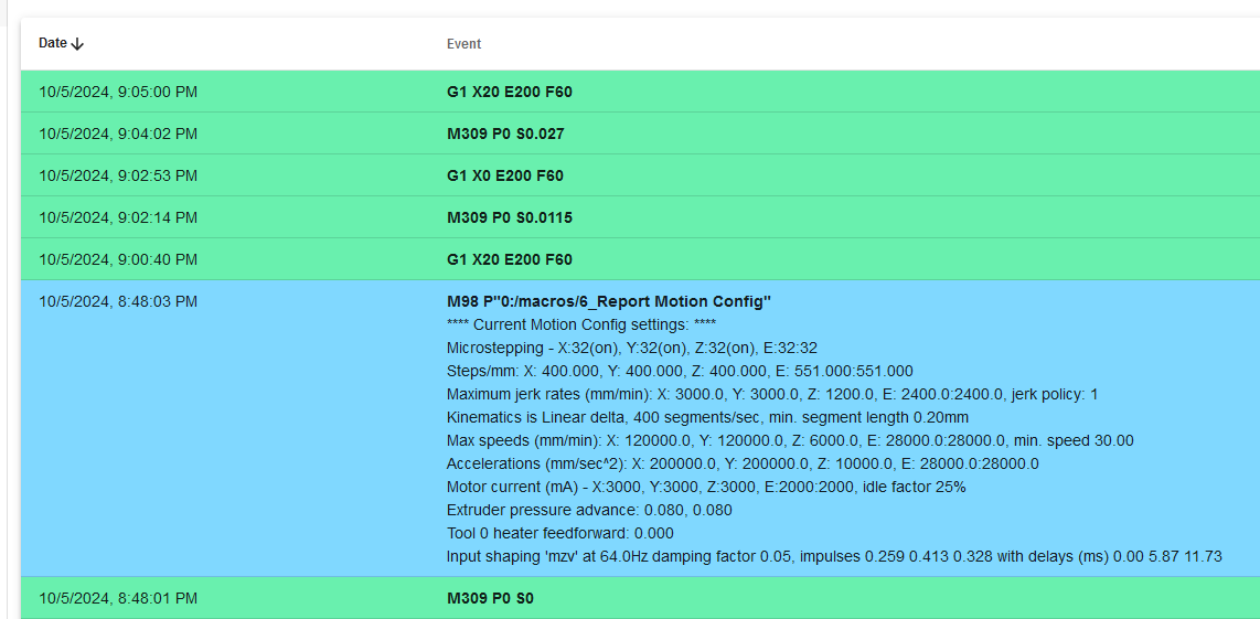
[3.6.0-beta.1] Heater feedforward not workingposted in Beta Firmware
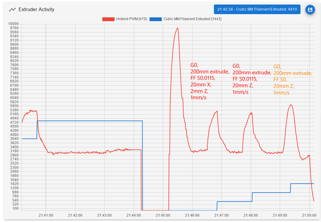
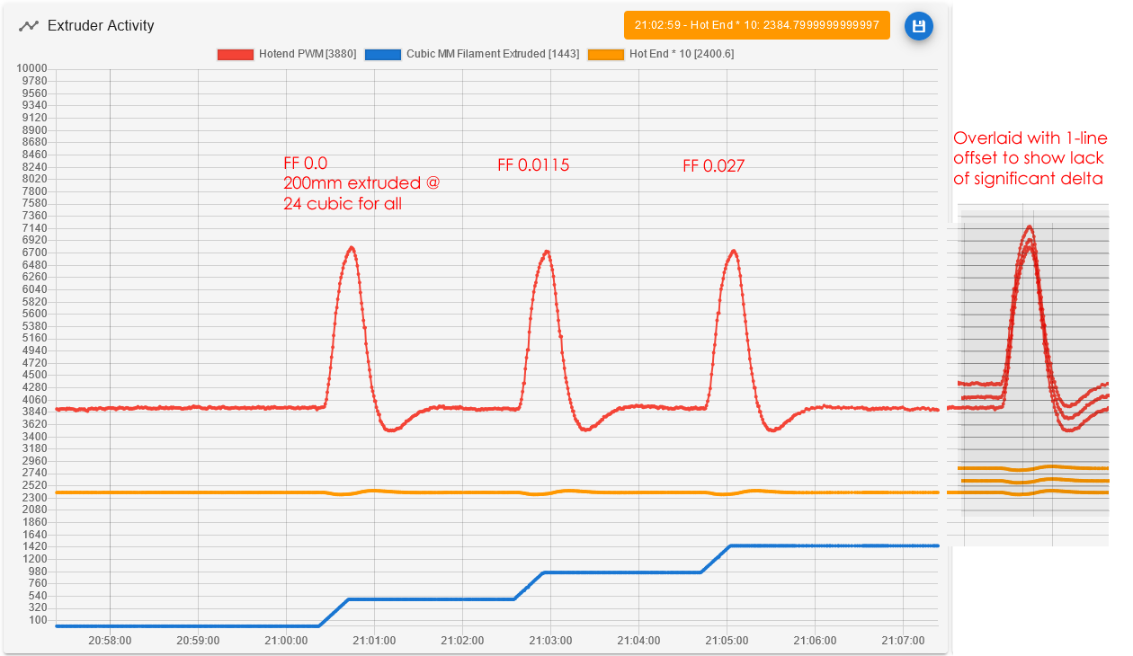
Issue: Heater feedforward appears to be broken in both the 3.6.0 5+1 alpha and the 3.6.0 beta.1, at least on my setup with E driven by a toolboard.
Platform: Linear delta, 6HC + 3HC, E is a 2WD mixing extruder on the toolboard, heater and heater temps are wired to mainboard.
Background: After getting feedforward working on 3.5.1, I started seeing extrusion dropoffs after updating to the 3.6.0 5+1 alpha. After a lot of other investigation, I traced part of the issue to M309 feedforward settings apparently having no impact on heater behavior (PWM or temps). I ran 7 meters of filament last night on the alpha with a variety of temperatures, extrusion amounts, and feedforward settings, and kept getting the same temperature outcomes (dropoff followed by overshoots). I updated to the beta this morning, and the behavior is unchanged. These results are in stark contrast to the heater behavior I observed in 3.5.1, which was nicely effective at compensating for extrusion with a value of 0.0115. See graphs and commanded gcode below.
-
RE: Software bundle 3.6.0-beta.1 now availableposted in Beta Firmware
@Notepad I have run into something similar to this, but I can't reproduce it yet... detailed my experience at the bottom of the earlier 3.6.0 alpha build thread.
-
RE: RepRapFirmware 3.6.0-alpha.4+3 available for testingposted in Beta Firmware
To follow up on the strange extrusion event, I re-ran the same print with the same config settings as before today, and extrusion appeared normal again -- so it wasn't the gcode's fault. Both prints layer shifted and were cancelled at about the same point, so out of curiosity I weighed them. The first one with the extrusion issue weighed 58% of the second one. I wondered if it would be a nice round number like half, but I guess not.