Duet3D Logo Duet3D
    • Tags
    • Documentation
    • Order
    • Register
    • Login
    1. Home
    2. lirwin17
    3. Posts
    • Profile
    • Following 0
    • Followers 0
    • Topics 0
    • Posts 27
    • Best 4
    • Controversial 0
    • Groups 0

    Posts made by lirwin17

    • RE: 1HCL Beta Test - motion judders, but only in 1 direction

      @cncmodeller

      is there any way to recor a large move so I can see if the encoder values are leading the motor judders

      This is coming in a beta soon ๐Ÿ™
      What you could do for now is a short recording whilst the motor is moving. So when the motor starts juddering, hit record in the plugin. That should record a short snippet in very high resolution.

      This might actually be preferable to a long recording in high resolution because you're going to end up with a lot of data and a huge file!

      posted in Hardware dev
      lirwin17undefined
      lirwin17
    • RE: Duet3D 1HCL - Closed Loop Controller Beta test

      @supertb1 That's worked ๐ŸŽ‰ ๐ŸŽ‰

      So from those graphs it's definitely C5, so keep it at that ๐Ÿ‘
      From your M122: tuning error: 0x1c, this is yet to be documented, but this happens when not all the required tuning moves are made. From the docs:

      manoeuvres 1, 2, 4, 8 and 16 are required

      And 0x1c means 4, 8 & 16 haven't (yet) been run - so just try to home (assuming your homing file includes running those moves - which it should if you followed the tuning page - i.e. you should have an M569.6 ... V31 in your homing file somewhere)

      Let me know if your motor then holds position after completing homing ๐ŸŽ‰

      If that works, we can move onto the x axis. Perhaps try unplugging your y motor and encoder from board 51 and plugging your x motor and encoder into board 51. I would expect your x axis to then just work (albeit it will think it's Y). If it doesn't we'll need to investigate your motor ๐Ÿ‘

      posted in Hardware dev
      lirwin17undefined
      lirwin17
    • RE: Duet3D 1HCL - Closed Loop Controller Beta test

      @supertb1 Ah this is a much better graph - is this with C20?
      Something else has caught my eye in your M122 - TMC(notifyWait,15.5%,26) - I'm pretty sure the TMC task runs at ~50% in the latest firmware, and around 15% in some older firmware. Is the firmware you're using definitely the 'unoffical' closed-loop dropbox release linked further up (https://www.dropbox.com/sh/qkexrvhgsebbz0g/AAD9gfyS8UIU5Sau311WS1oLa?dl=0)?

      I think that because the 'unoffical' build has the same version number as the latest beta, any boards that were plugged in after you updated the firmware wouldn't update automatically - since it thinks it's already on the latest beta. @dc42 might be able to confirm if it works this way.
      I assume the y-axis board is newly connected? if so, it might have fell into this trap.

      Either way, I think it would be a good idea to at least try updating again to make sure you're on the 'unoffical' dropbox build linked above.

      Just to be 100% sure, here's how I would update:

      • Download Duet3Firmware_EXP1HCL.bin from the link above
      • Drag and drop that bin file into the upload button on the system files tab
      • It should then ask if you want to install the firmware, and then go ahead and visibly install it - if it doesn't do this, this means there's a problem

      Then after that's done, maybe try running M122 again, and see if that percentage on the TMC task has jumped from 15% to >40% - that would be a good sign that this was indeed the issue, and that it's now resolved.

      If that's successful, you might want to set your C value back to 5, then please could you send another picture like that graph & we'll see if it's made any difference

      posted in Hardware dev
      lirwin17undefined
      lirwin17
    • RE: Duet3D 1HCL - Closed Loop Controller Beta test

      @supertb1

      then I ran a homing sequence which returned the G28 X warning. And again the axis fails to move the drive back to the home position before the Z axis lowers using the Home X example with the V3 maneuver. Maybe I am confused here, the encoder should tell the motor to stay where ever it is when it stopped?

      Yup you're absolutely right, the encoder should tell the motor to stay where it is even when it is stopped.
      However, what is happening here is that the drive has been (intentionally) disabled because it failed tuning.
      When you run M122 B50, you're right that it should say closed loop is enabled, but I suspect it also says something like tuning error: x where x is a non-zero value. Whenever x is non-zero, the drive is disabled because it treats it as a 'fault'. (At the moment this can be quite confusing - we're currently working on a way of making this more obvious such as a pop up in web control saying 'driver fault')
      This is also the case for

      and fails to return X and Y to home location using the homing example listed on the tuning page, however it does lower the Z axis back down at the end of the move

      In this case, the X and Y motors have been intentionally disabled because there is a tuning fault - so they will be 'limp'. The z motor however has not been disabled, so that will continue to work.

      I'll walk through the x and y axes data that you have collected separately, because I believe they have different issues.

      Y-Axis

      aba2e085-02c5-4dc4-bcc4-761797013722-image.png

      The second reason that tuning might fail is that step phase does not closely track desired step phase.
      (For the interested reader, the first reason is that step phase moves in a different direction to desired step phase - e.g. step phase decreases when desires step phase increases)
      In this case, step phase is increasing roughly 4x the speed as the desired step phase.
      At this point hopefully it becomes evident why we disable the drivers if they fail tuning - in this instance, the motor would move 4x the intended distance - probably smashing into something you don't want to smash into!

      This is normally caused by the encoder's count per step being set incorrectly (probably out by a factor of 4...)

      You gave this originally:

      Encoder Resolution 4000ppr

      I've personally found the units that the manufacturers use to be pretty confusing - this seems to be specified in PPR - pulses per revolution. However, our docs refer to CPR:

      Encoder counts per step (Cn.n) can be found from the datasheet of the encoder being used. If the value is stated as counts per revolution (CPR), divide by the steps per revolution of the stepper motor to get the count per step. For example, a 1000 CPR encoder attached to a 200 step/rev motor will have a count per step of 1000 รท 200 = 5.

      To get from PPR to CPR you divide by 4 (this is probably our factor of 4 ๐Ÿค” )
      So your 4000 PPR encoders have a CPR of 1000
      You say the motor has 200 steps, so that gives us a count per step of 1000 / 200 = 5
      This means your config.g should have C5 in your M569.1 command
      If you do, then we need to consider if the motors are actually 4000 PPR

      X-Axis

      Looking at the same graph for the x axis, the motor doesn't seem to be moving at all!
      d7af73c4-dd1a-4a57-9b14-c0ed0a409448-image.png
      I think the best thing to do is focus on getting Y working, and once it is, we can use the fact you have a working axis to find the fault in the other (perhaps a dodgy wire, motor, encoder or 1HCL board - we can start swapping things around to see what works and what breaks things)

      posted in Hardware dev
      lirwin17undefined
      lirwin17
    • RE: Duet3D 1HCL - Closed Loop Controller Beta test

      @supertb1

      Ok I double checked the wiring today, Homed the axis in closed loop and then ran a tuning maneuver

      Okie dokie, good stuff.
      Can I just confirm if the motor is working as expected in open-loop mode?
      When you say "Homed the axis in closed loop" I assume that's a typo and you homed in open-loop?
      Was that homing successful?

      You said before:

      it seams as though it cut my steps in half and is making the motor oscillate loudly

      Is this still the case? Or are you satisfied that the motor is now working correctly when attached to the duet board in open-loop mode?

      To be honest, if the motor isn't working in open-loop, then there's no chance it will work in closed-loop, so we need to get the motor working (i.e. without these 'half-steps' and loud oscillations) in open-loop first before we can move onto doing anything in closed loop (tuning moves etc...)

      On the other hand, I might have misinterpreted, and the motor is now working in open-loop? Please could you confirm either way

      posted in Hardware dev
      lirwin17undefined
      lirwin17
    • RE: Duet3D 1HCL - Closed Loop Controller Beta test

      @supertb1
      Apologies for the delayed reply, I've been moving house over the last few days so everything has been a bit hectic!

      I disconnected the motor and ran it from a separate stepper drive I have built from an Arduino and a A4988.. The motor works fine in both directions outside the system

      Okie dokie, that's good, we know the motor itself works.

      I then reconnected the motor to the drive on the 1HCL ... with the M569 p50.0 D3 [open loop] it seams as though it cut my steps in half and is making the motor oscillate loudly, but it moves

      Okay, so even in open-loop, the drive isn't behaving as expected.
      From what you have said, it almost sounds like one of the coils isn't being energised, or is only being energised intermittently - so the motor is limping along on just 1 coil.
      I don't know if @T3P3Tony has a set of standard troubleshooting instructions for when a drive doesn't work in normal open-loop mode, I'll give it a stab below, but I defer to anyone else's expertise for a more concrete procedure.

      From the fact that we know your motor works, that seems to be suggesting it is either a problem with the wiring to the motor, or a problem with the driver chip on the Duet board.
      I personally tested each one of those boards before they went out, so it's fairly certain they worked when they left me, but I suppose they could have been damage in mailing, so we should keep an open mind here.
      However, I think more likely there is an intermittent connection on at least one of your wires going to the motor.
      When you tested the motor on a separate stepper driver built from an arduino, did you use the same wiring to the motor?
      Either way, it would be worth using a multimeter to test for continuity across those wires - perhaps giving them a bit of a wiggle to test for an intermittent connection that may only show itself when the wire is in a certain position

      Let me know how you get on ๐Ÿ™‚

      posted in Hardware dev
      lirwin17undefined
      lirwin17
    • RE: Duet3D 1HCL - Closed Loop Controller Beta test

      @supertb1 hmm okay so it looks like the encoder is working...

      Perhaps that reading of 0 is correct - is the motor actually moving at all during the recording?

      If it's not, please could you check that the motor works in open loop mode - i.e. boot up the board and then run M569 P50.0 D3, and try to home the motor, move it, etc

      If it doesn't work in open loop mode, it's most likely an issue with the wiring, you could try plugging the motor into your main board and check that it works in there

      posted in Hardware dev
      lirwin17undefined
      lirwin17
    • RE: Duet3D 1HCL - Closed Loop Controller Beta test

      @maxgyver thank you for the update! Don't worry, I've not forgotten about increasing the max speed - it's actually next on my list!

      was able to increase my acceleration and jerk significantly

      Excellent that's what we like to hear ๐ŸŽ‰

      I have two motors on my Y axis. They are both wired to one 1HCL board, but only one has an encoder. It calibrates fine, and I did not spot a significant problem during printing. Only the recorded graphs were of no use on this axis (at least for me). Maybe something to keep in mind for future development

      Hmm okay ๐Ÿค” do you mean that both motors are wired into the single driver output on the 1HCL? What exactly were the issues you were having with the recorded graph?

      Furthermore, I have the impression that the drivers run in full step without any microstepping as soon as I switch to closed loop. It sounds very much like my very first printer. ๐Ÿ˜ 
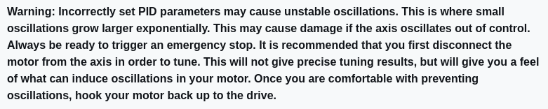
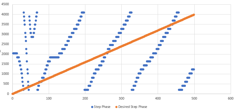
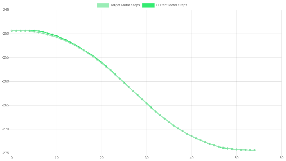
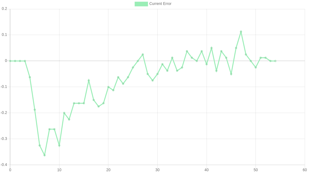
The prints also show a strong stepping pattern.

      This is an interesting one haha - so with closed loop, we kinda lose all sense of microstepping, since the motors no longer move in discrete steps, but move as close to continuously as possible. This means that in theory, the microstepping is infinite... but the keyword here is 'continuously as possible', in reality the motor has to move some discrete distance per PID iteration, and this is a function of the frequency of the PID loop (constant) and the speed of the move (variable). If you do a very slow move, I'd expect you to be getting very small discrete moves per PID cycle (the equivalent of very high mocrostepping), whereas if we're pushing the boundary on how fast we can move, you'll get very large discrete moves per PID cycle (up to a full step).
      You can actually measure the size of these discrete steps by taking a recording (with speed set to 'as fast as possible') and looking at the step phase variable, and the vertical distance between datapoints. A distance of 90 degrees means 1 step, you could work out an 'effective microstepping' from this, since you know the increments in which the motor moves.

      The good news is though, as we increase the maximum speed, the 'effective microstepping' will also increase as well, so hopefully you'll see less of the stepping pattern as we do so ๐Ÿ™‚

      posted in Hardware dev
      lirwin17undefined
      lirwin17
    • RE: Duet3D 1HCL - Closed Loop Controller Beta test

      @supertb1

      is there another report with different variables I need to run for more information?

      No, this is great ๐Ÿ‘

      I'm not sure how to read these...

      There's docs coming soon, but for now I'll talk you through it

      The first thing to say is that the raw encoder reading is 0 on both recordings - this means it doesn't seem to register the encoder as moving at all.
      This is strange because I thought that you did M122 twice after manually turning a full rotation and the encoder's reading changed... Please could you confirm this is still the case
      (See this post for more detailed information)
      95f3e05a-299f-478b-85c8-b2217e7fea0a-image.png

      posted in Hardware dev
      lirwin17undefined
      lirwin17
    • RE: Duet3D 1HCL - Closed Loop Controller Beta test

      @supertb1

      does this mean that I need to switch the positive and negative wires?

      Sorry, this error message is a bit misleading - I'll change that. The polarity should be detected automatically, so a better error message may be "encoder polarity failed to be detected"

      Please could you follow the same instructions I gave to maxgyver above (here), although on the 'movement' checkboxes down the right hand side, please could you check 'polarity detection'

      We should then be able to take a look at the graph and see what's going on ๐Ÿ™‚

      posted in Hardware dev
      lirwin17undefined
      lirwin17
    • RE: Duet3D 1HCL - Closed Loop Controller Beta test

      @supertb1 @t3p3tony

      Edit: I got my .5 and .6s confused ๐Ÿคฆ I've corrected them now

      Yes, Tony is also right here:

      I think you are using M569.5 instead of M569.6
      What does sending
      M569.6 P50.0 V31
      Result in?

      The M569.5 command is for recording. This does let you pass in a manoeuvre (V parameter) to do. So running M569.5 as you describe would technically work to do a tuning move...
      However, you'll also be making a recording each time, so you'll quickly fill up your SD card with recordings. For this reason, unless you intend to do a recording, using M569.6 is preferable to do a tuning move.

      For anyone curious as to why there are 2 GCODE commands to do tuning moves, the rationale is that with HTTP delays etc, it is unlikely that you'd be able to send M569.5 and M569.6 quickly enough to record a tuning move. For that reason, M569.5 allows you to specify a tuning move that gets started just before the recording is started.

      posted in Hardware dev
      lirwin17undefined
      lirwin17
    • RE: Duet3D 1HCL - Closed Loop Controller Beta test

      @supertb1

      it dawned on me that I probably would have to disconnect the encoder from the 1HCL board as well... you guys did a great job on these boards... very smart...lol

      Hmm you should never need to disconnect the encoder from the board unless you want to - the board should work in open-loop mode without anything needing to be disconnected, and you shouldn't need to disconnect it to cycle power or anything.

      That yes to the closed loop enable was there before I updated the 1HCL board to the latest firmware and now at power up it reports "no" to the close loop enable

      Righty I'm just looking over your config.g, it's been posted a few times, so let me just re-post here so that we're all looking at the same thing:

      G4 S3 ;wait for expansion boards to start
      M569.1 P50.0 S1 T2 C20 E20 R100 I0 D0 ; Configure the 1HCL board at CAN address 50 with a quadrature encoder on the motor shaft that has 20 steps per motor full step.
      M569.1 P51.0 S1 T2 C20 E20 R100 I0 D0 ; Configure the 1HCL board at CAN address 51 with a quadrature encoder on the motor shaft that has 20 steps per motor full step.
      M569 P50.0 D4 S1 ; Configure the motor on the 1HCL at can address 50 as being in closed-loop drive mode (D4), Open loop (D2) and not reversed (S1) X axis
      M569 P51.0 D2 S1 ; Configure the motor on the 1HCL at can address 51 as being in closed-loop drive mode (D4), Open loop (D2) and not reversed (S1) Y axis
      M569 P0.0 S1 ; physical drive 0.0 goes forwards Z 1-2 axis
      M569 P0.4 S1 ; physical drive 0.4 goes forwards Extruder
      M584 X50.0 Y51.0 Z0.0:0.1 E0.4 ; set drive mapping
      M671 X-122.25:689.20 Y0:0 S3.0 ; leadscrews at left (connected to Z0) and right (connected to Z1) of X axis
      M350 X32 Y32 Z32 E16 I1 ; configure microstepping with interpolation
      M92 X106.5 Y257 Z795.00 E339.00 ; set steps per mm
      M566 X900.00 Y900.00 Z60.00 E120.00 ; set maximum instantaneous speed changes (mm/min)
      M203 X6000.00 Y6000.00 Z180.00 E1200.00 ; set maximum speeds (mm/min)
      M201 X500.00 Y500.00 Z20.00 E250.00 ; set accelerations (mm/s^2)
      M906 X1000 Y3000 Z3000 E800 I30 ; set motor currents (mA) and motor idle factor in per cent
      M84 S30 ; Set idle timeout
      M917 X0 Y0 ; Set the closed loop axes to have a holding current of zero
      

      The first thing that jumps out is line 5:

      M569 P51.0 D2 S1 ; Configure the motor on the 1HCL at can address 51 as being in closed-loop drive mode (D4), Open loop (D2) and not reversed (S1) Y axis
      

      Your comment says it's closed loop, but the actual command is using D2, which is an open loop mode.
      However, your line above using P50.0 is correct, and that seems to be the driver you have been using, so I assume you are aware of this and this is all fine.

      It might be worth only having one closed loop board plugged in at a time whilst we're diagnosing this issue. Just to rule out issues like them accidentally sharing a CAN address or something like that.

      I suspect the problem here is line 2:

      M569.1 P50.0 S1 T2 C20 E20 R100 I0 D0
      

      This might be our fault - that particular command has gone through a number of changes, and it should have been updated in all the docs - except we seem to have missed this section! So if you've copy-pasted from that, this may be where our issues are coming from - I'll update that page now.
      The GCODE dictionary page for M569.1 is definitely correct though, so I'll re-write your M569.1 command from first principles:

      • Your motor driver is 50.0 - so P50.0
      • Your encoder is a quadrature on motor shaft - so T2
      • From googling your motor serial number, you have this motor? That page gives a 'resolution' of 1000. No units though, how helpful. I'll assume that's CPR. That motor is also 200 step/rev, so we do 1000 รท 200 = 5 - so C5
      • Sensible error thresholds are maybe 5 & 10 - so E5:10
      • We'll leave R,I,D as default so you don't need to include them for now

      Putting that all together:

      M569.1 P50.0 T2 C5 E5:10
      

      I suspect when your config.g file was running, it was erroring at your M569.1 command - so never getting to M569 to turn the 'no' to 'yes' in M122.

      It might be worth running M98 P"config.g" manually and seeing if any errors come back. Then, change your M569.1 command for my M569.1 command, run M98 P"config.g" and hopefully no errors will come back.
      Once that's done, turn it off and on again, and you should be good to go ๐Ÿ‘

      posted in Hardware dev
      lirwin17undefined
      lirwin17
    • RE: Duet3D 1HCL - Closed Loop Controller Beta test

      @supertb1
      Hmm there are are a few M122 outputs so I've lost track a little...

      The first ones show Closed loop enabled: yes, but then some later ones show no.

      The problem seems to be that when you come to run the tuning move, that yes has flipped to a no...

      Please could you run through the following:

      • power up (so config.g runs)
      • run a manoeuvre command - it might be best to start with the simplest one V1

      And at each point check M122 to see when yes flipps to no. Is it showing yes after config.g has run, or is it only when the move is run that it flips to no?

      posted in Hardware dev
      lirwin17undefined
      lirwin17
    • RE: Duet3D 1HCL - Closed Loop Controller Beta test

      Hi @supertb1,

      Sorry, I'm not 100% clear on the actual issue here. Thanks for providing your M122 output, from tuning error: 0x1f, it seems like no runtime tuning has happened. Similar to when an axis is un-homed, a driver that is untuned will not move, so if the issue is that the axis isn't moving then that would be the expected behaviour in this instance.
      However, if you have run tuning, there is a deeper issue here.

      Details of tuning can be found on this page. Specifically, the two 'what do I need to do?' sections (1, 2) are compulsory before the system will move (eventually these should be part of the online config tool, but not just yet for the beta test)

      If you weren't aware of this page in the docs, that's really useful for us to know because it tells us we need to draw more attention to that page ๐Ÿ™‚

      Thanks!
      Louis

      posted in Hardware dev
      lirwin17undefined
      lirwin17
    • RE: Duet3D 1HCL - Closed Loop Controller Beta test

      @maxgyver

      I've gone down a bit of a rabbit hole looking at why it can't run at top speeds - but I think I finally have an answer!

      Forgive me, but I might talk about RPM here instead of mm/min. It just makes it a bit less printer-dependant.
      For reference, RPM = (mm/min) * (step/mm) * (rev/step), and here are some common conversion that we've talked about (for an average printer):

      22000 mm/min = 550 RPM
      36000 mm/min = 900 RPM

      In theory, the maximum speed is given by the PID loop frequency. Each iteration of the PID loop can command the motor to take 1 step (=rotate 0.005 degs). The PID loop currently runs at 12000 Hz.
      This means that the theoretical max speed is 12000 x 0.005 x 60=3600 RPM.

      Why then are we topping out at ~900 RPM (measured on my Ender 3, other's results may be different)
      The answer is how long it takes to communicate the new motor currents to the driver ICs that we use.
      At the minute, this takes ~0.064ms. At low RPMs, this is negligible. But at high RPMs, it means the motor has moved on a significant amount between deciding what current to set, and actually setting that current. At my max speed of 900RPM, it's moved on a whole 0.2 steps. We should be able to fix this by looking at the current RPM and 'predicting' how much the motor will have moved by the time the currents have been sent.

      Thanks for pointing this out! It would be useful if I could gauge just how much of an issue this is. Would the current top speed be an issue for you? Or is it just a nice-to-have? If anyone else would have issues with this limitation, please do say ๐Ÿ™‚
      This feedback will then impact our decision on what to focus on improving next ๐ŸŽ‰

      posted in Hardware dev
      lirwin17undefined
      lirwin17
    • RE: Duet3D 1HCL - Closed Loop Controller Beta test

      @alankilian

      Aye I'm not 100% sure of the terminology ๐Ÿ˜†

      But I've experimentally verified that this motor gives 1000 of these
      0dea7198-9b74-4be4-987c-f783f503d590-image.png
      full cycles per revolution, and therefore 4000 rising/falling edges per full revolution ๐Ÿ‘

      In order to be consistent with stepperonline and some other datasheets that I've seen, we've documented 'CPR' as the number of complete cycles per revolution - which is at odds with your understanding of the terminology. This is what this period of testing is for though! So thanks for raising it! If a lot of people are getting confused, we'll look at changing the terminology that we're using to be in line with what you say. But for now, even if it's technically wrong, we'll keep the terminology as CPR so at least we're consistent with the common motor datasheets ๐Ÿ˜›

      I'll start a new thread on an idea that I think can get you both the expected great open-loop performance of a stepper and the error-recovery of a closed-loop system

      I look forward to reading it!

      posted in Hardware dev
      lirwin17undefined
      lirwin17
    • RE: Duet3D 1HCL - Closed Loop Controller Beta test

      @alankilian

      That's an impressive graph.

      Cheers!

      you are showing a measurement resolution of around 0.02 steps which means you have a 10,000 counts-per-revolution encoder

      The fact I'm plotting error might make it appear like I have more resolution than I do...
      As an example, imagine the motor isn't moving so I'm getting a constant encoder reading. But my target is increasing at a rate of 0.000001/s. You'd get an error reading of 0, 0.000001, 0.00002 etc... which might imply I have a (very good) resolution of 0.000001. Whereas the actual encoder reading hasn't changed so we can't tell anything about the encoder resolution. I think something along those lines is going on here ๐Ÿค”

      The actual encoder I'm using is a ~ยฃ30 encoder/motor combo from stepper online. Which gives an impressive 1000 CPR. The cheapest you can get is actually only ~ยฃ17 for 1000 CPR - which includes both the motor and the high-res encoder ๐Ÿคฏ! I was pretty surprised with how cheap you could get high-res encoders like these.
      You're completely right though that we need to consider how we can get the high-res required without breaking the bank, so something else that's in the works is using a hall effect 'encoder' like the AS5047D - which gives an impressive 2048 'CPR'. To be honest I have found them fairly noisy compared to the quadratures, but even that noise hasn't lead to any noticeable quality defects on my Ender 3 when compared to open loop control ๐ŸŽ‰

      One final trick up my sleeve is to dissect the CPR signal into it's individual pulses. Given that a single 'count' is actually made up of 4 pulses, we get an extra factor of 4 resolution for free!
      Now technically I don't think there are any guarantees that these pulses are evenly spaced, but even if they are unevenly spaced, it still gives us an increase in resolution. (With counts, we could be up to 0.999... out, whereas even with unevenly spaced pulses, we could only ever be up to 0.4999 out (If that makes sense ๐Ÿค” ))

      So dissecting the signal gives me effectively a 4000 CPR encoder for the low low price of ~ยฃ30 ๐ŸŽ‰

      posted in Hardware dev
      lirwin17undefined
      lirwin17
    • RE: Duet3D 1HCL - Closed Loop Controller Beta test

      @maxgyver

      I just installed the latest firmware. The D an I parameter plots are now much more comparable to the one's in the manual, and changes in the parameters can now be seen in the plot

      Ah excellent! Sorry about that. At least the new firmware is working & out there now.

      BTW, I often get some parameters as this zigzag lines...

      Hmm yeah... I'll look into this. It looks like sometimes it's just reading back 0 when it should't be. I'm confident this is a issue with the data transmission between the board & DWC though - the closed loop system itself should still be performing well ๐Ÿ™ I'll get back to you on this ๐Ÿ™‚

      I noticed that when I put the motor in closed loop mode the maximum achievable speed is reduced to about 22000mm/s. In open loop mode I run at 36000mm/s easily.

      I'll definitely look into this - we don't want to be reducing our top speed with closed loop!

      posted in Hardware dev
      lirwin17undefined
      lirwin17
    • RE: Duet3D 1HCL - Closed Loop Controller Beta test

      @alankilian

      HERE'S an article I wrote (oh, god, 21 years ago) about how to tune a PID system.

      Looks like a great article! Thanks for linking it. I might add it to a 'further resources' section on the tuning docs ๐Ÿ™‚

      It looks like you've got EXCELLENT logging and plotting ability, so you should be able to tune fairly well.

      Thankyou ๐Ÿ™‡

      As I've said in the past, I'm not sure what people think they are going to get out of closed-loop steppers that they don't get from open-loop steppers other than recovery if you crash your head and miss a bunch of steps.

      You're definitely right there - but recovery like that can be a big advantage if you're dealing with especially large/costly prints. I used to do some work on a 1m^3 build volume printer that could easily churn through ยฃ1000 of filament on a single print. Because the extrusions it laid down were so big, if one was unlucky enough to slightly bend upwards into the path of the head, it could easily cause skipped steps and trash a very expensive print. IMHO Closed loop definitely makes sense as a sort of 'insurance' system in these cases - pay a little more upfront for closed loop motors to avoid the risk of trashing a ยฃ1000 print.

      But closed loop does also have some other advantages:

      • Less power usage, so motors run cooler. Generally when a motor is at a constant speed in closed loop mode (especially when that speed is 0) it will not be running at full current. This is especially pronounced on z-axis motors where 99% of the time the motors can be practically off, and yet they will still hold position if nudged. As opposed to an open loop system running a holding current through them all the time
      • You can get higher speeds whilst maintaining accuracy! Hopefully something I might work on in my spare time is seeing just how fast a closed loop drive can run whilst still maintaining accuracy. Watch this space... Having closed loop on all your drives means you can finally answer the question "Just how fast can I run whilst maintaining an accuracy of < x steps"

      It is not going to get you better accuracy than open-loop if you are not crashing. In fact, I'd be willing to bet that accuracy goes way down to about 2 or 3 steps even when well tuned. (I'm ready and willing to be proven wrong, this is based on decades of tuning DC servos closed-loop with a lot of different mechanical systems.)

      I defer to your decades of experience here, although on my Ender 3 this is the kind of movement profile I get back from a simple 5mm (~25 step) move:

      5bc174eb-9a2c-4b8e-9f8b-83d7cfbedea6-image.png

      And plotting the error alone:

      ddc4cf8e-25fb-489c-9476-f37b1e8af655-image.png

      In the roughly 'steady state' section of the move the error very rarely exceeded 0.1 steps (both graph's y axes are in units of steps - my old high school teachers would be yelling at me to label that ๐Ÿ˜œ)
      As you would expect the most error comes in the initial transient part as the acceleration increases - we're hopefully looking to eliminate that in the near future with a feed-forward mechanism, that feeds forward the next move into the control algorithm.

      Although as we've already said, the target audience for these probably isn't ender 3's so maybe I've made a moot point! Either way I'm really interested to see how it performs on larger axes, and whether your prediction holds true, or if we can maintain this level of performance!

      posted in Hardware dev
      lirwin17undefined
      lirwin17
    • RE: Duet3D 1HCL - Closed Loop Controller Beta test

      Hi @maxgyver ,

      The Step Phase and desired step phase plot is still all over the place.

      This graph looks good ๐Ÿ‘
      Step phase basically means the current rotational position of the motor (step phase = current step position * 90 mod 360). As the motor rotates 4 steps, I would expect to see the graph you give - it increases by 360 degrees, but rolls over once due to that mod 360.
      The main point about step phase is that it roughly follows desired step phase - which it does ๐ŸŽ‰

      But I get stuck at the derivative value that does not really influence the graph.

      Hmm okay, each setup will have different requirements for the D parameters - especially if an axis is particularly heavy. It might just be that you need to increase the D parameter to see an impact - but you're definitely right to start small to reduce the risk of causing unstable oscillations.
      If you're worried that the D parameter is having no effect at all, you should be able to toggle on the recording of the PID control variables, so you'll be able to see the actual D value that's being calculated, and the effect it's having on the overall PID control signal. If you find that it is too small, you can increase the D value.
      But do heed the warning on the tuning page:
      94d1f7ef-7c9f-4309-966e-e474a22d7683-image.png

      We've already had some issues with the latest beta firmware being out of date - which I won't rule out causing these issues. As promised, we've just published an 'unofficial' firmware at this dropbox link.
      Feel free to install this updated firmware and see if it has any effect - but don't forget to undo the multiplication by 4 that we did on your CPR! This updated firmware works as-per the docs, so requires a CPR value for the C parameter ๐Ÿ™‚

      posted in Hardware dev
      lirwin17undefined
      lirwin17